Mitsubishi Electric Jet Towel JT-MC106G-W-NA Installation Manual
Hand dryer
Hide thumbs
Also See for Jet Towel JT-MC106G-W-NA:
- Instruction manual (12 pages) ,
- Handbook (28 pages)
Table of Contents
Advertisement
Available languages
Available languages
Quick Links
Download this manual
See also:
Instruction Manual
MODEL
JT-MC106G-W-NA
Unit color
-W
White
INSTALLATION MANUAL
Read the manual thoroughly before beginning installation to ensure the unit is installed safely and correctly.
Installation shall comply with local requirements and Electrical Code and be performed by the dealer or a qualifi ed
professional in accordance to local jurisdiction.
The "INSTRUCTION MANUAL" is for the customer. Be sure to hand it to the customer.
INDEX
How to open/close the front cover
Hand dryer
6 - 11
Location of Name plate indicating
Model name and Electrical ratings
Input Power: 120 Vac Single-phase
For Dealers and Installers
2
3
3
3
4
5
5
5
5
12
13
13
13
14
15
NA 1
875HJ9901
Indoor use only
Advertisement
Chapters
Table of Contents

Related Manuals for Mitsubishi Electric Jet Towel JT-MC106G-W-NA


Summary of Contents for Mitsubishi Electric Jet Towel JT-MC106G-W-NA
-
Page 1: Table Of Contents
875HJ9901 Hand dryer MODEL JT-MC106G-W-NA Location of Name plate indicating Model name and Electrical ratings Unit color White Input Power: 120 Vac Single-phase Indoor use only For Dealers and Installers INSTALLATION MANUAL Read the manual thoroughly before beginning installation to ensure the unit is installed safely and correctly. -
Page 2: Safety Precautions
Safety Precautions The dangers arising from improper handling and the extents of the dangers are classified and explained as shown below. The following may lead to death or serious Warning personal injury if handled incorrectly. Do not install in locations where they Wiring work shall be done by a may be leakages of combustible gas. -
Page 3: Pre-Installation Checks
Pre-installation checks Warning Input Power: 120 Vac Single-phase is used. Using the incorrect power supply may cause fi res, electric shocks or malfunctions. Checking the installation environment Do not install the unit in the following types of locations. (This may cause malfunctions.) Outdoors Locations where the temperature could be lower than 32 F (0 C). -
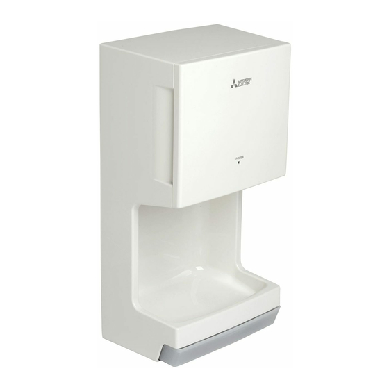
Page 4: Names Of Parts And External Dimensions
Names of parts and external dimensions Main unit " (250) " " Installation panel (170) " Air fi lter (52) " Power (100) light " (163) Drain tank Unit (in. (mm)) NOTE Confi rm the details in the "Installation conditions" (Page 5). Front Inside the front cover Power light... -
Page 5: Installation Conditions
Installation conditions Required space for installation Rear side Top side Unit (in. (mm)) Be sure to secure at least the Caution distances listed in the right- Isolation Location hand table from walls, fl ammable distance Main (combustible) materials and so unit Above "... -
Page 6: Installation Method
Installation method For confi rmation Input Power: 120 Vac Single-phase power is being used (using the incorrect power supply may cause fi res, electric shocks or malfunctions). The ground fault circuit interrupter is attached (not attaching a ground fault circuit interrupter may result in electric shocks). - Page 7 Installation method - continuation Fix the installation panel onto the wall with 5 accessory mounting screws Installation panel (5 30). The "Installation position guide" illustrated on the right is recommended. When installing on a wall, select a wall with a fl...
- Page 8 Installation method - continuation 1. Remove the drain tank. Drain tank 2. Open the front cover and remove the Air fi lter Air fi lter air fi lter. Refer to "How to open/close the front cover" (Page 13). Main unit Open panel Pull the tab and open the front...
- Page 9 Installation method - continuation Caution Warning Make sure that the main unit Input Power: 120 Vac Single-phase is used. does not fall as the base is not attached to the wall with screws. Using the incorrect power supply may cause fi res, electric shocks Injuries may be caused if the unit or malfunctions.
- Page 10 Installation method - continuation 1. Place the power cable through the cord bushing and reattach it to the circuit case with the terminal block cover mounting screw. Terminal block cover mounting screw 2. Check that the power cable and wires Terminal are not pinched anywhere.
- Page 11 Installation method - continuation 1. Open the front cover and attach the air fi lter. Air fi lter 2. Close the front cover and push the tab into latch the front cover shut. Main unit panel 3. Check that the front cover is securely closed. Check to see that the front cover is fitted Caution securely.
-
Page 12: Test Run
Test Run Step What to check for Check Is the proper power being used? Check the power supply (JT-MC106G-W-NA type: Input Power: 120 Vac Single-phase voltage Incorrect power supply may cause malfunctions or low wind power. Turn the ground fault circuit interrupter on. -
Page 13: Initial Setting Checks
Initial setting checks How to open/close the front cover How to open the front cover Pull the tab for opening the Hold the handle are on the Open. front cover. right hand side of the main unit. Main unit Main unit Handle Pull... -
Page 14: Turning The Heater On
Initial setting checks - Continuation Turning the heater on Open the front cover. Open Front cover Press the heater switch or the maintenance switch and let the settings light turn on. Turn the heater switch "ON". Heater switch The heater may not operate during continued use as there is the danger of scalding when the temperature of the warm air rises. -
Page 15: Turning The Sensor Off Before Maintenance
Initial setting checks - Continuation Turning the sensor off before maintenance Pull the tab and open the front cover. Main unit Pull Front cover Front cover Open the front cover. Sensor light Sensor switch Open Press the sensor switch and let the setting light turn on. - Page 16 Tokyo Building 2-7-3, Marunouchi, Chiyoda-ku, Tokyo 100-8310, Japan NA 16...
- Page 17 Séchoir à mains MODÈLE JT-MC106G-W-NA Emplacement de la plaque signalétique indiquant le nom du modèle et les caractéristiques électriques Couleur de l'appareil -W blanc Puissance d'entrée : 120 VCA à phase unique Pour utilisation à l'intérieur seulement Pour les revendeurs et les installateurs MANUEL D'INSTALLATION Veuillez lire entièrement ce manuel avant de commencer l'installation afi...
-
Page 18: Mesures De Sécurité
Mesures de sécurité Les dangers provenant d'une mauvaise manipulation et la portée des dangers sont classifiés et expliqués comme montrés ci-dessous. Ce qui suit pourrait causer des blessures graves, Avertissement voire mortelles, si l'appareil est manipulé de manière inadéquate. N'installez pas l'appareil à des endroits où... -
Page 19: Vérifi Cations Avant L'installation
Vérifi cations avant l'installation Avertissement Puissance d'entrée : 120 VCA à phase unique utilisés. L'utilisation d'une alimentation électrique non appropriée peut provoquer des incendies, des décharges électriques ou des anomalies de fonctionnement. Vérifi er l'environnement d'installation N'installez pas l'appareil dans les emplacements suivants. (Cela pourrait entraîner un mauvais fonctionnement de l'appareil.) Extérieur Les endroits où... -
Page 20: Nom Des Pièces Et Dimensions Externes
Nom des pièces et dimensions externes Appareil principal " (250) " " Panneau d'installation (170) " Filtre à air (52) " Voyant de (100) l'alimentation " (163) Réservoir de vidange Unité (po. (mm)) REMARQUE Confi rmez les détails dans la section « Conditions de l'installation » (page 5). Avant Voyant de À... -
Page 21: Conditions D'installation
Conditions d'installation Espace d'installation requis Côté arrière Côté supérieur Unité (po. (mm)) Veillez respecter au moins les Attention distances répertoriées dans la Distance Emplacement table de droite par rapport aux d'isolation Appareil murs, matériaux infl ammables principal Au-dessus 5 " (150) Côté... -
Page 22: Méthode D'installation
Méthode d'installation Pour confi rmation Puissance d'entrée: 120 VCA à phase unique sont utilisés (l'utilisation de la mauvaise tension d'alimentation peut provoquer des incendies, des décharges électriques ou des mauvais fonctionnements). Le disjoncteur de fuite à la terre est raccordé (ne pas raccorder un disjoncteur de fuite à la terre peut provoquer des décharges électriques). - Page 23 Méthode d'installation - suite Fixez le panneau d'installation sur le mur avec les 5 vis de montage Panneau d'installation 30). Le « Guide de position d'installation » illustré sur la droite est recommandé. Lors de l'installation sur un mur, choisissez un mur avec une surface à...
- Page 24 Méthode d'installation - suite 1. Retirez le réservoir de vidange. Réservoir de vidange 2. Ouvrez le couvercle avant et retirez le Onglet Filtre à air Filtre à air fi ltre à air. Voir « Comment ouvrir / fermer le couvercle avant »...
- Page 25 Méthode d'installation - suite Attention Avertissement Assurez-vous que l'appareil ne Puissance d'entrée : 120 VCA à phase unique utilisés. tombe pas lorsque la base n'est pas fi xée au mur avec des vis. L'utilisation d'une alimentation électrique non appropriée peut La chute de l'appareil peut provoquer des incendies, des décharges électriques ou des provoquer des blessures.
- Page 26 Méthode d'installation - suite 1. Faites passer le câble d'alimentation par le passe-câble et fi xez-le de nouveau au boîtier de la carte de circuit imprimé avec la vis de Vis de montage montage du couvercle du bornier. du couvercle du bornier Couvercle du bornier...
- Page 27 Méthode d'installation - suite 1. Ouvrez le couvercle avant et fi xez le fi ltre à air. Filtre à air 2. Fermez le couvercle avant et poussez l'onglet dans le loquet pour bien fermer le couvercle Panneau de l'appareil avant. 3.
-
Page 28: Essai De Fonctionnement
Essai de fonctionnement Étape Vérification à effectuer Vérifier Utilisez-vous la bonne tension d'alimentation ? (JT-MC106G-W-NA type : Puissance d'entrée : 120 VCA à Vérifi ez la tension de phase unique l'alimentation Une tension d'alimentation incorrecte peut provoquer de mauvais fonctionnements ou une faible force d'air de séchage. -
Page 29: Vérifi Cations Initiales De La Confi Guration
Vérifi cations initiales de la confi guration Comment ouvrir / fermer le couvercle avant Comment ouvrir le couvercle avant Tirez l'onglet pour ouvrir le Maintenez la poignée qui Ouvrez. couvercle avant. est sur le côté droit de l'appareil. Onglet Appareil principal Appareil principal... -
Page 30: Mettre En Marche Le Chauffe Air
Vérifi cations initiales de la confi guration - Suite Mettre en marche le chauffe air Ouvrez le couvercle avant. Ouvert Couvercle avant Appuyez sur le commutateur du chauffe air ou sur le commutateur de l'entretien et laissez s'allumer le voyant des paramètres. Commutateur du chauffe air Mettez le commutateur du chauffe air à... -
Page 31: Désactivation Du Capteur Avant Tout Entretien
Vérifi cations initiales de la confi guration - Suite Désactivation du capteur avant tout entretien Tirez l'onglet et ouvrez le couvercle avant. Onglet Appareil principal Tirer Couvercle avant Couvercle avant Ouvrez le couvercle avant. Voyant du capteur Commutateur du capteur Ouvert Appuyez sur le commutateur du capteur et laissez allumer son voyant. - Page 32 Tokyo Building 2-7-3, Marunouchi, Chiyoda-ku, Tokyo 100-8310, Japan CF 16...