Intel D845GBV Product Manual
Desktop boards
Hide thumbs
Also See for D845GBV:
- Product supplement document (36 pages) ,
- Specification update (18 pages) ,
- Product supplement specification update (15 pages)
Table of Contents
Advertisement
Advertisement
Table of Contents

Subscribe to Our Youtube Channel
Related Manuals for Intel D845GBV


Summary of Contents for Intel D845GBV
- Page 1 Intel Desktop Boards ® D845GRG and D845GBV Product Guide A84615-001 Order Number:...
-
Page 2: Revision History
Contact your local Intel sales office or your distributor to obtain the latest specifications and before placing your product order. Copies of documents which have an ordering number and are referenced in this document, or other Intel literature, may be obtained from Intel Corporation by going to the World Wide Web site at: http://www.intel.com/ or by calling 1-800-548-4725. -
Page 3: Table Of Contents
Contents 1 Desktop Board Features Components... 9 Processor ...11 Main Memory ...12 ® Intel 845G Chipset...12 ® Intel 82845G Graphics Memory Controller Hub (GMCH) ...13 ® Intel 82801DB I/O Controller Hub (ICH4)...13 Firmware Hub (FWH) ...13 Input/Output (I/O) Controller...13 Graphics Subsystem ...14 Audio Subsystem ...14... - Page 4 Intel Desktop Boards D845GRG and D845GBV Product Guide 2 Installing and Replacing Desktop Board Components Before You Begin ...21 Installing the I/O Shield ...22 Installing and Removing the Desktop Board...23 Installing and Removing a Processor ...24 Installing a Processor ...24 Installing the Processor Fan Heat Sink ...24...
- Page 5 Place Battery Marking ...80 Use Only for Intended Applications...80 Figures 1. Desktop Board D845GRG Components ... 9 2. Desktop Board D845GBV Components ...10 3. Location of Standby Power Indicator...18 4. Installing the I/O Shield ...22 5. Desktop Board D845GBV Mounting Holes...23 6.
- Page 6 12. Removing the Battery ...35 13. Back Panel Connectors ...64 14. Audio Connectors ...65 15. Power and Hardware Control Connectors...66 16. Desktop Board D845GBV Add-in Card and Peripheral Interface Connectors ...67 17. Front Panel Headers...68 Tables 1. Feature Summary ... 7 2.
-
Page 7: Desktop Board Features
DIMMs based on 512 Mbit technology up to 2 GB, but this technology has not been validated on these Intel desktop boards. For more information about the latest list of tested memory, refer to the Intel World Wide Web site at: http://support.intel.com/support/motherboards/desktop/... - Page 8 • Voltage sensing to detect out of range values ✏ NOTE ® For information about Intel updates, and device drivers, go to the Intel World Wide Web site at: http://support.intel.com/support/motherboards/desktop/ ® 82562ET 10/100 Mbit/sec Platform LAN Connect (PLC) device and RJ-45 connector —...
-
Page 9: Components
Auxiliary line-in connector (ATAPI) Rear chassis fan connector (tachometer input) CD-ROM connector (ATAPI) Back panel connectors 12 V processor core voltage connector Intel 82845G (GMCH) Processor socket Processor fan connector (tachometer input) DIMM sockets Super I/O controller Main power connector... -
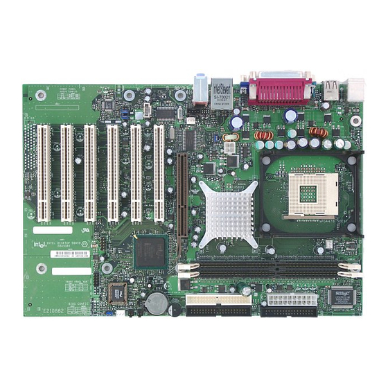
Page 10: Desktop Board D845Gbv Components
Intel Desktop Boards D845GRG and D845GBV Product Guide Figure 2 shows the location of the major components on Desktop Board D845GBV. Audio codec Front panel audio header Auxiliary line-in connector (ATAPI) Rear chassis fan connector (tachometer input) CD-ROM connector (ATAPI) -
Page 11: Processor
Desktop Boards D845GRG and D845GBV require an ATX12V compliant power supply to function according to desktop board specifications. Both boards have two ATX12V compliant power supply connectors that are needed to provide extra power to the Intel 845G chipset and Intel Pentium 4 processor or Intel Celeron processor. -
Page 12: Main Memory
Desktop Boards D845GRG and D845GBV have been designed to support DIMMs based on 512 Mbit technology up to 2 GB, but this technology has not been validated on these Intel desktop boards. For more information about the latest list of tested memory, refer to the Intel World Wide Web site at: http://support.intel.com/support/motherboards/desktop/... -
Page 13: Intel ® 82845G Graphics Memory Controller Hub (Gmch)
82845G Graphics Memory Controller Hub (GMCH) The GMCH provides the processor, system memory, AGP, and hub interfaces in the Intel 845 chipset platform. Features on Desktop Boards D845GRG and D845GBV include: • Single processor support with 533 MHz or 400 MHz data transfer rates •... -
Page 14: Graphics Subsystem
Supports RJ-45 connector with status indicator LEDs • Programmable transit threshold • Configurable EEPROM that contains the MAC address LAN Subsystem Software For LAN software and drivers, refer to the D845GRG or D845GBV link on Intel’s World Wide Web site at: http://support.intel.com/support/motherboards/desktop... -
Page 15: Rj-45 Lan Connector Leds
USB device. These Intel desktop boards support up to six USB 2.0 ports via ICH4; four ports routed to the back panel and two routed to a USB front panel header. USB 2.0 ports are backward compatible with USB 1.1 devices. -
Page 16: Expansion Slots
✏ NOTE Desktop Boards D845GRG and D845GBV are only compatible with 1.5 V AGP cards. AGP is a high-performance interface for graphics-intensive applications, such as 3D graphics. AGP is independent of the PCI bus and is intended for exclusive use with graphical display devices. -
Page 17: Ide Auto Configuration
ACPI ACPI gives the operating system direct control over the power management and Plug & Play functions of a computer. The use of ACPI with Desktop Board D845GRG or D845GBV requires an operating system that provides full ACPI support. Desktop Board Features... -
Page 18: Suspend To Ram (Instantly Available Pc Technology)
The Intel desktop board’s standby power indicator, shown in Figure 3, is lit when there is standby power to the system. This includes the memory modules and PCI bus connectors, even when the computer appears to be off. -
Page 19: Hardware Management
• PME# wakeup support Power Connectors Desktop Boards D845GRG and D845GBV have two power connectors. See Figure 15 on page 66 for the location of the power connectors. Fan Connectors Desktop Boards D845GRG and D845GBV have two chassis fan connectors and one processor fan connector. -
Page 20: Wake From Ps/2 Keyboard/Mouse
Power-On Self-Test (POST). Battery A battery on the Intel desktop board keeps the values in CMOS RAM and the clock current when the computer is turned off. See Chapter 2 starting on page 21 for instructions on how to replace the battery. -
Page 21: Installing And Replacing Desktop Board Components
2 Installing and Replacing Desktop Board Components This chapter tells you how to: • Install the I/O shield • Install and remove the desktop board • Install and remove a processor • Install and remove memory • Install and remove an AGP card •... -
Page 22: Installing The I/O Shield
Intel Desktop Boards D845GRG and D845GBV Product Guide Installing the I/O Shield The Intel desktop board comes with an I/O shield. When installed in the chassis, the shield blocks radio frequency transmissions, protects internal components from dust and foreign objects, and promotes correct airflow within the chassis. -
Page 23: Installing And Removing The Desktop Board
(#2 bit) screwdriver. Refer to Appendix B for regulatory requirements and installation instructions and precautions. Figure 5 shows the location of the eight mounting holes for Desktop Board D845GBV. Desktop Board D845GRG has six mounting holes. Figure 5. Desktop Board D845GBV Mounting Holes... -
Page 24: Installing And Removing A Processor
Desktop Boards D845GRG and D845GBV have an integrated processor fan heat sink retention mechanism (RM). For instructions on how to install the processor fan heat sink to the integrated processor fan heat sink RM, refer to the boxed processor manual or the Intel World Wide Web site http://support.intel.com/support/processors/pentium4/intnotes478.htm Figure 6. -
Page 25: Connecting The Processor Fan Heat Sink Cable
Figure 7. Connecting the Processor Fan Heat Sink Cable to the Processor Fan Connector Removing the Processor For instruction on how to remove the processor fan heat sink and processor, refer to the processor installation manual or the Intel World Wide Web site at: http://support.intel.com/support/processors/pentium4/intnotes478.htm Installing and Replacing Desktop Board Components... -
Page 26: Installing And Removing Memory
You can access the PC Serial Presence Detect Specification at: http://www.intel.com/technology/memory/pcsdram/spec/ Desktop Boards D845GRG2 and D845GBV have two 184-pin DIMM sockets arranged as banks 0 and 1, as shown in Figure 8. If installing a single DIMM, install it in bank 0. -
Page 27: Removing Dimms
10. Replace the computer’s cover and reconnect the AC power cord. Installing and Removing an AGP Card The AGP connector supports 1.5 V 4X and 2X AGP cards. Intel desktop boards have an integrated AGP card retention mechanism (RM). Installing an AGP Card Follow these instructions to install an AGP card: 1. -
Page 28: Removing The Agp Card
Intel Desktop Boards D845GRG and D845GBV Product Guide Removing the AGP Card Follow these instructions to remove the AGP card from the RM: 1. Remove the screw (B) that secures the card’s metal bracket (A) to the chassis back panel. -
Page 29: Connecting The Ide Cable
ATA hard drive as a slave to an ATAPI CD-ROM drive. For correct function of the cable: • Attach the cable end with the single connector to the Intel desktop board. • Attach the cable end with the two closely spaced connectors to the drives. -
Page 30: Connecting The Front Panel Header
Always turn off the power and unplug the power cord from the computer before changing the jumper. Moving the jumper with the power on may result in unreliable computer operation. The location of the Intel desktop board’s BIOS configuration jumper is shown in Figure 11. J9H2 Figure 11. -
Page 31: Installing A Front Panel Audio Solution
Installing a Front Panel Audio Solution To install the cable that connects the front panel audio solution to the front panel audio header, follow these steps: 1. Observe the precautions in “Before You Begin” on page 21. 2. Turn off all peripheral devices connected to the computer. Turn off the computer and disconnect the AC power cord. -
Page 32: Clearing Passwords
Intel Desktop Boards D845GRG and D845GBV Product Guide Clearing Passwords This procedure assumes that the board is installed in the computer and the configuration jumper block is set to normal mode. 1. Observe the precautions in “Before You Begin” on page 21. -
Page 33: Replacing The Battery
Installing and Replacing Desktop Board Components Replacing the Battery A coin-cell battery (CR2032) powers the real-time clock and CMOS memory. When the computer is not plugged into a wall socket, the battery has an estimated life of three years. When the computer is plugged in, the standby current from the power supply extends the life of the battery. - Page 34 Intel Desktop Boards D845GRG and D845GBV Product Guide VORSICHT Bei falschem Einsetzen einer neuen Batterie besteht Explosionsgefahr. Die Batterie darf nur durch denselben oder einen entsprechenden, vom Hersteller empfohlenen Batterietyp ersetzt werden. Entsorgen Sie verbrauchte Batterien den Anweisungen des Herstellers entsprechend.
-
Page 35: Removing The Battery
To replace the battery, follow these steps: 1. Observe the precautions in “Before You Begin” (see page 21). 2. Turn off all peripheral devices connected to the computer. Disconnect the computer’s power cord from the AC power source (wall outlet or power adapter). 3. - Page 36 Intel Desktop Boards D845GRG and D845GBV Product Guide...
-
Page 37: Updating The Bios
Updating the BIOS with the Intel Utility With the Intel Express BIOS Update utility you can update the system BIOS while in the Windows environment. The BIOS file is included in an automated update utility which combines the functionality of the Intel Flash Memory Update Utility and the ease-of use of Windows-based installation wizards. -
Page 38: Updating The Bios With The Intel ® Flash Memory Update Utility
Updating the BIOS with the Intel Utility With the Intel Flash Memory Update Utility you can update the system BIOS from a floppy disk or other bootable media. The utility available from the Web provides a simple method for creating a bootable flash memory update floppy that will automatically update your BIOS. -
Page 39: Recovering The Bios
Recovering the BIOS It is unlikely that anything will interrupt the BIOS update; however, if an interruption occurs, the BIOS could be damaged. The following steps explain how to recover the BIOS if an update fails. The following procedure uses recovery mode for the Setup program. See page 30 for more information on Setup modes. - Page 40 Intel Desktop Boards D845GRG and D845GBV Product Guide...
-
Page 41: Using The Bios Setup Program
Allocates and Boot Integrity resources for Service (BIS)* hardware credentials, and components configures extended configuration memory settings * For information about the BIS, refer to the Intel Web site at: http://developer.intel.com/design/security/index1.htm Advanced Security Power Advanced Security Power Configures Sets Configures... -
Page 42: Maintenance Menu
No options Signature CPU Microcode No options Update Revision * For information about the BIS, refer to the Intel Web site at: http://developer.intel.com/design/security/index1.htm Description Selects a different menu screen Moves cursor up or down Moves cursor to the next field... -
Page 43: Main Menu
Main Menu Maintenance Main Table 8 describes the Main Menu. This menu reports processor and memory information and is used to configure the system date and system time. Table 8. Main Menu Feature Options BIOS Version No options Processor Type No options Processor Speed No options... -
Page 44: Advanced Menu
Intel Desktop Boards D845GRG and D845GBV Product Guide Advanced Menu Maintenance Main Table 9 describes the Advanced Menu. This menu is used to set advanced features that are available through the chipset. Table 9. Advanced Menu Feature Options PCI Configuration... -
Page 45: Pci Configuration Submenu
• PCI Slot 6 IRQ Priority • Auto (default) (Note) • 3 • 5 • 9 • 10 • 11 Note: PCI slots 4, 5, and 6 are available only on Desktop Board D845GBV. Advanced Security Power PCI Configuration Boot Configuration Peripheral Configuration IDE Configuration... -
Page 46: Boot Configuration Submenu
Intel Desktop Boards D845GRG and D845GBV Product Guide Boot Configuration Submenu Maintenance Main The submenu shown in Table 11 is used to set the Plug & Play options and the power-on state of the Numlock key. Table 11. Boot Configuration Submenu... -
Page 47: Peripheral Configuration Submenu
Peripheral Configuration Submenu Maintenance Main This submenu shown in Table 12 is used for configuring computer peripherals. Table 12. Peripheral Configuration Submenu Feature Options • Disabled Serial Port A • Enabled • Auto (default) • 3F8 (default) Base I/O Address (This feature is present •... - Page 48 Intel Desktop Boards D845GRG and D845GBV Product Guide Table 12. Peripheral Configuration Submenu (continued) Feature Options • 378 (default) Base I/O Address (This feature is present • 278 only when Parallel Port is set to Enabled) • IRQ 5 Interrupt (This feature is present •...
-
Page 49: Ide Configuration Submenu
IDE Configuration Submenu Maintenance Main This submenu shown in Table 13 is used to configure IDE device options. Table 13. IDE Configuration Submenu Feature Options • Disabled IDE Controller • Primary • Secondary • Both (default) • Disabled IDE Bus Master •... -
Page 50: Primary/Secondary Ide Master/Slave Submenus
Intel Desktop Boards D845GRG and D845GBV Product Guide Primary/Secondary IDE Master/Slave Submenus Maintenance Main There are four IDE submenus: Primary master, primary slave, secondary master, and secondary slave. Table 14 shows the format of these IDE submenus. For brevity, only one example is shown. -
Page 51: Diskette Configuration Submenu
Diskette Configuration Submenu Maintenance Main This submenu shown in Table 15 is used to configure the floppy drive. Table 15. Diskette Configuration Submenu Feature Options • Disabled Floppy Controller • Enabled (default) • Disabled Floppy A • 360 KB 5¼” •... -
Page 52: Event Log Configuration Submenu
Intel Desktop Boards D845GRG and D845GBV Product Guide Event Log Configuration Submenu Maintenance Main The submenu shown in Table 16 is used to configure the event logging features. Table 16. Event Log Configuration Submenu Feature Options Event Log No options... -
Page 53: Video Configuration Submenu
Video Configuration Submenu Maintenance Main The submenu shown in Table 17 is used to configure video features. Table 17. Video Configuration Submenu Feature Options • 4MB Graphics Aperture Size • 8MB • 16MB • 32MB • 64MB (default) • 128MB •... -
Page 54: Usb Configuration Submenu
Intel Desktop Boards D845GRG and D845GBV Product Guide USB Configuration Submenu Maintenance Main The menu shown in Table 18 is used to configure USB features. Table 18. USB Configuration Submenu Feature High Speed USB Legacy USB Support Advanced Security Power... -
Page 55: Chipset Configuration Submenu
Chipset Configuration Submenu Maintenance Main The menu shown in Table 19 is used to configure advanced chipset features. Table 19. Chipset Configuration Submenu Feature Options • Extended Configuration • • Auto (default) SDRAM Frequency • 200 MHz • 266 MHz •... -
Page 56: Security Menu
Intel Desktop Boards D845GRG and D845GBV Product Guide Security Menu Maintenance Main The menu shown in Table 20 is used to set passwords and security features. Table 20. Security Menu If no password entered previously: Feature Supervisor Password Is User Password Is... -
Page 57: Power Menu
Power Menu Maintenance Main The menu shown in Table 21 is used to set power management features. Table 21. Power Menu Feature Options ACPI No Options • Stay Off After Power Failure • Last State (default) • Power On • Stay Off (default) Wake on PCI PME •... -
Page 58: Boot Menu
Intel Desktop Boards D845GRG and D845GBV Product Guide Boot Menu Maintenance Main The menu shown in Table 23 is used to set the boot features and the boot sequence. Table 23. Boot Menu Feature Options • Disabled Silent Boot • Enabled (default) •... -
Page 59: Boot Device Priority Submenu
Boot Device Priority Submenu Maintenance Main The submenu represented in Table 24 is for setting boot devices priority. Table 24. Boot Device Priority Submenu Options Feature • Removable Device Boot Device • Hard Drive Boot Device • ATAPI CD-ROM Boot Device •... -
Page 60: Removable Devices Submenu
Intel Desktop Boards D845GRG and D845GBV Product Guide Removable Devices Submenu Maintenance Main The submenu in shown Table 26 is for setting removable devices. Table 26. Removable Devices Submenu Feature Options Removable Device Dependent on installed (Note) removable devices Note: This boot device submenu appears only if at least one boot device of this type is installed. This list will display up to four removable devices, the maximum number of removable devices supported by the BIOS. -
Page 61: Exit Menu
Exit Menu Maintenance Main The menu shown in Table 28 is used to exit the BIOS Setup program, saving changes, and loading and saving defaults. Table 28. Exit Menu Feature Description Exit Saving Changes Exits and saves the changes in CMOS SRAM. Exit Discarding Changes Exits without saving any changes made in the BIOS Setup program. - Page 62 Intel Desktop Boards D845GRG and D845GBV Product Guide...
-
Page 63: Technical Reference
5 Technical Reference Board Connectors Intel desktop board connectors can be divided into three groups: • Back panel connectors • Midboard connectors — Audio connectors — Power and hardware connectors — Add-in board and peripheral interface connectors • Front panel headers... -
Page 64: Back Panel Connectors
Intel Desktop Boards D845GRG and D845GBV Product Guide Back Panel Connectors Figure 13 shows the back panel connectors. Item ✏ NOTE The line out connector, located on the back panel, is designed to power either headphones or amplified speakers only. Poor audio quality may occur if passive (non-amplified) speakers are connected to this output. -
Page 65: Midboard Connectors
Midboard Connectors Audio Connectors Figure 14 shows the location of the audio connectors. Item Table 29 shows the pin assignments for the front panel audio header. Table 29. Front Panel Audio Header Signal Names (J8A1) Signal Name AUD-MIC AUD-MIC-BIAS AUD-FPOUT-R HP-ON AUD-FPOUT-L Description... -
Page 66: Power And Hardware Connectors
Desktop Boards D845GRG and D845GBV require an ATX12V compliant power supply to function according to desktop board specifications. Both boards have two ATX12V compliant power supply connectors that are needed to provide extra power to the Intel 845G chipset and Pentium 4 processor. -
Page 67: Add-In Card And Peripheral Interface Connectors
Add-In Card and Peripheral Interface Connectors Figure 16 shows the add-in card and peripheral interface connectors for Desktop Board D845GBV. Desktop Board D845GRG has three PCI slots. Item Description CNR (optional) PCI bus connector 6 PCI bus connector 5 PCI bus connector 4... -
Page 68: Front Panel Headers
Intel Desktop Boards D845GRG and D845GBV Product Guide Front Panel Headers Figure 17 shows the location of the front panel headers. Item Description Front panel audio (see Table 29 on page 65 for pin assignments) Front panel USB Front panel Alternate power/sleep LED Table 30 shows the pin assignments for the front panel USB 2.0 header. -
Page 69: Front Panel Header (J9G1)
Table 31 shows the pin assignments for the front panel header. Table 31. Front Panel Header (J9G1) Pin Signal In/Out Description Hard Drive Activity LED HD_PWR Hard disk LED pull- up (330 Ω) to +5 V HDA# Hard disk active LED Reset Switch Ground Ground... -
Page 70: Desktop Board Resources
Intel Desktop Boards D845GRG and D845GBV Product Guide Desktop Board Resources Memory Map Table 32. System Memory Map Address Range (decimal) Address Range (hex) 1024 K - 2097152 K 100000 - 7FFFFFF 960 K - 1024 K F0000 - FFFFF... -
Page 71: Interrupts
Interrupts Table 34. Interrupts System Resource I/O channel check Reserved, interval timer Reserved, keyboard buffer full Reserved, cascade interrupt from slave PIC COM2* COM1* LPT2 (Plug and Play option) / ** Floppy drive controller LPT1* Real time clock Onboard mouse port (if present, else user available) Reserved, math coprocessor Primary IDE (if present, else user available) Secondary IDE (if present, else user available) - Page 72 Intel Desktop Boards D845GRG and D845GBV Product Guide...
-
Page 73: A Error Messages And Indicators
A Error Messages and Indicators Desktop Boards D845GRG and D845GBV report POST errors in two ways: • By sounding a beep code • By displaying an error message on the monitor BIOS Beep Codes The BIOS beep codes are listed in Table 35. The BIOS also issues a beep code (one long tone followed by two short tones) during POST if the video configuration fails (a faulty video card or no card installed) or if an external ROM module does not properly checksum to zero. -
Page 74: Bios Error Messages
Intel Desktop Boards D845GRG and D845GBV Product Guide BIOS Error Messages When a recoverable error occurs during the POST, the BIOS displays an error message describing the problem. Table 36. BIOS Error Messages Error Message GA20 Error Pri Master HDD Error... - Page 75 Table 36. BIOS Error Messages (continued) Error Message Memory Size Decreased Memory Size Increased Memory Size Changed No Boot Device Available Off Board Parity Error On Board Parity Error Parity Error NVRAM / CMOS / PASSWORD cleared by Jumper <CTRL_N> Pressed Error Messages and Indicators Explanation Memory size has decreased since the last boot.
- Page 76 Intel Desktop Boards D845GRG and D845GBV Product Guide...
-
Page 77: B Regulatory Compliance
Instructions and precautions for integrators who are installing the desktop board in a chassis. Safety Regulations Desktop Boards D845GRG and D845GBV comply with the safety regulations stated in Table 37 when correctly installed in a compatible host system. Table 37. -
Page 78: Product Certification Markings
Desktop Boards D845GRG and D845GBV have the following product certification markings: • UL joint US/Canada Recognized Component mark: consists of small c followed by a stylized backward UR and followed by a small US. Includes adjacent UL file number for Intel desktop boards: E210882 (component side). •... -
Page 79: Installation Precautions
Installation Precautions When you install and test the desktop board, observe all warnings and cautions in the installation instructions. To avoid injury, be careful of: • Sharp pins on connectors • Sharp pins on printed circuit assemblies • Rough edges and sharp corners on the chassis •... -
Page 80: Chassis And Component Certifications
Use Only for Intended Applications All Intel desktop processor boards are evaluated as Information Technology Equipment (I.T.E.) for use in personal computers for installation in homes, offices, schools, computer rooms, and similar locations. The suitability of this product for other applications or environments, such as medical,...
Need help?
Do you have a question about the D845GBV and is the answer not in the manual?
Questions and answers