
Related Manuals for GE Café CS980SN1SS


Summary of Contents for GE Café CS980SN1SS
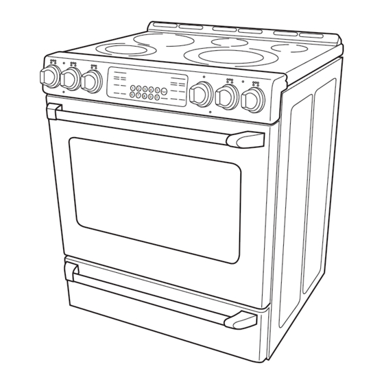
- Page 1 GE Consumer & Industrial Technical Service Guide February 2009 GE Café™ Radiant Range CS980SN1SS 31-9182 GE Appliances General Electric Company Louisville, Kentucky 40225...
- Page 2 If grounding wires, screws, straps, clips, nuts, or washers used to complete a path to ground are removed for service, they must be returned to their original position and properly fastened. GE Consumer & Industrial Technical Service Guide Copyright © 2009 All rights reserved.
-
Page 3: Table Of Contents
Table of Contents Component Locator Views ............................10 Control Features ................................7 Control Panel ..................................13 Convection Fan Assembly ............................18 Cooling Blower .................................18 Diagnostics and Service Information ........................23 Door Lock Assembly ...............................21 Electronic Range Control (ERC) ..........................13 Electronic Range Control (ERC) Pin Locator ......................20 ERC Failure Codes ................................23 Griddle Operation ................................17 Ground Strap Installation for 3-Wire Power Cord ................... -
Page 4: Introduction
Introduction *The new GE Café™ Radiant Ranges have the following features: • Extra Large Capacity (5.0 cu. ft.) Self-Clean Convection Oven. • PreciseAir™ Convection System ― Features an innovative fan that reverses direction for optimal air and heat circulation, providing even cooking and precise baking and roasting results. -
Page 5: Nomenclature
Nomenclature C S 9 8 0 S N 1 S S C = GE Café™ SS = Stainless Steel S = Slide-In Engineering Code Feature Pack Model Year Model - Stainless Serial Number The fi rst two numbers of the serial number identify the month and year of manufacture. -
Page 6: Ground Strap Installation For 3-Wire Power Cord
4. Remove the lower center screw (if present) and Ground Strap Installation for 3-Wire Power loosen the upper center screw on the terminal Cord block. Remove the two 1/4-in. hex-head screws and 5. Slide the open slotted end of the ground strap the wire cover from the back of the range. -
Page 7: Control Features
Control Features Using the upper oven controls. Using the upper oven controls. (Throughout this manual, features and appearance may vary from your model) Features and appearance may vary. Oven Control, Clock, Timer and Features BAKE Pad OVEN LIGHT Pad Touch to select the bake function. Touch to turn the oven light on or off. - Page 8 Adjust the upper oven thermostat. Adjust the upper oven thermostat. Note: This adjustment will not affect the broiling or the self-cleaning temperatures. The adjustment will be retained in memory after a power failure. The oven temperature can be adjusted up as much as To Adjust the Thermostat 35°F or down as much as 35°F.
- Page 9 Using the griddle. Using the griddle. The non-stick coated griddle provides an extra-large To turn on the surface units for the entire griddle, turn the cooking surface for meats, pancakes or other food knob clockwise. usually prepared in a frying pan or skillet. To turn on the surface unit for the back half of the Note: The griddle will discolor over time as it becomes griddle, turn the knob counterclockwise.
-
Page 10: Component Locator Views
Component Locator Views Front View (Shown with Oven Door Removed) Control Panel Broil Element Meat Probe Outlet Oven Temperature Sensor Convection Fan Bake Element Lower Oven Drawer Lower Oven Compartment (Shown with Lower Oven Drawer Removed) Thermostat Capillary Tube Broil Element Bake Element Roller Catch (Continued next page) - Page 11 Rear View (Shown with Back Cover, Terminal Cover and Griddle Relay Cover Removed) Cooling Fan Broil Element Convection Element Convection Fan Motor Range Lockout Relay Griddle Relay #1 Griddle Relay #2 Bake Element Rangetop (Shown with Rangetop wire harnesses and ground wire disconnected.) Hot Surface Indicator Light Assembly Dual Surface Element Dual Surface Element...
-
Page 12: Lower Oven Drawer
Range Components WARNING: Sharp edges may be exposed when servicing. Use caution to avoid injury. Wear Kevlar gloves or equivalent protection. Note: When in the closed position, the strike on the Lower Oven Drawer back of the drawer is captured by the roller catch. The strike is riveted in place and is not adjustable. -
Page 13: Electronic Range Control (Erc)
6. Remove the two 1/4-in. hex-head screws and 3. Remove the 2 Phillips-head locator pins from the the heat shield from the range. top of the range. 4. Place a towel or protective item across the top of each side panel. 5. -
Page 14: Lower Oven Bottom Element
4. Carefully lift the 2 tabs out from the panel fold, 4. Reach behind the element and pull off the 2 then remove the ERC from the control panel. element wire connectors. 5. Remove the two 1/4-in. hex-head screws that attach the element to the oven fl... -
Page 15: Lower Oven Control
4. Reach behind the element and pull off the 2 6. Squeeze and remove the capillary bulb clips and element wire connectors. remove them from the holes in the oven ceiling. 5. Remove the six 1/4-in. hex-head screws that attach the top element to the oven ceiling. Holes in Ceiling 7. -
Page 16: Lower Oven Operation
Lower Oven Operation Note: The lower oven cannot be used during a self-clean cycle of the upper oven. The lower oven operates in the following manner: When the lower oven control is turned counterclockwise, • The control contacts COM to NO close supplying L1 to the baking elements, pilot lamp and heating lamp. •... -
Page 17: Griddle Operation
Range Lockout Relay The range lockout feature (on some models), allows The relay is also energized when the oven door is the user to lockout the surface units, upper oven, locked (COM to NO closed). When energized, the and control panel so they cannot be activated. lockout relay will open contacts 7 to 1 and 9 to 3, When the control is set for RANGE LOCKOUT, the disconnecting L2 from the surface units. -
Page 18: Cooling Blower
Cooling Blower Convection Fan Assembly The two-speed cooling blower is located on the rear The convection fan assembly is located on the of the range. Air is pulled in by the blower blades back wall of the oven cavity and consists of the through slots below the control panel and circulated convection cover, fan blade, and motor. -
Page 19: Thermal Switch
Heat Maintained Convection Roast preheats with bake element and broil element operating (cycling) alternately. Heat maintained with bake element and broil element operating (cycling) alternately. Fan rotates CCW. Preheat and Heat Maintained Red Box indicates cycling contacts Convection Bake - Multi Rack preheats with bake element and broil element operating (cycling) Red Box indicates cycling contacts alternately. -
Page 20: Electronic Range Control (Erc) Pin Locator
Electronic Range Control (ERC) Pin Locator TB640 TB630 TB102 TB650 TB655 TB620 TB101 RY 500A1 RY 540B RY 502A1 RY 501A1 TB660 TB661 CN950 CN2 - Sensor, Thermal Switch, Door Lock, TB101 - L1 Switch, Door Unlock Switch, Probe Switch, Door Unlock Switch, Probe TB102 - Neutral CN950 - Glass Touch Board TB620 - Oven Light... -
Page 21: Door Lock Assembly
• CAM – The cam on the motor performs two Door Lock Assembly functions: The door lock assembly consists of a lock motor Positions the lock hook in the door to prevent cam and switch assembly (switches #1, #2, #3, and opening during clean operation. - Page 22 Lock Assembly Removal The lock assembly is attached to the front of the range by two T-15 Torx screws. To replace the door lock it is necessary to place the control panel in the service position (See .), remove the lock assembly Control Panel insulation, and two 1/4-in.
-
Page 23: Diagnostics And Service Information
Diagnostics and Service Information ERC Failure Codes The oven may stop operating but not give an F code on the display immediately. F codes are stored in non volatile eeprom memory until 2 of the same fault occur consecutively. After that, it will be displayed. They can be recalled by pressing together: TIMER, CLOCK, 9. -
Page 24: Schematic
Schematic WARNING: Disconnect electrical power before servicing. Caution: Label all wires prior to disconnection. Wiring errors can cause improper and dangerous operation. Verify operation after servicing. Schematic Diagram – 24 –... -
Page 25: Warranty
This warranty is extended to the original purchaser and any succeeding owner for products purchased for home use within the USA. If the product is located in an area where service by a GE Authorized Servicer is not available, you may be responsible for a trip charge or you may be required to bring the product to an Authorized GE Service location for service.