Advertisement
NOTE:
Please read all instructions
carefully before using this
product
Table of Contents
Safety Notice
Hardware Identifier
Assembly Instruction
Parts List
Warranty
Ordering Parts
Model
WM-354
Retain This
Manual for
Reference
05-27-03
OWNER'S
MANUAL
COMPETITOR BENCH
IMPEX FITNESS PRODUCTS
14777 DON JULIAN RD., CITY OF INDUSTRY, CA 91746
Tel: (800) 999-8899 Fax: (626) 961-9966
www.impex-fitness.com
info@impex-fitness.com
WM-354
Advertisement

Related Manuals for Impex COMPETITOR WM-354


Summary of Contents for Impex COMPETITOR WM-354
- Page 1 Assembly Instruction Parts List Warranty Ordering Parts Model WM-354 Retain This Manual for Reference 05-27-03 OWNER'S MANUAL COMPETITOR BENCH WM-354 IMPEX FITNESS PRODUCTS 14777 DON JULIAN RD., CITY OF INDUSTRY, CA 91746 Tel: (800) 999-8899 Fax: (626) 961-9966 www.impex-fitness.com info@impex-fitness.com...
-
Page 2: Table Of Contents
PARTS LIST...……. WARRANTY...…. ORDERING PARTS...… BEFORE YOU BEGIN Thank you for selecting the COMPETITOR WM-354 Bench by IMPEX FITNESS PRODUCTS. carefully before using the machine. to provide you complete customer satisfaction. If you have any questions, or find there are missing or damaged parts, we guarantee you complete satisfaction through direct assistance from our factory. -
Page 3: Important Safety Notices
BEFORE BEGINNING ANY EXERCISE PROGRAM, CONSULT YOUR PHYSICIAN. THIS IS ESPECIALLY IMPORTANT FOR INDIVIDUALS OVER THE AGE OF 35 OR PERSONS WITH PRE-EXISTING HEALTH PROBLEMS. INSTRUCTIONS BEFORE USING ANY FITNESS EQUIPMENT. IMPEX INC. ASSUMES RESPONSIBILITY SUSTAINED BY OR THROUGH THE USE OF THIS PRODUCT. -
Page 4: Hardware Identifier
HARDWARE IDENTIFIER... -
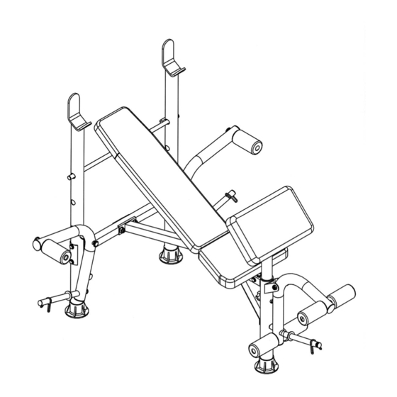
Page 5: Assembly Instructions
ASSEMBLY INSTRUCTION Tools Required Assembling the Machine: Two Adjustable Wrenches NOTE: It is strongly recommended two or more people assembling this machine to avoid possible injury. STEP 1 (See Diagram 1) A.) Plug the two Stabilizer End Caps (#24) onto the bottom of the two Rear Upright Beams (#1). - Page 6 STEP 2 (See Diagram 2) A.) Plug a Stabilizer End Cap (#24) onto the bottom of Front Leg (#8). Attach the Front Leg to the Main Seat Support (#6). Secure it with three M8 x 5/8” Hex Bolts (#33) and Ø...
- Page 7 STEP 3 (See Diagram 3) A.) Attach one 3/4” Washer (#31) onto a M10 x 6” Hex Bolt (#35). Insert the Bolt through the Butterfly (#9). Secure the Bolt with one M10 x 5/8” Regular Nut (#36) B.) Insert the Bolt through the Rear Upright Beam (#1). Secure it with a Ø ¾” Washer (#31) and M10 Aircraft Nut (#32).
- Page 8 STEP 4 (See Diagram 4) A.) Attach the hole-side of the Backrest Supports (#14) onto both ends of the pivot on the Main Seat Support (#6). Place the other end rest against the Backrest Adjustment Bar (#4). B.) Place the Backrest Board (#15) onto the Backrest Supports. Secure it with four M6 x 1 3/8”...
- Page 9 STEP 5 (See Diagram 5) A.) Attach the Arm Curl Pad (#17) to the Arm Curl Stand (#13). Secure it with two M8 x 5/8” Hex Bolts (#33) and Ø 5/8” Washers (#28). B.) Insert the Arm Curl Stand into the top opening on the Front Leg. Secure it with a Lock Knob (#25).
-
Page 11: Parts List
PARTS LIST KEY NO. DESCRIPTION Rear Upright Beam Cross Brace Curved Bracket Backrest Adjustment Bar Flat Bracket Main Seat Support Diagonal Support Front Leg Butterfly Butterfly Foam Tube Leg Developer Foam Tube Arm Curl Stand Backrest Support Backrest Board Seat Pad Arm Curl Pad Round Sleeve 1”... -
Page 12: Warranty
IMPEX authorized service center or for products used for commercial or rental purposes. No other warranty beyond that specifically set forth above is authorized by IMPEX.