Table of Contents
Advertisement
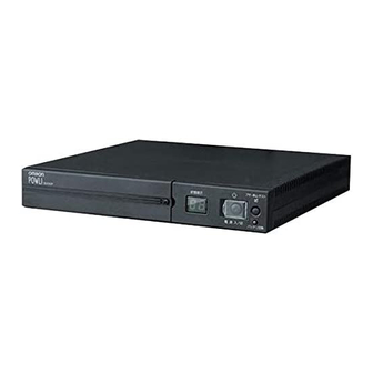
Uninterruptible Power Supply (UPS)
Instruction Manual
• This manual gives you important information to use the this unit safely and therefore be sure to
read it before installation and use.
• Keep this manual handy at the place where you install the this unit so that you can read it
whenever necessary.
BX35F/BX50F/BX50FW/BX75SW
Advertisement
Table of Contents

Related Manuals for Omron POWLI BX35F


Summary of Contents for Omron POWLI BX35F
- Page 1 Uninterruptible Power Supply (UPS) BX35F/BX50F/BX50FW/BX75SW Instruction Manual • This manual gives you important information to use the this unit safely and therefore be sure to read it before installation and use. • Keep this manual handy at the place where you install the this unit so that you can read it...
- Page 2 ● The UPS protects (backs up) personal computers, displays, peripherals, and so on up to a power consumption of 350VA/210W (BX35F), 500VA/300W (BX50F, BX50FW), 750 VA/450W (BX75SW) from failures in the power supply, such as power failures and voltage variations.
-
Page 3: Introduction
IMPORTANT SAFETY INSTRUCTION 1.SAVE THESE INSTRUCTIONS. This manual contains important instruction for Model BX35F, BX50F, BX50FW, BX75SW. That should be followed during instruction of the UPS and batteries. 2.SYMBOL This symbol indicates earth ground. This symbol indicates turning on UPS. - Page 4 Procedure from installation to operation Read “Safety precautions” Start Pages 4 – 10 Remove the product from the package and check the contents Page 11 Installation/connection Perform installation and connection Page 15 Check the operation Page 23 Preparation for operation Charge the battery Page 25 Measure the backup time...
-
Page 5: Table Of Contents
Explanation of symbol used on unit ....................14 2. Installation and connection ........................15 Precautions and notes on installation and connection ..............15 Installation and connection(BX35F/BX50F/BX50FW) ..............18 Installation and connection (BX75SW) ..................... 20 Checking the operation ........................23 3. Preparation for operation ........................... 25 Charging the battery ......................... -
Page 6: Safety Precautions
● Dropping or toppling the unit may cause injury. ● The weight of this unit is approximately: 5 kg (BX35F/BX50F/BX50FW)/ 9 kg (BX75SW). ● If you drop the unit, stop using it and have an inspection and repair be done. - Page 7 ● Overcurrent may damage the UPS. Connect the unit to a wall outlet (commercial power) with a current capacity of 8A or more (BX35F) or 12A or more (BX50F, BX50FW, and BX75SW). ● Otherwise, the power cord may be heated.
- Page 8 Safety precautions Caution (for installation and connection) Do not pinch or tie the cable of the unit. ● Doing so may cause the cable to be damaged or heated, which may cause an electric shock or a fire. ● If the cable is damaged, stop using the unit and the cable must be repaired. For repair, contact us;...
- Page 9 Use a specified battery for replacement. ● Not doing so may cause a fire. ● Product model: BXB50F (battery pack for BX35F/BX50F/BX50FW) BXB75S (battery pack for BX75SW) Do not replace the battery in a place where there is flammable gas.
- Page 10 Safety precautions Caution (for battery replacement) Do not short the battery with metal objects. ● Doing so could cause an electric shock, fire or burn. ● Some electrical energy still remains inside the spent battery. Do not put the battery into fire or do not break it. ●...
- Page 11 Safety precautions Notes Before stopping the commercial power to the unit, turn OFF the power switch of the unit. ● The unit enters Battery Mode when commercial power is stopped. If you frequently use the unit in Battery Mode, the battery life may be significantly shortened. Do not connect a page printer (laser printer, etc.) to the unit.
- Page 12 Safety precautions Explanation Usual operation ● You may either leave the power switch of the unit on (operation status) or turn it off each time when stopping the connected system. You can choose either of the operation methods for your convenience. We recom- mend turning off the power switch when you do not use connected devices for a long time.
-
Page 13: Preparation
1-1 Checking the contents Check whether all the package contents are included and there is no damage found on their appearance. If you should notice defects or anything wrong, contact us; ____ (1) Accessories related to the main unit BX35F BX50F BX50FW BX75SW User’s manual... -
Page 14: Part Names
1. Preparation 1-2 Part names BX35F/BX50F Digital Status Indicator Front view Beep Stop/Test Switch Battery Replacement Indication Lamp Power Switch Battery Replacement Cover Grounding Terminal AC Input Cord/Plug Rear view Power Supply Output Receptacle AC Input Overcurrent Protection USB Communication Connector... - Page 15 1. Preparation BX75SW Digital Status Indicator Front view Beep Stop/Test Switch Battery Replacement Indication Lamp Power Switch Battery Replacement Cover Rear view DIP Switch Communication Method Selection Switch Serial/Contact Communication Connector Grounding Terminal Network Surge Protection (Optional) Power Supply Output Receptacle AC Input Overcurrent Protection AC Input Cord/Plug...
-
Page 16: Explanation Of Symbol Used On Unit
1. Preparation 1-3 Explanation of symbol used on unit Symbol Description Start the UPS. Stop the UPS. Suspend a beep. UPS output power enable, supplied by operating on line mode, battery mode. UPS has Error. -
Page 17: Installation And Connection
● Dropping or toppling the unit may cause injury. ● The weight of this unit is approximately: 5 kg (BX35F/BX50F/BX50FW)/ 9 kg (BX75SW). ● If you drop the unit, stop using it and have an inspection and repair be done. - Page 18 2. Installation and connection Caution (for installation and connection) Do not use the unit where the maximum temperature exceeds 40°C. ● The battery becomes week rapidly, which may cause a fire. ● Doing so may cause a failure or malfunction of the unit. Do not install or store the product in the places listed below.
- Page 19 2. Installation and connection Notes Do not short the output lines of the unit each other and the output lines to the ground. ● The unit may fail. Do not connect the AC input plug of the unit to its Power Supply Output Receptacle during the Battery Mode.
-
Page 20: Installation And Connection(Bx35F/Bx50F/Bx50Fw)
2. Installation and connection 2-2 Installation and connection(BX35F/BX50F/BX50FW) Connection to back up your computer and peripherals Note Before installing this device, make a record of the serial number of this device. The serial number is required when contacting us about the device. - Page 21 (3) Connect devices that require backup to the unit’s power supply output receptacle. When the unit’s 3 output receptacles (the BX35F/50F has 3, the BX50FW has 2) are insufficient, increase the number of output receptacles by attaching a separately purchased power strip.
-
Page 22: Installation And Connection (Bx75Sw)
2. Installation and connection (4) When the installation and connection are complete, connect the AC input plug of this unit to a wall outlet (commercial power). When you connect the AC input plug of this unit to a wall outlet (commercial power), battery charging automatically starts regardless of the on/off state of the Power Switch and charging completes within 12 hours. - Page 23 2. Installation and connection (2) Install the unit. Write the usage start date on the label on the side. Also, by using the included UPS monitoring software, possible to keep a record of usage start date by the software. ● Do not use this unit in any position other than the “proper positions” indicated in the illustration below. Vertical Proper positions Horizontal...
- Page 24 2. Installation and connection (3) Connect devices that require backup to the unit’s power supply output receptacle. A total of up to 750VA (7.5A) or 450W can be connected. <Connection example 1> <Connection example 2> Modem or other peripheral External HD Separately purchased power strip •...
-
Page 25: Checking The Operation
2. Installation and connection 2-4 Checking the operation When you are complete with connecting devices to the unit, the backup function must be confirmed. Check that the Battery Mode is performed normally according to the following procedure. This operation check simulates a power failure by disconnecting the AC input plug from a wall outlet.) (1) Turn on the Power Switch of this unit. - Page 26 2. Installation and connection (5) In Battery Mode, check the LED display and a beep of the unit. Are the LED display in the same status as A or B below? indicates blinking) Status indicator Beep Output Charging Description Intermittent Backup is operating due to power failure or AC input error.
-
Page 27: Charge The Battery
3. Preparation for operation 3. Preparation for operation 3-1 Charging the battery When you connect the AC input plug of this unit to a wall outlet (commercial power), the battery charg- ing automatically starts regardless of the on/off state of the Power Switch, and it is fully charged within 12 hours. -
Page 28: Operation
4. Operation 4. Operation 4-1 Precautions and notes on operation Caution (for use) Do not wet or pour water onto the unit. ● Doing so may cause an electric shock or a fire. ● If you wet the unit, stop using it and the unit must be inspected and/or repaired. For repair, contact us;... -
Page 29: Start And Stop Procedures And Basic Operation
4. Operation Explanation Usual operation ● You may either leave the power switch of the unit on (operation status) or turn it off each time when stopping the connected system. You can choose either of the operation methods for your convenience. We recom- mend turning off the power switch when you do not use connected devices for a long time. - Page 30 4. Operation ● Operation during a power failure • If a power failure or abnormal input power supply occurs, the UPS automatically switches to Battery Mode, continuing power output from the Power Supply Output Receptacles supplied from the battery. • The status is displayed and the beeper sounds intermittently to alert the user. Setting switch 1 can be used to turn the beeper ON/OFF.
-
Page 31: Interpreting Beeps And Displays
4. Operation 4-3 Interpreting beeps and displays 1. Displays and beeps during normal operation indicates blinking Status Battery Beep Output Charging Description Solution indicator replacement No AC input None — Operation stopped There is AC input None — Power switch “OFF” Power switch “ON”... - Page 32 4. Operation 4. Displays and beeps when there is an equipment failure (continued) indicates blinking Status Battery Beep Output Charging Description Solution indicator replacement Check that the AC ON, or input of connected Continuous Stopped because of output short-circuit. Discharging devices is not short-circuited.
-
Page 33: Suspending A Beep
4. Operation 4-4 Suspending a beep You can suspend a beep by pressing and holding the Beep Stop/Test Switch while a beep is sounding for 0.5 second or longer. 4-5 Description of the self-diagnostic test function You can use the following procedure to check whether a failure occurs inside the unit and whether replacing the battery is required. -
Page 34: Changing The Setting Of The Functions
4. Operation 4-7 Changing the setting of the functions 1. Selecting functions with the setting switches After changing the setting switches, turn ON the power switch again while the AC input plug is Operation connected to a wall outlet (commercial power). •... - Page 35 4. Operation ● Power output stop delay time setting (setting switches 5 and 6 ) … Factory- shipped setting: OFF and OFF (Only for BX50FW and BX75SW) Power output stop Setting switch 5 Setting switch 6 delay time 0 second 60 seconds 120 seconds Does not stop...
- Page 36 4. Operation ● UPS stop signal setting (setting switch 7 ) … Factory-shipped setting: OFF (Only for BX50FW, BX75SW) OFF: The unit’s power output can be stopped by inputting a “High” backup power supply stop signal (BS) that continues for 10 seconds or more. The power supply output is stopped with a voltage signal input, even in commercial operation.
- Page 37 (3) When the power switch is turned OFF, setting mode quits and it returns to normal status (Status No.2). Note: The output voltage setting is disabled for the BX35F and BX50F. (Example: When making output power supply settings, selection between 110V/115V/120V modes is not possible.
-
Page 38: Maintenance And Inspection
5. Maintenance and inspection 5. Maintenance and Inspection Caution (maintenance) When maintaining the connected equipment, turn OFF the power switch and disconnect the AC input plug. ● Even if you disconnect the AC input plug while the UPS is operating, the power output of this unit does not stop and power is supplied from the outlet during a power failure. -
Page 39: Replace The Battery
Use a specified battery for replacement. ● Not doing so may cause a fire. ● Product model: BXB50F (battery pack for BX35F/BX50F/BX50FW) BXB75S (battery pack for BX75SW) Do not replace the battery in a place where there is flammable gas. - Page 40 For information on recycling, please contact our repair center. 5-2-1 Battery replacement procedure (BX35F/BX50F/BX50FW) ● Preparation (1) Purchase a BXB50F spare battery pack (sold separately). (2) If you place the UPS horizontally and put a heavy object such as CRT on it, put it down until you finish replacement.
- Page 41 5. Maintenance and inspection (3) Remove the old battery, and insert the new battery. Caution ● If liquid (dilute sulfuric acid) leaks from the battery do not touch the fluid. Do not make the batter pack upside down. • Doing so could cause burns and, if it is put into your eye, blindness. •...
- Page 42 5. Maintenance and inspection <After replacing the battery during operation...> Press the beeper stop/test button for 0.5 sec. to perform a self-diagnostic test. Normal operation resumes after the 10-second test. If the beeper is sounding, it will stop the first time the switch is pressed.
- Page 43 5. Maintenance and inspection (3) Hold the label stuck to the battery pack and remove it. Insert the new battery pack. Caution ● If liquid (dilute sulfuric acid) leaks from the battery do not touch the fluid. Do not make the batter pack upside down. •...
-
Page 44: Cleaning
5. Maintenance and inspection (5) Fit the front panel. Turn the 2 screws to secure the font panel clockwise with a screwdriver. Fit the front panel. Tighten the 2 screws. <After replacing the battery during operation...> Press the beeper stop/test button for 0.5 sec. to perform a self-diagnostic test. Normal operation resumes after the 10-second test. -
Page 45: Using The Contact Signal (Only For Bx50Fw, Bx75Sw)
6. Using the Contact Signal 6. Using the Contact Signal (only for BX50FW, BX75SW) You can develop your unique system based on the following specifications to automate the process at the power failure. Your can perform power-failure or closing procedure of the system by detecting the Backup Signal and the Battery Low Signal, or receive failure notification by detecting the Trouble Signal. - Page 46 6. Using the Contact Signal 3. Remote ON/OFF Signal External contact Operate You can start and stop the UPS by the remote ON/OFF signals, by Open Start the contact connected to the outside, or the ON/OFF status of the Close Stop open collector circuit.
- Page 47 6. Using the Contact Signal 8. Example of the use of the Contact Signal circuit ● Example of the use of the BU signal TLP627 To port on PC UPS side Connecting cable (twisted or System side shielded) ● Example of the use of the BS signal From port on PC UPS side Connecting...
-
Page 48: Measuring The Backup Time (Checking The Discharge Time Of The Battery)
7. Measuring the backup time (checking the discharge time of the battery) 7. Measuring the backup time (Checking the discharge time of the battery) 7-1 Measuring method of the backup time (1) Connect the AC Input Plug of the UPS to a wall outlet (commercial power) and charge it for approximately 12 hours. - Page 49 ● Graph of backup time (initial value for product that has not been used) ● The smaller the capacity of connected devices becomes, the longer the backup time becomes. <Reference diagram> BX35F BX50F/BX50FW BX75SW : BX35F : BX50F/BX50FW : BX75SW Connection capacity (total capacity)
-
Page 50: Troubleshooting
8. Troubleshooting 8. Troubleshooting Perform the checks shown below if the unit is operating abnormally. If the unit continues to operate abnormally, please contact our Electronic Systems & Equipments customer support center at _____. Problem Check and remedy UPS does not operate. 1. -
Page 51: Description Of Related Products
9. Description of related products 9. Description of related products 9-1 Using the Network Line Surge Protection Function (BX75SW Only) Using the optional BT75XSX, you can protect your modem, TA, and network card from damage due to surge by absorbing surge voltage (abnormally high voltage) that may occur on the telephone line, ISDN line or network cable due to thunder. -
Page 52: Using The Ups Monitoring Software
To use the software, use the “PowerAct Pro” (Windows/Linux), “UPS Power Manager” (Mac) and connect the PC to the unit using one of the following methods. ●BX35F/BX50F (USB connection) ....... Use the included USB cable to connect ●BX50FW/BX75SW (RS-232C connection) ..Use the included RS-232C cable to connect... -
Page 53: Connecting The Ups
Install the “UPS service driver” that is on the included CD-ROM, and connect to the unit using the method shown below. ●BX35F/BX50F (USB connection) ....... Use the included USB cable to connect ●BX50FW/BX75SW (RS-232C connection) ..Use the included RS-232C cable to connect When there is a problem with the power supply, files can be saved, applications can be quit, Windows can be shut down, and the UPS can be stopped (shut down). -
Page 54: About The Included Ups Monitoring Software
9. Description of related products 9-4 About the included UPS monitoring software Using the included UPS monitoring software allows you to automatically save data files and shut down your computer when a power failure occurs. However, make settings so that the time from the occurrence of the power failure until computer shutdown is less than the maximum backup time. -
Page 55: References
Reference References A. Specifications BX35F BX50F BX50FW BX75SW Operation method Full-time commercial power supply method Method Connectable devices PC, display, and peripherals Input Input voltage 100V mode 100V mode 86 + 4 to 114 + 4 VAC 86 + 4 to 114 + 4 VAC... -
Page 56: Related Products
Reference B. Related products BX35F BX50F BX50FW BX75SW Spare battery pack BXB50F BXB50F BXB50F BXB75S Attachment fittings BXP50F BXP50F BXP50F — Network line surge protection kit — — — BT75XSX Rack mounting bracket BYP50R BYP50R BYP50R — C. Dimensional outline drawing BX35F/BX50F Communication cable USB (approx. - Page 57 Reference BX50FW Communication cable RS232C (approx. 2.2m) Power cable (approx. 1.8m) (unit : mm / Tolerance : +1mm) BX75SW Communication cable RS232C (approx. 2.2m) Power cable (approx. 1.8m) (unit : mm / Tolerance : +1mm)
-
Page 58: Circuit Block Diagram
Reference D. Circuit block diagram This UPS outputs power input from commercial power as it is and charges the battery at the same time. If a power failure or voltage variation occurs, the UPS automatically switches to operation using the battery and continues power output. - Page 59 No part or whole of this manual may be reproduced without permission. The contents of this manual are subject to change without notice. OMRON Corporation K1L-D-04141F...