Mitsubishi Electric PAC-AK50BC Technical & Service Manual
Split-type, heat pump air conditioners
Hide thumbs
Also See for PAC-AK50BC:
- Technical & service manual (160 pages) ,
- Installation manual (57 pages) ,
- Technical & service manual (24 pages)
Advertisement
SPLIT-TYPE, HEAT PUMP AIR CONDITIONERS
TECHNICAL & SERVICE MANUAL
[Model name]
<Branch box>
PAC-AK50BC
PAC-AK51BC
PAC-AK52BC
PAC-AK53BC
PAC-AK30BC
PAC-AK31BC
PAC-AK32BC
(Indispensable optional parts for MXZ-8A series and MXZ-8B series. )
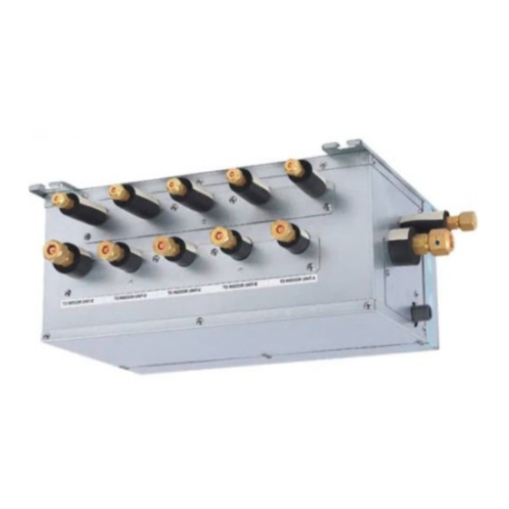
BRANCH BOX
[Service Ref.]
PAC-AK50BC
PAC-AK51BC
PAC-AK52BC
PAC-AK53BC
PAC-AK30BC
PAC-AK31BC
PAC-AK32BC
CONTENTS
1. SAFETY PRECAUTION ·······································
2. OVERVIEW OF UNIT ···········································
3. SPECIFICATIONS ················································
4. OUTLINES AND DIMENSIONS ···························
5. WIRING DIAGRAM ·············································
6. REFRIGERANT SYSTEM DIAGRAM ················· 11
7. TROUBLESHOOTING ········································
8. DISASSEMBLY PROCEDURE ···························
PARTS CATALOG (OCB508)
HFC
utilized
R410A
April 2013
No. OCH508
REVISED EDITION-A
Revision:
• PAC-AK53BC and PAC-
AK32BC have been added
in REVISED EDITION-A.
• Some descriptions have
been modified.
• Please void OCH508.
NOTE:
• This service manual
describes technical data of
branch box. As for indoor
units and outdoor unit,
refer to its service manual.
2
5
8
9
10
12
23
Advertisement
Table of Contents

Related Manuals for Mitsubishi Electric PAC-AK50BC


Summary of Contents for Mitsubishi Electric PAC-AK50BC
-
Page 1: Table Of Contents
R410A April 2013 No. OCH508 REVISED EDITION-A TECHNICAL & SERVICE MANUAL [Model name] [Service Ref.] Revision: <Branch box> PAC-AK50BC • PAC-AK53BC and PAC- AK32BC have been added PAC-AK50BC in REVISED EDITION-A. • Some descriptions have PAC-AK51BC been modified. PAC-AK51BC PAC-AK52BC •... -
Page 2: Safety Precaution
SAFETY PRECAUTION 1-1. ALWAYS OBSERVE FOR SAFETY Before obtaining access to terminal, all supply circuit must be disconnected. 1-2. CAUTIONS RELATED TO NEW REFRIGERANT Cautions for units utilizing refrigerant R410A Use new refrigerant pipes. Do not use refrigerant other than R410A. If other refrigerant (R22 etc.) is used, chlorine in refrige- Make sure that the inside and outside of refrige- rant can cause deterioration of refrigerant oil etc. - Page 3 [1] Cautions for service (1) Perform service after recovering the refrigerant left in unit completely. (2) Do not release refrigerant in the air. (3) After completing service, charge the cycle with specified amount of refrigerant. (4) When performing service, install a filter drier simultaneously. Be sure to use a filter drier for new refrigerant.
- Page 4 (2) Cautions for refrigerant piping work New refrigerant R410A is adopted for replacement inverter series. Although the refrigerant piping work for R410A is same as for R22, exclusive tools are necessary so as not to mix with different kind of refrigerant. Furthermore as the working pressure of R410A is 1.6 times higher than that of R22, their sizes of flared sections and flare nuts are different.
-
Page 5: Overview Of Unit
OVERVIEW OF UNIT 2-1. SYSTEM OUTLINE The additional connection of the Branch Box together with employment of the compact trunk-looking outdoor unit can successfully realizes a long distance piping for big houses. Equipped with a microprocessor, the Branch Box can trans- late the transmission signal of indoor units to achieve the optimum control. -
Page 6: Installation
2-2. INSTALLATION 2-2-1. Space required for Installation and servicing for Branch box. (1) Front View (Fig. 2-1) A Branch box B On the side of piping (2) Side View (Fig. 2-2, Fig. 2-3) C For indoor installations D Ceiling board E Maintenance hole F PCB side *1: A minimum 350 mm is required for 90°... - Page 7 2-3. SIMPLIFIED PIPING SYSTEM Piping connection size The piping connection size differs according to the type and capacity of indoor units. Liquid (mm) 9.52 Match the piping connection size of branch box with indoor unit. If the piping connection size of branch box does not match the piping connection size of indoor unit, use optional different-diameter (deformed) joints to the branch box side.
-
Page 8: Specifications
SPECIFICATIONS PAC-AK50BC PAC-AK51BC PAC-AK52BC PAC-AK53BC PAC-AK30BC PAC-AK31BC PAC-AK32BC PAC-AK50BC Model name PAC-AK30BC PAC-AK51BC PAC-AK31BC PAC-AK52BC PAC-AK32BC PAC-AK53BC MAX. 5 MAX. 3 Connectable number of indoor units Power supply (from outdoor unit) Single phase, 220/230/240V, 50Hz, Single phase, 220V, 60Hz Input 0.003... -
Page 9: Outlines And Dimensions
OUTLINES AND DIMENSIONS unit: mm PAC-AK50BC PAC-AK51BC PAC-AK52BC PAC-AK53BC SUSPENSION BOLT PITCH SUSPENSION BOLT : W3/8 (M10) REFRIGERANT PIPE FLARED CONNECTION (inch) TO OUTDOOR UNIT LIQUID PIPE GAS PIPE DRAIN HOSE SIZE : O.D. 20 (VP-16) 3-ELECTRIC WIRE INLET TERMINAL BLOCK... -
Page 10: Wiring Diagram
WIRING DIAGRAM PAC-AK50BC PAC-AK51BC PAC-AK52BC PAC-AK53BC PAC-AK30BC PAC-AK31BC PAC-AK32BC Note : " PAC - AK30 . 50BC, PAC - AK31 . 51BC, PAC-AK32 . 52BC, PAC-AK53BC " is only for R410A. SYMBOL NAME Branch box controller board <B.C> Fuse 250V 6.3A SW1<B.C>... -
Page 11: Refrigerant System Diagram
REFRIGERANT SYSTEM DIAGRAM ■ ■ PAC-AK50BC PAC-AK51BC PAC-AK30BC PAC-AK31BC PAC-AK52BC PAC-AK53BC PAC-AK32BC Thermistor (TH-A~E) Thermistor (TH-A~C) (Gas pipe temperature) (Gas pipe temperature) LEV A~E LEV A~C (Linear expansion valve) (Linear expansion valve) Strainer Strainer #100 #100 Strainer Strainer #100 #100... -
Page 12: Troubleshooting
TROUBLESHOOTING 7-1. HOW TO CHECK THE PARTS BRANCH BOX : PAC-AK50BC PAC-AK51BC PAC-AK52BC PAC-AK53BC PAC-AK30BC PAC-AK31BC PAC-AK32BC Parts name Check points Disconnect the connector then measure the resistance with a tester. Thermistor (TH-A~E) (At the ambient temperature 10 ~30 ) <Gas pipe>... - Page 13 Linear expansion valve (LEV) in Branch box (1) Operation summary of the linear expansion valve • Linear expansion valve open/close through stepping motor after receiving the pulse signal from the branch box controller board. • Valve position can be changed in proportion to the number of pulse signal. <Connection between the branch box controller board and the linear expansion valve>...
- Page 14 (3) How to attach and detach the coil of linear expansion valve <Composition> Linear expansion valve is separable into the main body and the coil as shown in the diagram below. Main body Coil Lead wire Stopper <How to detach the coil> Hold the lower part of the main body (shown as A) firmly so that the main body does not move and detach the coil by pulling it upward.
- Page 15 Troubleshooting Check point Corrective measure Problem Locked expansion Replace the linear If the linear expansion valve becomes locked and the motor is still operating, valve expansion valve. the motor will emit a clicking noise and will not function. This clicking noise indicates an abnormality.
-
Page 16: Test Point Diagram
7-2. TEST POINT DIAGRAM Branch box controller board PAC-AK50BC PAC-AK51BC PAC-AK52BC PAC-AK53BC PAC-AK30BC PAC-AK31BC PAC-AK32BC LED1 Transmission start-up state display TH-A to E Connect to LEV-A to E Start-up : LED1 blinks Thermistor-A to E Connect to LEV-A to E (0.5sec. -
Page 17: Function Of Switches
7-3. FUNCTION OF SWITCHES <Branch box unit operation monitor function> [When option part ‘A-Control Service Tool (PAC-SK52ST)’ is connected to branch box controller board (CNM)] Digital indicator LED1 displays 2 digit number or code to inform operation condition and the meaning of error code by controlling DIP SW2 on ‘A-Control Service Tool’. - Page 18 ■ The black square ( ) indicates a switch position. SW2 setting Display detail Explanation for display Unit LEV-B opening pulse 0 - 500 0 - 500 (When it is 100 pulse or more, hundreds digit, tens digit and ones digit are displayed by turns. Pulse (Example) 2 3 4 5 6...
- Page 19 ■ The black square ( ) indicates a switch position. SW2 setting Display detail Explanation for display Unit Indoor pipe temperature / Liquid – 35 - 88 (When the temperature is 0: or less, “–” and Indoor-B temperature are displayed by turns.) –...
- Page 20 ■ The black square ( ) indicates a switch position. SW2 setting Display detail Explanation for display Unit Outdoor heatsink temperature (TH8) – 40 - 200 – 40 - 200 (When the temperature is 0: or less, “–” and temperature are displayed by turns.) (When the thermistor detects 100: or more, hundreds digit, tens digit and ones digit are 2 3 4 5 6...
- Page 21 ■ The black square ( ) indicates a switch position. SW2 setting Display detail Explanation for display Unit Branch pipe temperature – 39 - 88 TH-A 2 3 4 5 6 Branch pipe temperature – 39 - 88 TH-B 2 3 4 5 6 Branch pipe temperature –...
- Page 22 ■ The black square ( ) indicates a switch position. SW2 setting Display detail Explanation for display Unit Indoor - setting temperature 16 - 31 16 - 31 Indoor-A 2 3 4 5 6 Indoor - setting temperature 16 - 31 16 - 31 Indoor-B 2 3 4 5 6...
-
Page 23: Disassembly Procedure
DISASSEMBLY PROCEDURE PAC-AK50BC PAC-AK51BC PAC-AK52BC PAC-AK53BC PAC-AK30BC PAC-AK31BC PAC-AK32BC Note: 1. Before disassembling/servicing the branch box, be sure to power off the outdoor unit. 2. Be careful of dropping of the panel or controller board during the service. 3. When servicing the parts associated with refrigerant, recover refrigerant in advance. - Page 24 Photo 5 Separator LEV coil Band HEAD OFFICE : TOKYO BLDG., 2-7-3, MARUNOUCHI, CHIYODA-KU, TOKYO100-8310, JAPAN cCopyright 2011 MITSUBISHI ELECTRIC CORPORATION Distributed in Apr. 2013 No.OCH508 REVISED EDITION-A Distributed in Jul. 2011 No.OCH508 New publication, effective Apr. 2013 Made in Japan...