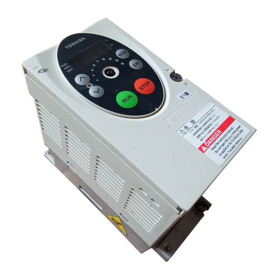
Toshiba TOSVERT VF-S11 Instruction Manual
Industrial inverter (for 3-phase induction motors)
Hide thumbs
Also See for TOSVERT VF-S11:
- Instruction manual (269 pages) ,
- Option instruction manual (22 pages) ,
- Specifications (12 pages)
Table of Contents
Advertisement
Industrial Inverter
(For 3-phase induction motors)
Instruction Manual
TOSVERT
< Simplified manual >
1-phase 240V class 0.2 to 2.2kW
3-phase 240V class 0.4 to 15kW
3-phase 500V class 0.4 to 15kW
3-phase 600V class 0.75 to 15kW
1.Make sure that this instruction manual is delivered to the
end user of the inverter unit.
2.Read this manual before installing or operating the inverter
unit, and store it in a safe place for reference.
S11
VF-
TM
NOTICE
E6581160
I
Safety
precautions
Contents
1
Read first
2
Connection
3
Operations
4
Basic VF-S11
operations
5
Monitoring the
operation status
6
Measures
to satisfy the
standards
7
Table of
parameters
and data
8
Specifications
9
Before making
a service call
9
Measures
to satisfy the
standards
10
Peripheral
devices
11
Table of
parameters
and data
12
Specifications
13
Before making a service
call - Trip information and
remedies
14
Inspection and
maintenance
15
Warranty
16
Disposal of the
inverter
2010 Ver. 118/119
Advertisement
Table of Contents

Related Manuals for Toshiba TOSVERT VF-S11


Summary of Contents for Toshiba TOSVERT VF-S11
-
Page 1: Industrial Inverter
E6581160 Safety precautions Contents Read first Industrial Inverter Connection (For 3-phase induction motors) Operations Basic VF-S11 operations Instruction Manual Monitoring the operation status Measures to satisfy the TOSVERT standards Table of parameters and data Specifications < Simplified manual > Before making... -
Page 2: I Safety Precautions
E6581160 Safety precautions The items described in these instructions and on the inverter itself are very important so that you can use the inverter safely, prevent injury to yourself and other people around you as well as to prevent damage to property in the area. -
Page 3: General Operation
E6581160 General Operation Warning • Never disassemble, modify or repair. This can result in electric shock, fire and injury. For repairs, call your sales distributor. Disassembly prohibited • Never remove the front cover when power is on or open door if enclosed in a cabinet. The unit contains many high voltage parts and contact with them will result in electric shock. - Page 4 Operation cannot be stopped immediately by the inverter alone, thus risking an accident or injury. • All options used must be those specified by Toshiba. The use of any other option may result in an accident.
- Page 5 E6581160 Warning • Electrical installation work must be done by a qualified expert. Connection of input power by someone who does not have that expert knowledge may result in fire or electric shock. • Connect output terminals (motor side) correctly. If the phase sequence is incorrect, the motor will operate in reverse and that may result in injury.
-
Page 6: Measures
E6581160 Operations Warning • Do not touch inverter terminals when electrical power is going to the inverter even if the motor is stopped. Touching the inverter terminals while power is connected to it may result in electric shock. • Do not touch switches when the hands are wet and do not try to clean the inverter with a damp cloth. Such practices may result in electric shock. -
Page 7: Maintenance And Inspection
E6581160 When sequence for restart after a momentary failure is selected (inverter) Caution • Stand clear of motors and mechanical equipment. If the motor stops due to a momentary power failure, the equipment will start suddenly after power recovers. This could result in unexpected injury. •... - Page 8 E6581160 Disposal Caution • If you dispose of the inverter, have it done by a specialist in industry waste disposal(*). If you dispose of the inverter in an inappropriate way, this can result in explosion of capacitor or produce noxious gases, resulting in injury. (*) Persons who specialize in the processing of waste and known as "industrial waste product collectors Instruction and transporters"...
- Page 9 E6581160 II. Introduction Thank you for your purchase of the Toshiba “TOSVERT VF-S11” industrial inverter. This manual is a simplified version. If you need a detailed explanation, refer to the full version of English manual (E6581158). This is the Ver. 118/ Ver. 119 CPU version inverter.
-
Page 10: Table Of Contents
2. Connection ..................................13 Standard connections ............................13 Description of terminals ............................. 15 3. Operations ..................................22 Simplified operation of the VF-S11 ........................22 How to operate the VF-S11..........................26 4. Basic VF-S11 operations ............................... 30 Flow of status monitor mode..........................31 How to set parameters............................ -
Page 11: Read First
If the inverter that is used does not conform to those specifications, not only will the three-phase induction motor not rotate correctly, it may also cause serious accidents Mandatory through overheating and fire. Inverter main unit Rating label Series name VF-S11 Power supply 1PH-200/240V-0.75kW/1HP Motor capacity Warning label Carton box Name plate... - Page 12 No part of the contents of the CD-ROM shall be reproduced without written permission from Toshiba Schneider Inverter Corporation. [Exclusions] Toshiba Schneider Inverter Corporation shall have no liability for any damage of any kind caused by the use of this CD- ROM.
-
Page 13: Specifications
E6581160 Contents of the product Explanation of the name plate label. Always shut power off first then check the ratings label of inverter held in a cabinet. Type Form V F S 11 S - 2 0 0 7 P L E - W N - A 2 2 Applicable motor Default interface Special specification code... -
Page 14: Connection
Power circuit 500V class: three-phase 380-500V T/L3 filter W/T3 -50/60Hz 600V class: three-phase 525-600V Forward Control -50/60Hz circuit Reverse Reset VF-S11 Protective function Preset-speed 1 MCCB(2P) Operation panel activation output Power supply R/L1 1 200~240V Preset-speed 2 Connector for -50/60Hz S/L2... -
Page 15: Standard Connection Diagram
-50/60Hz Power circuit filter T/L3 W/T3 500V class: three-phase 380-500V -50/60Hz Control 600V class: three-phase 525-600V -50/60Hz circuit Forward Reverse VF-S11 Protective function Reset MCCB(2P) Operation panel activation output Power supply R/L1 240V Preset-speed 1 -50/60Hz Connector for S/L2 common serial... -
Page 16: Description Of Terminals
E6581160 Description of terminals 2.2.1 Power circuit terminals In case of the lug connector, cover the lug connector with insulated tube, or use the insulated lug connector. Screw size tightening torque M3.5 screw 0.8Nm 7.1lb in M4 screw 1.2Nm 10.7lb in M5 screw 2.5Nm 22.3lb in... -
Page 17: Control Circuit Terminals
E6581160 Wire size (See Note 4) Capacity of Power circuit DC reactor Braking resistor/ Earth cable Voltage class applicable Inverter model ) (Note 1.) (optional) (mm Braking unit motor (kW) (optional) (mm (note 5) VFS11-4004PL 2.0 (2.0) 2.0 (2.5) 0.75 VFS11-4007PL 2.0 (2.0) 2.0 (2.5) - Page 18 E6581160 Control circuit terminals Terminal Electrical Input/output Function Inverter internal circuits symbol specifications Shorting across F-CC causes forward rotation; open causes slow- Input down and stop. (When ST is always No voltage Shorting across R-CC causes contact input reverse rotation; open causes slow- Input 24Vdc-5mA or less SINK...
- Page 19 E6581160 Terminal Electrical Input/output Function Inverter internal circuits symbol specifications Multifunction programmable analog input. Standard default setting: 0~10Vdc input and 0~60Hz (0~50Hz) frequency 10Vdc By changing parameter setting, this Input (internal terminal can also be used as a impedance: 30kΩ) multifunction programmable contact input terminal.
- Page 20 E6581160 Terminal Electrical Input/output Function Inverter internal circuits symbol specifications +24V Multifunction programmable relay contact 250Vac-1A output. (cosφ=1) Standard default settings detect and : at resistance load Output output low-speed signal output 30Vdc-0.5A frequencies. 250Vac-0.5A Multifunction output terminals to which two (cosφ=0.4) different functions can be assigned.
- Page 21 E6581160 SINK (Negative) logic/SOURCE (Positive) logic (When an external power supply is used) The PLC terminal is used to connect to an external power supply or to insulate a terminal from other input or output terminals. As for input terminals, turn the SW1 slide switch to the PLC position. <Examples of connections when an external power supply is used>...
- Page 22 E6581160 ★ The examples of connection are shown below when VIA and VIB are used as contact input terminals. The figure is for sink logic mode. The figure is for source logic mode. Logic switching/Voltage-current output switching (slide switch) Logic switching Use SW1 to switch between logics.
-
Page 23: Operations
E6581160 3. Operations Simplified Operation of the VF-S11 The procedures for setting operation frequency and the methods of operation can be selected from the following. : (1) Start and stop using the operation panel keys Start / Stop (2) Run and stop using external signals to terminal... - Page 24 E6581160 3.1.1 How to start and stop [Example of a setting procedure] Key operated LED display Operation Displays the operation frequency (operation stopped). (When standard monitor display selection = [Operation frequency]) Displays the first basic parameter [History ()]. MODE ...
- Page 25 E6581160 3.1.2 How to set the frequency [Example of a setting procedure] Key operated LED display Operation Displays the operation frequency (operation stopped). (When standard monitor display selection = [Operation frequency]) Displays the first basic parameter [History ()]. MODE ...
-
Page 26: Frequency Setting
E6581160 (3) Setting the frequency using external signals to terminal board (= or ) Frequency setting Setting the frequency using external potentiometer ★Potentiometer Setting frequency using the potentiometer (1k-10kΩ, 1/4W) : Setting frequency 60Hz using potentiometer Frequency * The input terminal VIA can be used in the same way. =: VIA effective, =: VIB effective Setting the frequency using input voltage (0~10V) ★Voltage signal... -
Page 27: How To Operate The Vf-S11
E6581160 How to operate the VF-S11 Overview of how to operate the inverter with simple examples. Setting the operation frequency using built-in potentiometer and Ex.1 running and stopping using the operation panel. Wiring PA/+ PC/- Motor MCCB R/L1 U/T1 S/L2... - Page 28 E6581160 Setting the operation frequency using the operation panel and Ex.2 running and stopping using the operation panel. Wiring PA/+ PC/- Motor MCCB R/L1 U/T1 S/L2 V/T2 Noise Power circuit T/L3 filter W/T3 Braking circuit Parameter setting Title Function Programmed value Command mode selection ...
- Page 29 E6581160 Setting the operation frequency using built-in potentiometer and Ex.3 running and stopping using external signals. Wiring PA/+ PC/- Motor MCCB R/L1 U/T1 S/L2 V/T2 Noise Power circuit filter T/L3 W/T3 Braking Run forward circuit signal backward signal Common Parameter setting Title Function Programmed value...
- Page 30 E6581160 Operation frequency setting, running and stopping using external Ex.4 signals. Wiring PA/+ PC/- Motor MCCB R/L1 U/T1 S/L2 V/T2 Noise Power circuit T/L3 W/T3 filter Run forward signal Braking circuit Run backward signal Common Current signal: 4∼20mA Voltage signal: 0∼10V External potentiometer (Otherwise, input voltage signal (0~10V) between the terminals VIA-CC.) Parameter setting...
-
Page 31: Basic Vf-S11 Operations
E6581160 4. Basic VF-S11 operations The VF-S11 has the following four monitor modes. : The standard inverter mode. This mode is enabled when Standard monitor mode inverter power goes on. This mode is for monitoring the output frequency and setting the frequency designated value. -
Page 32: Flow Of Status Monitor Mode
E6581160 Flow of status monitor mode Status monitor mode Flow of monitor as following Setting monitor mode f60.0 MODE MODE Standard monitor mode Display mode 28 kinds of data 60.0 fr-f t0.10 MODE n<> 10 kinds of data Data of 4 times. oc1 4 op3 3 t8.56... -
Page 33: How To Set Parameters
E6581160 How to set parameters The standard default parameters are programmed before the unit is shipped from the factory. Parameters can be divided into 4 major categories. Select the parameter to be changed or to be searched and retrieved. : The basic parameters that must be programmed Basic parameters before the first use. - Page 34 E6581160 4.2.1 How to set the basic parameters All of the basic parameters can be set by the same step procedures. [Steps in key entry for basic parameters] * Parameters were factory-set by default Switches to the setting monitor mode. MODE before shipment.
-
Page 35: How To Set Extended Parameters
E6581160 4.2.2 How to set extended parameters The VF-S11 has extended parameters to allow you to make full use of its functions. All extended parameters are expressed with and three digits. Basic parameters ~ MODE Press the key or the... - Page 36 E6581160 Example of parameter setting Steps in setting are as follows (Example of changing the dynamic braking selection from 0 to 1.) Key operated LED display Operation Displays the operation frequency (operation stopped). (When standard monitor display selection = [Operation ....
- Page 37 E6581160 Key operated LED display Operation Press the ENTER key to enable the user parameter automatic edit function. Searches for parameters that are different in value from the standard default setting and displays those parameters. Press the ENTER key ()...
- Page 38 E6581160 How to use the history function Key operated LED display Operation Displays the operation frequency (operation stopped). (When standard monitor display selection = [Operation frequency]) The first basic parameter “” (history function) is displayed. MODE The parameter that was set or changed last is displayed. ...
- Page 39 E6581160 4.2.6 Returning all parameters to standard default setting Setting the standard default setting parameter =, all parameters can be returned to the those factory default settings. Note: For more details on the standard default setting parameter , see 5.6. Notes on operation •...
-
Page 40: Monitoring The Operation Status
E6581160 5. Monitoring the operation status Refer to 4.1 about flow of monitor. Status monitor mode 5.1.1 Status monitor under normal conditions In this mode, you can monitor the operation status of the inverter. To display the operation status during normal operation: Press the key twice. - Page 41 E6581160 (Continued) Communic Item displayed Description operated display ation No. The ON/OFF status of each of the control signal input terminals (F, R, RES, S1, S2, S3, VIB and VIA) is displayed in bits. }}}ii}ii ON: OFF: Input terminal FE06 Note 4 }}}ii}ii...
- Page 42 E6581160 (Continued) Communic Item displayed Description operated display ation No. Note 7 ⇔ Past trip 4 FE13 Past trip 4 (displayed alternately) The ON/OFF status of each of the cooling fan, circuit board capacitor, main circuit capacitor of parts replacement alarm or cumulative operation time are displayed in bits.
-
Page 43: Display Of Detailed Information On A Past Trip
E6581160 5.1.2 Display of detailed information on a past trip Details on a past trip (of trips 1 to 4) can be displayed, as shown in the table below, by pressing the when the trip record is selected in the status monitor mode. Unlike the "Display of detailed trip information at the occurrence of a trip"... -
Page 44: Display Of Trip Information
E6581160 Display of trip information 5.2.1 Trip code display If the inverter trips, an error code is displayed to suggest the cause. Since trip records are retained, information on each trip can be displayed anytime in the status monitor mode. For the kinds of causes that can be indicated in the event of a trip, see section 9.1. - Page 45 E6581160 (Continued) Communic Item displayed Description operated display ation No. The ON/OFF statuses of the control input terminals (F, R, RES, S1, S2, S3, VIB and VIA) are displayed in bits. }}}ii}ii ON: Input terminal FE06 OFF: Note 4 } } } i i } i i The ON/OFF status of each of the control signal output terminals (RY, OUT and FL) at the...
- Page 46 E6581160 (Continued) Communic Item displayed Description operated display ation No. The ON/OFF status of each of the cooling fan, circuit board capacitor, main circuit capacitor of parts replacement alarm or cumulative operation time are displayed in bits. ON: Note 8 Parts replacement OFF: ...
- Page 47 E6581160 Note 9: The cumulative operation time increments only when the machine is in operation. Note 10: At the occurrence of a trip, maximum values are not always recorded and displayed for reasons of detecting time. Note 11: If there is no trip record, nerr is displayed. Of the items displayed on the monitor, the reference values of items expressed in percent are listed below.
-
Page 48: Measures To Satisfy The Standards
Inverters themselves are not subject to approval for CE marking. The CE mark must be put on every final product that includes an inverter(s) and a motor(s). The VF-S11 series of inverters complies with the EMC directive if an EMC filter recommended by Toshiba is connected to it and wiring is carried out correctly. -
Page 49: Measures To Satisfy The Emc Directive
E6581160 Table 1 EMC standards Product Category Subcategory Test standard standards Radiation noise CISPR11 (EN55011) Emission Transmission noise CISPR11 (EN55011) Static discharge IEC61000-4-2 Radioactive radio-frequency IEC61000-4-3 magnetic contactor field IEC 61800-3 First transient burst IEC61000-4-4 Immunity Lightning surge IEC61000-4-5 Radio-frequency IEC61000-4-6 induction/transmission interference Voltage dip/Interruption of power... - Page 50 With a built-in filter EMFS11S-2022CZ Note : For 600V models compliant with EU standards, contact your nearest Toshiba inverter distributor. Use shielded power cables, such as inverter output cables, and shielded control cables. Route the cables and wires so as to minimize their lengths. Keep a distance between the power cable and the control cable and between the input and output wires of the power cable.
- Page 51 6.1.3 About the low-voltage directive The low-voltage directive provides for the safety of machines and systems. All Toshiba inverters are CE-marked in accordance with the standard EN 50178 specified by the low-voltage directive, and can therefore be installed in machines or systems and imported without problem to European countries.
-
Page 52: Compliance With Ul Standard And Csa Standard
Install a non-fuse circuit breaker or a fuse on the input side of the inverter. Compliance with UL Standard and CSA Standard The VF-S11 models, that conform to the UL Standard and CSA Standard have the UL/CSA mark on the nameplate. - Page 53 E6581160 6.2.3 Compliance with Peripheral devices Use the UL listed fuses at connecting to power supply. Short circuit test is performed under the condition of the power supply short-circuit currents in below. These interrupting capacities and fuse rating currents depend on the applicable motor capacities. Refer to the table “AIC, Fuse and Wire sizes”...
- Page 54 E6581160 AIC, Fuse and Wire sizes Capacity of Voltage AIC (A) Fuse class and current Wire sizes of applicable motor Inverter model class (Interrupting capacity) power circuit (kW) VFS11S-2002PL AIC 1000A CC/J 6A max. AWG 14 VFS11S-2004PL AIC 1000A CC/J 10A max. AWG 14 Single-phase 0.75...
-
Page 55: Table Of Parameters And Data
E6581160 7. Table of parameters and data For details on the function of each parameter, refer to the full version of English manual (E6581158). User parameters Minimum setting unit User Reference Title Function Unit Adjustment range Default setting Panel/Comm setting E6581158 unication Operation... - Page 56 E6581160 Minimum Communication setting unit Default User Reference Title Function Unit Adjustment range Panel/Commun setting setting E6581158 ication 0005 Meter selection 0: Output frequency 1: Output current 2: Set frequency 3: DC voltage 4: Output voltage command value 5: Input power 6: Output power 7: Torque 8: Torque current...
- Page 57 E6581160 Minimum Communication setting unit Default User Reference Title Function Unit Adjustment range Panel/Commun setting setting E6581158 ication 0015 V/F control mode 0: V/F constant 5.11 selection 1: Variable torque 2: Automatic torque boost control 3: Vector control 4: Energy-saving 5: Dynamic energy-saving (for fans and pumps) 6: PM motor control...
-
Page 58: Extended Parameters
E6581160 Extended parameters • Input/output parameters 1 Minimum Communication setting unit Default User Reference Title Function Unit Adjustment range Panel/Commun setting setting E6581158 ication 0100 Low-speed signal 0.1/0.01 0.0- 6.1.1 output frequency 0101 Speed reach 0.1/0.01 0.0- 6.1.3 setting frequency 0102 Speed reach... - Page 59 E6581160 Minimum Communication setting unit Default User Reference Title Function Unit Adjustment range Panel/Commun setting setting E6581158 ication 0139 Output terminal 0: and 6.3.4 logic selection and (RY-RC, OUT-NO) 1: or and 2: ...
- Page 60 E6581160 Minimum Communication setting unit Default User Reference Title Function Unit Adjustment range Panel/Commun setting setting E6581158 ication 0210 VIB input point 1 0-100 6.5.2 setting 0211 VIB input point 1 0.1/0.01 0.0-500.0 frequency 0212 VIB input point 2 0-100 ...
- Page 61 E6581160 Minimum Communication setting unit Default User Reference Title Function Unit Adjustment range Panel/Commun setting setting E6581158 ication 0273 Jumping width 2 0.1/0.01 0.0-30.0 6.10 0274 Jump frequency 3 0.1/0.01 0.0- 0275 Jumping width 3 0.1/0.01 0.0-30.0 0287 Preset-speed 0.1/0.01...
- Page 62 E6581160 Minimum Communication setting unit Default User Reference Title Function Unit Adjustment range Panel/Commun setting setting E6581158 ication 0307 Supply voltage 0: Supply voltage uncorrected, output 6.13.6 correction voltage limited (WP, WN) (limitation of 3 (AN) 1: Supply voltage corrected, output output voltage) voltage limited 2: Supply voltage uncorrected, output...
- Page 63 E6581160 • Torque boost parameters 1 Minimum Communication setting unit Default User Reference Title Function Unit Adjustment range Panel/Commun setting setting E6581158 ication 0400 Auto-tuning 5.11 0: Auto-tuning disabled 6.17.1 1: Initialization of (reset to 0) 2: Auto-tuning enabled (after execution: 0) 0401 Slip frequency...
- Page 64 E6581160 Minimum Communication setting unit Default User Reference Title Function Unit Adjustment range Panel/Commun setting setting E6581158 ication 0496 Waveform 0.1/0.01 0.1-14.0 5.11 switching 6.17.2 adjustment coefficient 0497 Limiting function 0: Disabled of starting current 1: Enabled *1 : Default values vary depending on the capacity. See the table of page 68. •...
- Page 65 E6581160 Minimum Communication setting unit Default User Reference Title Function Unit Adjustment range Panel/Commun setting setting E6581158 ication 0604 Emergency DC 0.1/0.1 0.0-20.0 6.19.4 braking time Output phase 0: Disabled 0605 6.19.5 failure detection 1: At start-up (only one time after mode selection power is turned on) 2: At start-up (each time)
- Page 66 E6581160 Minimum Communication setting unit Default User Reference Title Function Unit Adjustment range Panel/Commun setting setting E6581158 ication 0634 Annual average 1: -10 to +10°C 6.19.14 ambient 2: 11-20°C temperature (parts 3: 21-30°C replacement 4: 31-40°C alarms) 5: 41-50°C 6: 51-60°C *1 : Default values vary depending on the capacity.
- Page 67 E6581160 • Operation panel parameters Minimum Communication setting unit Default User Reference Title Function Unit Adjustment range Panel/Commun setting setting E6581158 ication 0700 Prohibition of 0: Permitted 6.21.1 change of 1: Prohibited parameter settings 0701 Unit selection 0: % 6.21.2 ...
-
Page 68: Communication Parameters
0.1/0.01 0.0-500.0 50.0 (WP) command point 2 60.0 frequency (WN, AN) 0829 Selection of 0: Toshiba inverter protocol 6.22 communication 1: Modbus RTU protocol protocol 0870 Block write data 1 0: No selection 1: Command information 1... - Page 69 E6581160 Minimum Communication setting unit Default User Reference Title Function Unit Adjustment range Panel/Commun setting setting E6581158 ication 0890 Parameter for 0-65535 6.23 option 1 0891 Parameter for 0-65535 option 2 0892 Parameter for 0-65535 option 3 0893 Parameter for 0-65535...
- Page 70 E6581160 Default settings by inverter rating Dynamic Dynamic Automatic Motor Over-voltage Torque boost Motor rated Motor no-load Inverter type braking braking resistor torque boost adjustment stall protection value 1/2 current current resistance capacity value coefficient level ...
- Page 71 E6581160 Table of input terminal functions 1 Function Code Function Action No function is assigned Disabled Standby terminal ON: Ready for operation OFF: Coast stop (gate off) Forward run command ON: Forward run OFF: Slowdown stop Reverse run command ON: Reverse run OFF: Slowdown stop Jog run mode ON: Jog run, OFF: Jog run canceled Acceleration/deceleration 2 pattern selection...
- Page 72 E6581160 Table of input terminal functions 2 Function Code Function Action F+SS3+AD2 Combination of forward run, preset-speed ON: Simultaneous input from F, SS3 and AD2 command 3 and acceleration/deceleration 2 R+SS3+AD2 Combination of reverse run, preset-speed ON: Simultaneous input from R, SS3 and AD2 command 3 and acceleration/deceleration 2 F+SS4+AD2 Combination of forward run, preset-speed...
- Page 73 E6581160 Table of input terminal functions 3 Function Code Function Action Coast stop (gate off) ON: Coast stop (gate off) RESN Inversion of RES ON: Acceptance of reset command OFF→ ON: Trip reset F+ST Combination of forward run and standby ON: Simultaneous input from F and ST R+ST Combination of reverse run and standby...
- Page 74 E6581160 Table of output terminal functions 1 Function Code Function Action Frequency lower limit ON: The output frequency is above the set value. OFF: The output frequency is equal to or less than the set value. Inversion of frequency lower limit Inversion of LL setting Frequency upper limit ON: Output frequency is equal to or higher than...
- Page 75 E6581160 Table of output terminal functions 2 Function Code Function Action Pre-alarm One of the following is turned on: ON POL, POHR, POT, MOFF, UC, OT, LL stop, COT, and momentary power failure slowdown stop. or ,, issues an alarm All the following are turned off: OFF POL, POHR, POT, MOFF, UC, OT, LL stop, COT, and momentary power failure...
- Page 76 E6581160 Table of output terminal functions 3 Function Code Function Action LTAN Inversion of replacement alarm Inversion of LTA Braking sequence output ON: Braking retention signal OFF: Braking release signal Inversion of braking sequence output Inversion of BR F terminal input signal ON: The signal input to F terminal is ON OFF: The signal input to F terminal is OFF LI1N...
-
Page 77: Specifications
E6581160 8. Specifications Models and their standard specifications Standard specifications Item Specification Input voltage 3-phase 240V Applicable motor (kW) 0.55 0.75 Type VFS11 Form 2002PM 2004PM 2005PM 2007PM 2015PM 2022PM 2037PM 2055PM 2075PM 2110PM 2150PM Capacity (kVA) Note 1) Rated output current 11.0 17.5 27.5... - Page 78 E6581160 Note 1. Capacity is calculated at 220V for the 240V models, at 440V for the 500V models and at 575V for the 600V models. Note 2. Indicates rated output current setting when the PWM carrier frequency (parameter f300) is 4kHz or less. When exceeding 4kHz, the rated output current setting is indicated in the parentheses.
- Page 79 20 to 93% (free from condensation and vapor). Note 1. Above 40°C : Remove the protective seal from the top of VF-S11. If the ambient temperature is above 50°C: Remove the seal from the top of the inverter and use the inverter with the rated output current reduced.
-
Page 80: Outside Dimensions And Mass
E6581160 Outside dimensions and mass Outside dimensions and mass Applicable motor Dimensions (mm) Approx. weight Voltage class Inverter type Drawing (kW) (kg) VFS11S-2002PL VFS11S-2004PL 121.5 1-phase 240V 0.75 VFS11S-2007PL VFS11S-2015PL VFS11S-2022PL VFS11-2002PM VFS11-2004PM 0.55 VFS11-2005PM 121.5 0.75 VFS11-2007PM VFS11-2015PM 3-phase 240V VFS11-2022PM VFS11-2037PM VFS11-2055PM... -
Page 81: Outline Drawing
E6581160 Outline drawing R2.5 (Installation dimension) (Installation dimension) R2.5 VF-S11 VF-S11 4-M4 4-M4 EMC plate EMC plate Fig.A Fig.B Note 1. To make it easier to grasp the dimensions of each inverter, dimensions common to all inverters in 2-f25 these figures are shown with numeric values but not with symbols. - Page 82 E6581160 160(Installation dimension) 2-R2.5 VF-S11 4-M4 EMC plate Fig.D 225 (Installation dimension) 2-R3 VF-S11 4-M4 EMC plate Fig.E...
-
Page 83: Before Making A Service Call - Trip Information And Remedies
When a problem arises, diagnose it in accordance with the following table. If it is found that replacement of parts is required or the problem cannot be solved by any remedy described in the table, contact your Toshiba dealer. [Trip information]... - Page 84 E6581160 (Continued) Error code Failure code Problem Possible causes Remedies 000A Overvoltage during • The imput voltage fluctuates abnormally. • Insert a suitable input reactor. acceleration (1) The power supply has a capacity of 200kVA or more. (2) A power factor improvement capacitor is opened or closed.
- Page 85 E6581160 (Continued) Error code Failure code Problem Possible causes Remedies 002E External thermal trip • An external thermal trip is input. • Check the external thermal input. 0011 Emergency stop • During automatic operation or remote • Reset the inverter. operation, a stop command is entered from the operation panel or a remote input device.
- Page 86 E6581160 [Alarm information] Each message in the table is displayed to give a warning but does not cause the inverter to trip. Error code Problem Possible causes Remedies • The ST-CC circuit is opened. • Close the ST-CC circuit. ST terminal OFF ...
- Page 87 Pudong New Area, Shanghai 200120, The People's Republic of China TEL: +86-(0)21-6841-5666 FAX: +86-(0)21-6841-1161 For further information, please contact your nearest Toshiba Liaison Representative or International Operations - Producer Goods. The data given in this manual are subject to change without notice. 2010-7...