Advertisement
Quick Links
FH-RT Wireless Room Thermostat
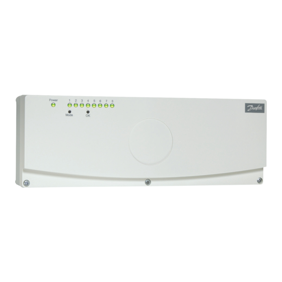
FH-BU Wireless Base Unit
Installation & Operating Instructions
Specification
Base unit (230 V)
Order Code:
Primary voltage:
Secondary voltage:
Outputs 1-6:
Outputs 7-8:
Max. no. of thermostats:
Max. no. of thermal actuators:
Max. no. of thermal actuators
per output:
Output 8 run-on time:
Thermal actuator & pump exercise
Settings after power failure:
Enclosure:
Dimensions [mm]
Ambient temperature:
Humidity:
Thermostat
Order Code:
Temperature scale:
Hysteresis:
Scale accuracy:
Night set-back:
Frequency:
Battery life:
Battery type:
Transmission range:
Transmission interval:
Ambient temperature:
Humidity:
System Schematic
088H011901
230 V a.c.
230 V a.c.
230 V a.c., 1 A max., relay
controlled
8 A, 230 V a.c./50 Hz, relay
controlled, convertible to
volt-free outputs
8 (wireless)
20
4
10 min
Once daily (approx. every 24
hours after connecting the
power supply for the first
time)
User settings are retained
IP20
310 x 110 x 55
0-50°C
Less than 85%
088H012100
6-30°C +/- 2K
+/- 0.5°C
2K around set point
4K at 20°C
433.70 MHz
Min. 5 years
3.6 V lithium battery, 2100
mAh, size AA
Up to 30 m (radius)
2-30 min
0-50°C
Less than 90%
Power
1
2
3
4
5
6
7
8
Mode
OK
80 mm
20
10
60 mm
30 mm
30
80 mm
1
Advertisement

Related Manuals for Danfoss FH-RT


Summary of Contents for Danfoss FH-RT
- Page 1 FH-RT Wireless Room Thermostat FH-BU Wireless Base Unit Installation & Operating Instructions Specification Base unit (230 V) Power Order Code: 088H011901 Mode Primary voltage: 230 V a.c. Secondary voltage: 230 V a.c. Outputs 1-6: 230 V a.c., 1 A max., relay...
-
Page 2: Operating Principle
These installation and operating instructions describe system function and technical data. The system is a complete floor heating control system for individual rooms in dwellings, offices, institutions, business premises, etc. The system is based on data transfer via radio, and is therefore quick and easy to install. The system was developed to meet requirements for comfort, heat economy, flexibility and user-friendly operation. -
Page 3: Installation Instructions
3.0 Installation instructions 4.0 Operating instructions 4.1 Thermal actuator installation The system should be installed by a competent person in the following sequence. Ensure that the power supply to the base unit is disconnected. Lift base unit cover after loosening front screws. 3.1 Base unit Remove internal aerial. - Page 4 4.3 Thermostat registration To get the FH-BU base into registration mode Press and hold “MODE” and “OK” buttons on base unit for 3 seconds, (all LED’s will flash) then release “MODE” and finally release “OK”. The system is now in registration mode.
- Page 5 If no signal is received from one or more thermostats, the corresponding If after a further 8 hours the base unit has still not received a signal from the LEDs on the indicator panel remain lit. thermostat, an acoustic alarm begins buzzing. The buzzer can be de-activated When the required number of thermostats have been checked, press and by selecting the alarm “OFF”...
- Page 6 8/pump (optional) Danfoss Randall can accept no responsibilty for possible errors in catalogues, brochures and other printed material. Danfoss Randall reserves the right to alter its products without notice. This also applies to products already on order provided that such alterations can be made without subsequent changes being necessary in specifications already agreed.