Table of Contents
Advertisement
Advertisement
Table of Contents

Subscribe to Our Youtube Channel
Related Manuals for JBL CSM 14


Summary of Contents for JBL CSM 14
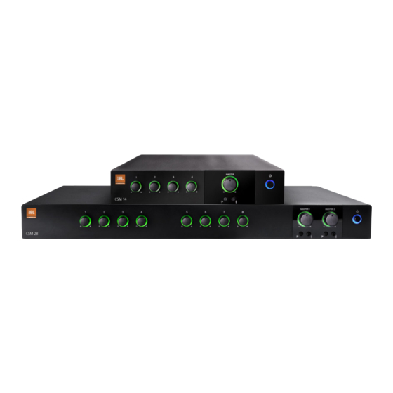
- Page 1 JBL Commercial Series CSM 14 CSM 28 Commercial Series Mixer Operation Manual...
-
Page 2: Table Of Contents
The information provided in this manual was deemed accurate as of the publication date. However, updates to this information may have occured. Trademark Notice: JBL is registered trademark of JBL International. CROWN and DRIVECORE are registered trademarks of Crown Audio. Other trademarks are the property of their respective owners. -
Page 3: Important Safety Instructions
IMPORTANT SAFETY INFORMATION WARNING FOR YOUR PROTECTION READ THE FOLLOWING: KEEP THESE INSTRUCTIONS HEED ALL WARNINGS FOLLOW ALL INSTRUCTIONS THE APPARATUS SHALL NOT BE EXPOSED TO DRIPPING OR SPLASHING LIQUID AND NO OBJECT FILLED WITH LIQUID, SUCH AS VASES, SHALL BE PLACED ON THE APPARATUS The symbols shown above are internationally accepted symbols that warn of potential hazards with electrical products. - Page 4 IMPORTANT SAFETY INFORMATION U.K. MAINS PLUG WARNING If you want to dispose this product, do not mix it with gen- eral household waste. There is a separate collection system for used electronic products in accordance with legislation A molded mains plug that has been cut off from the cord is that requires proper treatment, recovery and recycling.
-
Page 5: Jbl Declaration Of Conformity
EC - DECLARATION OF CONFORMITY Brand: Equipment Type: Commercial Audio Mixer Model names: CSM 14, CSM 28 We, Harman International, declare under our sole responsibility that the product, to which this declaration relates, is in conformity with the following standards. Report No. Description EN 55103-1:2009 EMC Compatibility –... -
Page 7: Welcome
The product includes a rack mounting kit for installations to a cabinet. The system can be easily expanded with additional JBL Commercial Series Amplifiers and Com- mercial Series Mixer-amplifiers. Provisions are included for a remote volume control using the JBL CSR-V control module. -
Page 8: Front Control Panels And Indicators
1.2 Front Panel Controls and Indicators Figure 1.2 Front View CSM 14 A. Input Level Controls B. Input signal presence is indicated by green illumination of the ring around the input level controls C. Output Volume Controls D. Power Switch E. -
Page 9: Rear Panel Controls And Connectors - Four Channel
G. VOX Adjustment - allows the input level to be set that will invoke priority override. (Ch1) H. Line Level Output Connector Remote Volume connector – RJ45 style connector to connect to a JBL CSR-V control module. Mic/Line Input Connector - 3-pin Euro-block connector, balanced input (Ch... -
Page 10: Rear Panel Controls And Connectors - Eight Channel
Priority Input Connector – 5-pin Euro-block includes 3 pins for a balanced input as well as two pins that, when shorted together, activates the priority function. (Ch 1 & 5) Remote Volume Control – RJ45 style connector to connect to a JBL CSR-V control module. - Page 11 LINE LINE LINE MONO SUM MONO SUM MONO SUM PRIORITY CH 1 VOX LINE LINE LINE CH 5 VOX PRIORITY MONO SUM MONO SUM MONO SUM G. Line Out – Line level output connector for each output channel. H. Mic/Line Input Connector – 3-pin Euro-block connector for a balanced input source.
-
Page 12: Important Safety Instructions
2.0 Setup 2.1 Unpacking Your Unit Please unpack and inspect your unit for any damage that may have occurred during transit. If damage is found, notify the transportation company immediately. Only you can initiate a claim for shipping damage. We will be happy to help as needed. Save the shipping carton as evidence of damage for the shipper’s inspection. - Page 13 Figure 2.2.1 Dimensions CSM 14 218.44 mm [8.6 in] 303.4 mm [11.9 in] CSM 28 436.88 mm [17.2 in] 303.4 mm [11.9 in] Figure 2.2.2 Mounting Kit long angle bracket (CSM 14 only) flat bracket (CSM 14 only) front angle bracket...
- Page 14 Figure 2.2.3 Rack Mounting Two Half-rack Mixers Solution A: Rack Mounting Two Half-rack Mixers To install two half-rack width units in your cabinet system, refer to Figure 2.2.3 and follow the steps below: Align two modules side by side and upside down with the front panel towards the same direction.
- Page 15 Figure 2.2.4 Rack Mounting A Single Half-rack Mixer Solution B: Rack Mounting A Single Half-rack Mixer To install a single half-rack unit, refer to Figure 2.2.4 and follow the steps below: Determine which side of the rack opening will be used for the mixer and attach the long angle bracket to the other side at the front using the screws provided.
- Page 16 Figure 2.2.5 Rack Mounting A Full-rack Mixer Solution C: Rack Mounting Full Rack Mixer To install a full-rack width unit, refer to Figure 2.2.5 and follow the steps below: Attach the front angle brackets to each side of the front of the unit using the screws provided.
-
Page 17: Choosing Wire And Connectors
Figure 2.3 Input and Output Wiring INPUT CONNECTOR OUTPUT CONNECTOR MONO SUM AUDIO AUDIO SOURCE SOURCE AUDIO OUTPUT AUDIO AUDIO SOURCE SOURCE Note: Two RCA connectors are provided for summing left and right channels from a stereo source. Do not use both Euroblock and RCA connectors concurrently for any single input channel. -
Page 18: Wiring Your Audio System
INPUTS: Connect input wiring for both channels using either the RCA or the Euroblock input for each channel. OUTPUTS: The mixer’s line level output may be connected to the input of a power amplifer such as a JBL Commercial Series Amplifer. -
Page 19: Connecting To Ac Mains
2.5 Connecting to AC Mains Connect your mixer to the AC mains power source (power outlet) with the supplied AC power cord. First, connect the IEC end of the cord set to the IEC connector on the mixer; then, plug the other end of the cord set to the AC mains. When properly connected to a live power source, the power ring should illuminate with a green color. -
Page 20: Operation
Such signals will be reproduced with extreme accuracy, and loudspeaker damage may result. Use the unit in a well-ventilated environment and do not use it in ambient temperature conditions in excess of 40°C. CAUTION: JBL is not liable for damage that results from overdriving other system components. -
Page 21: Input Routing
VOX function. 3.5 Priority Muting With CSM 14 Input Channel 1 may be used as a priority channel, muting all other channels when pin 4 and pin 5 are shorted using a switch closure. CSM 28 units let Input Ch1 operate with priority over all inputs into OUT 1. Ch1 will have priority over both OUT 1 and OUT 2 if the routing DIP switch #1 is set to ON. -
Page 22: Troubleshooting
4.0 Troubleshooting CONDITION: No power to the mixer so that the power ring is not illuminated. POSSIBLE REASON: The mixer is not plugged into the power receptacle. CONDITION: No sound or low sound. POSSIBLE REASON: The input signal is not present or at a very low level. POSSIBLE REASON: The Master Volume control is turned down. -
Page 23: Appendix A: Target Performance Specifications
Appendix A: Target Performance Specifications Performance CSM 14 CSM 28 Number of Input Channels Number of Output Channels Line Output level 5.0V into 10kΩ Input Sensitivity to obtain 5V to line out Mic Input: 3mV Line Input: 775 mV RCA Input: 300mV... -
Page 24: Appendix B: Block Diagram
Appendix B : Block Diagram CSM 28 Block Diagram CSM28 Block Diagram Phantom Power (SW6) Input Gain Line Mic/Line [Bal] CH1 TO AMP1 Gain 1 ∑ CH1 TO AMP2 CH1 VOX CH1 Priority CH1 PTT Input Gain Line CH2 TO AMP1 ∑... - Page 25 Clip 1 SPI 1 Tone Control Line Out 1 Bass Treble (SW5) Master 1 Scaling VCA 1 SPI 2 Clip 2 Line Out 2 Tone Control Treble Bass (SW11) Master 2 VCA 2 Scaling...
-
Page 26: Appendix C: Contact Information
For additional information, please consult JBL Professional Customer Service, your system installer or retailer. On The World Wide Web: www.jblcommercialproducts.com Professional Contacts, Outside the USA: Contact the JBL Professional Distributor in your area. A complete list of JBL Professional international distributors is provided at our U.S.A. Website: www.jblpro.com... - Page 28 JBL Commercial 8760 South Sandy Pkwy. Sandy, UT 84070 USA (801) 566-8800 Part Number: 5040964 Issue: 01/14...
Need help?
Do you have a question about the CSM 14 and is the answer not in the manual?
Questions and answers