
Subscribe to Our Youtube Channel
Related Manuals for LG LD-1415M1


Summary of Contents for LG LD-1415M1
- Page 1 DISHWASHER SERVICE MANUAL NOTE BEFORE SERVICING THE UNIT, PLEASE READ THIS MANUAL CAREFULLY FOR SAFETY AND CORRECT SERVICES. MODEL : LD-1415M1 / LD-1415T1 / LD-1415W1...
- Page 2 - 3 -...
-
Page 3: Table Of Contents
CONTENTS 1. CAUTION......................... 4 2. SPECIFICATIONS ......................5 3. PARTS NAME ........................6 4. FEATURES & TECHNICAL EXPLANATION ..............7 5. WIRING DIAGRAM...................... 14 6. PROGRAM CHART (SCHEMATIC DIAGRAM) ............15 7. HOW TO DISASSEMBLE .................... 19 8. TROUBLE SHOOTING METHODS ................29 A. -
Page 4: Caution
CAUTION ! � DISCONNECT POWER CORD BEFORE SERVICING �RECONNECT ALL GROUNDING DEVICES IMPORTANT SAFETY NOTICE ! This service information is intended for individuals possessing adequate backgrounds of electrical, electronic and mechanical experience. Any attempt to repair this appliance may result in personal injury and property damage. -
Page 5: Specifications
2. SPECIFICATION SPECIFICATION ITEM Rated Voltage / Frequency AC 240V/50Hz Installation Free Standing Place Settings Product Dimension(mm) 600(W)× 600(D)× 850(H) Product Weight(Kg) Door Color Stainless Steel Tub Material Stainless Steel Control Electronic Rated Power(Watt) 2,210 Heater Power(Watt) 2,100 Programs Upper Rack Adjustable, Nylon Coating Lower Rack 50% Fold down, Removal Rack, Nylon Coating... -
Page 6: Parts Name
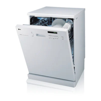
3. PARTS NAME 1. Control Panel 10. Adjust Leg 2. Door Handle 11. Upper Rack 3. Front Cover 12. Cutlery Basket 4. Lower Cover 13. Detergent & Rinse Aid Dispenser 5. Process Monitor 14. Vapor Vent Cover 6. Power Switch 15. -
Page 7: Features & Technical Explanation
4. FEATURES & TECHNICAL EXPLANATION 4-1 New Technology Introduction 4-1-1. High Temperature Rinsing (Extra Hot function) • During the high temp. Rinse course, water temperature in an dishwasher reaches 80°C, considerably higher than the average rinse temperature in conventional dishwashers(65°C). This is how Rinse 80°C can eliminate some bacteria such as salmonella. -
Page 8: Half Load
4-2 Display Panel HALF LOAD • In case of small load, use upper or lower rack only to save energy. • With each press, can select upper or lower rack only. • In case you don’t select this button, the machine always works vario washing, which operate upper and lower spray arm alternately. -
Page 9: Delay Start
INDICATOR TIME LEFT DELAY START • Before starting, the display window shows the running time of • Refill with • If you want to delay the the selected program. rinse aid start of selected program, • After starting, the display window shows the remaining time. press this button before •... -
Page 10: Buzz On/Off
4.3 TEST MODE CHECK PROGRAM(START IN THE STATE OF THE CLOSED DOOR) The number of BUTTON DISPLAY Load and Checking points pushing button Quick + Pre-wash 1 TIME n : 0H All LEDs are lighting + POWER S/W 1 TIME 2 : 22 All LEDs are lighting (Half Load) KEY... -
Page 11: Wiring Diagram
5. WIRING DIAGRAM - 11 -... -
Page 12: Program Chart(Schematic Diagram)
6. PROGRAM CHART(SCHEMATIC DIAGRAM) - 12 -... -
Page 13: How To Disassemble
7. HOW TO DISASSEMBLE BEFORE DISASSEMBLING THE DISHWASHER ; 1) Remove the plug from electric outlet to avoid electric shock. 2) Close the Water Tap(faucet). 3) Remove all dishes and items in the dishwasher. 4) Remove the Lower Rack and the Upper Rack. 5) In case of the water softner assembly model, open the water softner cap to flow out the water to sump and drain to avoid the floor wet. -
Page 14: Door Assembly
4. Balance weight 1) Remove side 4 screws. 2) Lift the balance weight. 5. Door Assembly 1) Front Cover ① Open the door. ② Remove 6 screws(stainless). ③ Close the door slowly and remove front cover downwards. 2) Control Panel Assembly Main Display Part ①... - Page 15 3) Fan ① Open the door. ② Remove the air duct. Cover ③ Remove the wire connections. Detergent Inner ④ Remove the outer cover by removing 1 Dispenser Cover screw. ⑤ Remove 2 fixing screws inside and turn the Inner Cover counterclockwise. Door Liner 4) Detergent Dispenser ①...
-
Page 16: Tub Assembly
6. Base spacer ① Remove 4 screws. ② Lift the front side of dishwasher and pull the base spacer forward. 7. Tub assembly 1) Nozzle ① Pull up the nozzle. 2) Filter Assembly Inner filter ① Turn inner filter counterclockwise and lift inner filter and middle filter. - Page 17 4) Tub ① Turn the air guide nut counter-clockwise. (Special tool might be needed.) Be careful the rubber packing of air guide assembly should not be lost. ② Remove 4 screws for sump holder . ③ Remove side 8 screws. ④...
- Page 18 10. C-Base Assembly 1) synchronous motor ① Remove the 2 screws. ② Lift the cam upward. ※ Be careful not to install upside down. (part number on the cam should face the motor.) 2) Vario valve ① Remove 4 screws and lift the cover upward.
- Page 19 5) Aquastop(Not on all models) ② ① Press the holder hook as shown in figure. ② Pull the hose assembly. ① ① 6) Drain Hose ③ ① Press the rear side hook. ② Pull the holder forward. ② ③ Pull the holder upward. - 19 -...
- Page 20 7-2. DISASSEMBLE C-BASE ASSEMBLY Be careful not to be injured by the sharp edge of tub. 1. Top Plate �See 7-1. 1. (Page 17) 2. Low Cover �See 7-1. 2. (Page 17) 3. Cabinet-R/L �See 7-1. 3. (Page 17) 4. Air Guide ①...
- Page 21 6. Remove the side screws 1) Remove side 8 screws. 2) Remove 2 Earth screws of right side. 3) Remove 1 motor bracket screw. 4) Lift base upward slightly. (You can’t lift up base perfectly because of some parts connecting to base.) 7.
- Page 22 4) Disconnect wire from the inlet valve or Aquastop ※ Now, you can remove the base from the tub perfectly. 8. C-Base Assembly ※ You can repair the parts in the C-Base like heater case, washing pump, drain motor etc. you may refer to 7-1. 10. 2)~10) (Page 21~25) ※...
-
Page 23: Trouble Shooting Methods
8.TROUBLE SHOOTING METHODS A. TROUBLE SHOOTING ACCORDING TO DISPLAYED ERROR MESSAGE POSSIBLE CAUSE ERROR MESSAGE REMEDY FOR ERROR OCCURRENCE �The Water Tap is not opened. �Open the Water Tap. INLET ERROR �The Inlet Hose is kinked. �Repair the Inlet Hose. �a) Close the Water Tap. -
Page 24: Error Message
POSSIBLE CAUSE ERROR MESSAGE REMEDY FOR ERROR OCCURRENCE EXCESS ERROR �The Inlet Valve is troubled. �Replace the Inlet Valve. displayed �Replace the air breaker. �The Air Break is troubled. Condition �The Sensor Assembly is troubled. �Replace the sensor assembly. Excessive water is sup- �The Controller is troubled. -
Page 25: Trouble Diagnoses And Repair By Symptom
B. TROUBLE DIAGNOSES AND REPAIR BY SYMPTOM No Power on when the power button pressed. • Insert the Plug Correctly. The plug is correctly inserted in the • Check the electricity is failed or not. Socket-Outlet? The Fuse or • Replace the Fuse or Circuit Breaker of house. Circuit Breaker of house is O.K? The Thermal Fuse... - Page 26 The Wash Pump/Motor does not run. • Close the Door Tightly. The Door is tightly • Check the Door Switch in Latch Handle. closed? The Pump/Motor is • Remove the cause of block or replace the Pump/Motor. not blocked? The circuit of Pump/ •...
- Page 27 Washing Results are not Satisfactory After washing, are there still ㆍ Reduce the amount of Rinse-Aid White deposits or streaks on (for Streak) the dishes? ㆍ Does salt refill lamp blink? (Refill salt) After washing, are there still food soils on the dishes? Check that : - the amount of detergent Correctly used or not - Filters clogged or not.
- Page 28 Power Button not automatically off after operation. Check the button is blocked by foreign materials. Check the Power Switch.(Replace it, if necessary.) Check the Controller.(Replace it, if necessary.) - 28 -...
-
Page 29: Installation Instruction
9. INSTALLATION INSTRUCTION Step1: Prepare Cupboard opening 1. This dishwasher is designed to fit to the size shown as below. 2. Select a location as close to sink as possible for easy connections to water and drain lines. 3. The dishwasher should not be installed more than 3 meters from sink for proper drainage. 4. - Page 30 Step 2 : PREPARE ELECTRICAL WIRING CAUTION For personal safety, remove house fuse or open circuit breaker before installation. Do not use an extension cord or adapter plug with this appliance. Electrical and grounding connections must comply with the national electrical code/provincial and municipal code and/or other local codes.
- Page 31 Step 5 : DRAIN LINE CONNECTION 1. If the end drain hose does not fit to the drain line, use a piece of rubber connector (not supplied) that must be resistant to heat and detergent and may be obtained from a plumbing shop. 2.
- Page 32 Drain Hose Extension ■ Drain Hose extension kits are available from through your local service centre. Extend drain Hose as shown below. 200 mm Max. Sink Copper pipe fl 20mm flared at drain nose and other end if required. Use the couplings for connections when you extend drain hose.
-
Page 33: Exploded View
10. EXPLODED VIEW - 33 -... -
Page 34: Exploded View
EXPLODED VIEW A001 A002 F008 A020 A010 A050 A149 A147 A090 A080 A156 A144 A146 A155 A110 A145 A142 A150 A070 A140 A060 - 33 -... - Page 35 EXPLODED VIEW - TUB ASSEMBLY F040 F060 F050 F011 F013 F022 F110 F171 F113 E001 F117 F008 F111 F112 F143 F004 F144 F011 F191 F132 F183 F182 F181 F210 F013 F113 F117 F111 F118 - 36 -...
- Page 36 PANEL ASSEMBLY / DOOR ASSEMBLY K252 K262 K260 K200 K251 K216 K203 K201 K209 K212 K010 K002 K122 K123 K001 F142 K101 F141 K003 K124 K110 K121 F174 - 37 -...
- Page 37 EXPLODED VIEW - BASE ASSEMBLY M230 A131 A130 A276 M250 M023 A030 M280 M270 A040 M260 - 38 -...
- Page 38 EXPLODED VIEW - SUMP ASSEMBLY M001 M072 M073 M070 M071 M074 A120 M005 M006 M024 M026 M028 M090 M025 M031 M080 M083 M086 M027 M051 M029 M008 M018 M061 M060 M002 M062 - 39 -...
- Page 39 P/No. : 3828DD3007H...
Need help?
Do you have a question about the LD-1415M1 and is the answer not in the manual?
Questions and answers