Table of Contents
Advertisement
Owner's Manual & Safety Instructions
Save This Manual
inspection, maintenance and cleaning procedures. Write the product's serial number in the back of the manual
near the assembly diagram (or month and year of purchase if product has no number). Keep this manual and
the receipt in a safe and dry place for future reference.
Using an engine indoors
CAN KILL YOU IN MINUTES.
Engine exhaust contains carbon monoxide.
This is a poison you cannot see or smell.
NEVER use inside
a home or garage,
EVEN IF doors and
windows are open.
Visit our website at: http://www.harborfreight.com
Email our technical support at: tech@harborfreight.com
REV 11k
When unpacking, make sure that the product is intact
and undamaged. If any parts are missing or broken,
please call 1-800-520-0882 as soon as possible.
©
Copyright
2010 by Harbor Freight Tools
No portion of this manual or any artwork contained herein may be reproduced in
any shape or form without the express written consent of Harbor Freight Tools.
Diagrams within this manual may not be drawn proportionally. Due to continuing
improvements, actual product may differ slightly from the product described herein.
Tools required for assembly and service may not be included.
Keep this manual for the safety warnings and precautions, assembly, operating,
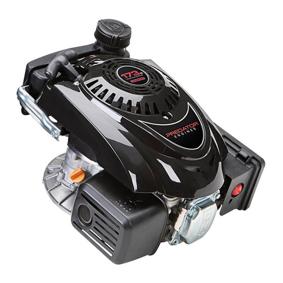
Vertical Engine
Only use OUTSIDE
and far away from
windows, doors,
and vents.
®
. All rights reserved.
173cc
Read this material before using this product.
Failure to do so can result in serious injury.
SAVE THIS MANUAL.
ITEM 68122 68123
Advertisement
Table of Contents

Related Manuals for Predator Engines 173cc


Summary of Contents for Predator Engines 173cc
- Page 1 No portion of this manual or any artwork contained herein may be reproduced in Failure to do so can result in serious injury. any shape or form without the express written consent of Harbor Freight Tools. Diagrams within this manual may not be drawn proportionally. Due to continuing SAVE THIS MANUAL.
-
Page 2: Table Of Contents
Run Time @ 50% Load 40 minutes with full tank Sound Level 104 dB Bore x Stroke 70 mm x 45 mm Displacement 173cc Compression Ratio 8.5:1 Rotation viewed from PTO Counterclockwise (power takeoff - the output shaft) Shaft dia. -
Page 3: Safety
WARNING SYMBOLS AND DEFINITIONS This is the safety alert symbol. It is used to alert you to potential personal injury hazards. Obey all safety messages that follow this symbol to avoid possible injury or death. Indicates a hazardous situation which, if not avoided, will result in death or serious injury. - Page 4 Set up Precautions 1. Gasoline fuel and fumes are flammable, and 4. Set up and use only on a flat, level, potentially explosive. Use proper fuel storage well-ventilated surface. and handling procedures. Do not store fuel 5. Wear ANSI-approved safety goggles, heavy-duty or other flammable materials nearby.
- Page 5 25. This product contains or, when used, produces a 14. Use only accessories that are recommended chemical known to the State of California to cause by Harbor Freight Tools for your model. cancer and birth defects or other reproductive harm. Accessories that may be suitable for one (California Health &...
- Page 6 Service Precautions 1. Before service, maintenance, or cleaning: 6. Have the equipment serviced by a qualified repair person using only identical replacement parts. a. Release the brake handle, stopping the engine. This will ensure that the safety of the equipment b.
- Page 7 Engine Components Fuel Cap Priming Bulb Starter Handle Dipstick Muffler Filter Brake Throttle Serial Number Location (Write on front cover of manual.) Vertical Engine For technical questions, please call 1-800-520-0882. Page 7...
-
Page 8: Set Up
Set Up Read the ENTIRE IMPORTANT SAFETY INFORMATION section at the beginning of this manual including all text under subheadings therein before set up or use of this product. TO PREVENT SERIOUS INJURY: Operate only with proper spark arrestor installed. Operation of this equipment may create sparks that can start fires around dry vegetation. -
Page 9: Operation
Operation Read the ENTIRE IMPORTANT SAFETY INFORMATION section at the beginning of this manual including all text under subheadings therein before set up or use of this product. Pre-Start Checks Inspect engine and equipment looking for damaged, loose, and missing parts before set up and starting. -
Page 10: Starting The Engine
Starting the Engine Before Starting the Engine: a. Follow the Set Up Instructions in the equipment manual to prepare the equipment. b. Inspect the equipment and engine. c. Fill the engine with the proper amount and type of both fuel and oil. d. -
Page 11: Stopping The Engine
4. Grip the Starter Handle of the Engine loosely and pull it gently until resistance is felt. Allow Cable to retract fully and then pull it quickly. Repeat until the engine starts. Note: Do not let the Starter Handle snap back against the engine. -
Page 12: Maintenance
Maintenance WARNING TO PREVENT SERIOUS INJURY FROM ACCIDENTAL STARTING: Release the brake handle, wait for the engine to cool, and disconnect the spark plug cap before performing any inspection, maintenance, or cleaning procedures. TO PREVENT SERIOUS INJURY FROM EQUIPMENT FAILURE: Do not use damaged equipment. -
Page 13: Engine Oil Change
Checking and Filling Fuel WARNING! TO PREVENT SERIOUS INJURY FROM FIRE: Fill the fuel tank in a well-ventilated area away from ignition sources. If the engine is hot from use, shut the engine off and wait for it to cool before adding fuel. Do not smoke. - Page 14 3. Inspect the spark plug: 5. Install the new spark plug or the cleaned spark plug If the electrode is oily, clean it using a clean, dry into the engine. Gasket-style: Finger-tighten until the rag. If the electrode has deposits on it, polish it gasket contacts the cylinder head, then about 1/2-2/3 using emery paper.
-
Page 15: Troubleshooting
Troubleshooting Problem Possible Causes Probable Solutions Engine will not start MOWER ENGINE SPECIFIC: MOWER ENGINE SPECIFIC: 1. Brake Handle not held or brake 1. Make sure brake handle is held down cable not connected properly. and brake cable is properly adjusted. 2. -
Page 16: Probable Solutions
Problem Possible Causes Probable Solutions Engine stops 1. Low oil shutdown. 1. Fill engine oil to proper level. suddenly Check engine oil before EVERY use. 2. Fuel tank empty or full of impure 2. Fill fuel tank with fresh 87+ or low quality gasoline. -
Page 17: Warranties
The United States Environmental Protection Agency (herein EPA) The California Air Resources Board (herein CARB), the United and Harbor Freight Tools (herein HFT) are pleased to explain the States Environmental Protection Agency (herein EPA), and Harbor emission control system warranty on your 1997 and later Small Off- Freight Tools (herein HFT) are pleased to explain the emission control Road Engine (herein engine). - Page 18 HFT. the engine, for any alternative usage, for any damage to goods, loss of time, or inconvenience. Warranty coverage shall also be Harbor Freight Tools Emission Control excluded for any part which fails, malfunctions, or is damaged Defects Warranty Coverage due to failure to follow the maintenance and operating instructions set forth in the Owner’s Manual including, but not limited to:...
-
Page 19: Parts Lists And Diagrams
Parts Lists and Diagrams Mounting Hole Diagram Note: Not to scale. 1.1 in. / 28mm 0.98 in. / 25mm 6*Ø0.35 in. / 9mm Ø0.24 in. / 6mm Ø8 in. / 203mm Ø0.34 in. / 8.7mm Ø1 in. / 25.4mm Ø0.24 in. / 6mm Ø0.34 in. - Page 20 68122 Parts List Part Description Qty. Part Description Qty. Cover, Cylinder Head Plate Asm., Lifter Stopper Gasket, Cylinder Head Cover Lifter, Valve Head Asm., Cylinder Tappet, Valve Gasket, Cylinder Head Camshaft Asm. Bolt Valve, Exhaust Plug, Spark Starter Asm., Recoil Bolt, Cylinder Head Housing, Engine Bracket, Muffler Shield...
- Page 21 68122 Assembly Diagram 10 5 10 6 10 9 10 7 10 8 10 0 10 1 10 2 10 1 10 4 10 3 2930 12 0 72 73 81 81 Vertical Engine For technical questions, please call 1-800-520-0882. Page 21...
- Page 22 68123 Parts List Part Description Qty. Part Description Qty. Cover, Cylinder Head Spring, Valve Gasket, Cylinder Head Cover Guide, Seal Head Asm., Cylinder Bolt, Valve Adjusting Gasket, Cylinder Head Valve, Intake Bolt Plate Asm., Lifter Stopper Plug, Spark Lifter, Valve Bolt, Cylinder Head Tappet, Valve Bracket, Muffler Shield...
- Page 23 68123 Assembly Diagram 10 0 89 90 29 30 10 1 10 5 10 2 10 7 10 6 10 9 10 8 10 4 10 3 70 71 79 79 Vertical Engine For technical questions, please call 1-800-520-0882. Page 23...
- Page 24 3491 Mission Oaks Blvd. • PO Box 6009 • Camarillo, CA 93011 • (800) 520-0882 www.harborfreight.com...