Table of Contents
Advertisement
Advertisement
Table of Contents

Related Manuals for MSI MS-7204


Summary of Contents for MSI MS-7204
- Page 1 945P Series MS-7204 (v1.X mBTX Mainboard)
-
Page 2: Fcc-B Radio Frequency Interference Statement
VOIR LA NOTICE D’INSTALLATION AVANT DE RACCORDER AU RESEAU. Micro-Star International MS-7204 This device complies with Part 15 of the FCC Rules. Operation is subject to the following two conditions: (1) this device may not cause harmful interference, and... -
Page 3: Copyright Notice
Alternatively, please try the following help resources for further guidance. † Visit the MSI homepage & FAQ site for technical guide, BIOS updates, driver updates, and other information: http://www.msi.com.tw & http://www.msi. -
Page 4: Safety Instructions
Safety Instructions Always read the safety instructions carefully. Keep this User’s Manual for future reference. Keep this equipment away from humidity. Lay this equipment on a reliable flat surface before setting it up. The openings on the enclosure are for air convection hence protects the equip- ment from overheating. -
Page 5: Weee Statement
WEEE Statement... -
Page 8: Table Of Contents
CONTENTS FCC-B Radio Frequency Interference Statement ............ii Copyright Notice ......................iii Technical Support ......................iii Revision History ......................iii Safety Instructions ......................iv WEEE Statement ......................v Chapter 1. Getting Started ..................1-1 Mainboard Specifications ................... 1-2 Mainboard Layout ....................1-4 Packing Contents .................... - Page 9 Serial ATA Connectors controlled by Intel ICH7: SATA1~SATA4 ... 2-16 Video-In Connector: JVID1 ............... 2-17 Front Line-In Connector: JL_IN1.............2-17 SCART Output Connector: JSCA1............2-17 Front LCD Moduke Header: JFLCD............2-18 Front Panel Connectors: JF_P1 ..............2-18 Front USB Connectors: JUSB1 / JUSB2 ..........2-19 Front Panel Audio Connector: JAUD1 ............
-
Page 10: Chapter 1. Getting Started
Getting Started Chap t er 1 . Ge tting Started Getting Started Thank you for choosing the 945P Series (MS-7204) v1.x mBTX mainboard. The 945P Series mainboard is based on Intel ® 945P and Intel ICH7/ICH7R chipset for optimal system efficiency. -
Page 11: Mainboard Specifications
M S-7204 mBTX M ainboard Mainboard Specifications Supports Intel Pentium 4/ Celeron D Prescott LGA775 processors (Prescott † ® and Smithfield) in LGA775 package. Supports 2005 Performance FMB CPU VR Design. † Supports 3/4 pin CPU Fan Pin-Header with Fan Speed Control. †... - Page 12 Getting Started - 1 coaxial SPDIF-Out / SPDIF-In / Optical SPDIF-Out / SPDIF-In - 8 USB ports (Rear * 4/ Front * 4) - 1 RJ-45 LAN jack Intel 8100C † - Supports 10 / 100 Mb/s. 1394(optional) Supports two IEEE1394 onboard pinheader. Transfer rate is up to 400 Mbps. †...
-
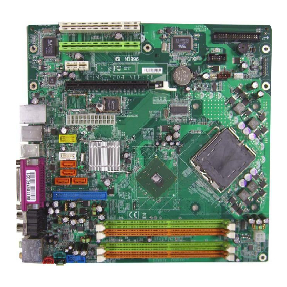
Page 13: Mainboard Layout
D I M M 1 D I M M 2 T:SPDIF-Ou t B:OPT -Out ALC882 Front-Out SS-Out D I M M 3 L ine-In D I M M 4 CS-Out JPWR1 JSCA1 BS-Out JVID1 JAUD1 JL_IN1 945P Series(MS-7204) v1.x mBTX Mainboard... -
Page 14: Chapter 2. Hardware Setup
Hardware Setup Chapter 2. Hardware Setup Hardware Setup This chapter tells you how to install the CPU, memory modules, and expansion cards, as well as how to setup the jumpers on the mainboard. Also, it provides the instructions on connecting the periph- eral devices, such as the mouse, keyboard, etc. -
Page 15: Quick Components Guide
M S-7204 mBTX M ainboard Quick Components Guide JLPC1, p.2-15 FDD1, p.2-14 PCI Slots 1~2, JFW1, p.2-23 p.2-20 JFLCD, p.2-18 JF_P1, PCI-E Slots, p.2-18 p.2-22 C PU F A N1 , SYS_FAN1, p.2-14 BTX1, p.2-9 JBAT1, p.2-21 JUSB1/2, p.2-19 CPU, Back Panel p.2-3 I/O, p.2-10... -
Page 16: Central Processing Unit: Cpu
If you do not have the CPU cooler, contact your dealer to purchase and install them before turning on the computer. For the latest information about CPU, please visit http://www.msi.com.tw/ program/products/mainboard/mbd/pro_mbd_cpu_support.php. MSI Reminds You... -
Page 17: Cpu & Cooler Installation
CPU Clip to clip the CPU up, pressing the clips on both sides to the center, as the arrows shown. MSI Reminds You... 1. Confirm if your CPU cooler is firmly installed before turning on your system. - Page 18 Hardware Setup 5. The CPU has a plastic cap on it to 6. Remove the cap from lever hinge side protect the contact from damage. (as the arrow shows). The pins of Before you have installed the CPU, socket reveal. always cover it to protect the socket pin.
- Page 19 Holes on mainboard Holes on case The fan of the cooler. MSI Reminds You... 1. Check the information in PC Health Status of H/W M onitor in BIOS (Chapter 3) for the CPU temperature. 2. Whenever CPU is not installed, always protect your CPU socket pin with the plastic cap covered (shown in Figure 1) to avoid damaging.
-
Page 20: Memory
DDR2 memory module in the DDR2 slot (DIMM1~DIMM4). Otherwise, you are not able to boot up your system and your mainboard might be damaged. For the updated supporting memory modules, please visit http://www.msi. com.tw/program/products/mainboard/mbd/pro_mbd_trp_list.php. DIMM1~DIMM4 (from Top to buttom Channel A (DIMM1 &... -
Page 21: Installing Ddr2 Modules
256MB~1GB 256MB~1GB 256MB~1GB 1GB~4GB MSI Reminds You... - Dual-channel DDR works ONLY in the 5 combinations listed in the table shown in the previous page. - Please select the identical memory modules to install on the dual channel, and DO NOT install three memory modules on three DIMMs, or it may cause some failure. -
Page 22: Power Supply
Pin Definition SIGNAL JPW1 MSI Reminds You... 1. These two connectors connect to the BTX power supply and have to work together to ensure stable operation of the mainboard. 2. Power supply of 350 watts (and above) is highly recommended for system stability. -
Page 23: Back Panel
M S-7204 mBTX M ainboard Back Panel The back panel provides the following connectors: SPDIF- SPDIF- Front-Out Parallel 1394 M ou se Keyboard COM Port Opt- Opt- USB Ports CB-Out SS-Out Line-In BS-Out Mouse/Keyboard Connector The mainboard provides a standard PS/2 mouse/keyboard mini DIN connector ®... -
Page 24: Serial Port Connector: Com Port
Hardware Setup Serial Port Connector: COM Port The mainboard offers one 9-pin male DIN connector COM Port. It’s a 16550A high speed communication port that send/receive/ 16 bytes FIFOs. You can attach a serial mouse or other serial device directly to it. 1 2 3 4 5 6 7 8 9 9-Pin Male DIN Connector... -
Page 25: Lan (Rj-45) Jack
M S-7204 mBTX M ainboard LAN (RJ-45) Jack The mainboard provides 1 standard RJ-45 jack for connection to single Local Area Network (LAN). This LAN enables data to be transferred at 100Mbps or 10Mbps. You can connect a network cable to it. 10/100 LAN Pin Definition SIGNAL DESCRIPTION... -
Page 26: Parallel Port Connector: Lpt1
Hardware Setup Parallel Port Connector: LPT1 The mainboard provides a 25-pin female centronic connector as LPT. A parallel port is a standard printer port that supports Enhanced Parallel Port (EPP) and Ex- tended Capabilities Parallel Port (ECP) mode. Pin Definition SIGNAL DESCRIPTION STROBE... -
Page 27: Connectors
Control Sensor CPUFAN1 SYS_FAN1 MSI Reminds You... 1. Always consult the vendors for proper CPU cooling fan. 2. CPUFAN1 supports the fan control. Fan/heatsink with 3 or 4 fins are both available. 3. Be sure to configure the CPU FAN PIN Select in BIOS for the CPU Fan you are using first. -
Page 28: Hard Disk Connector: Ide1
Intel ICH7R, which supports PIO & Bus Master operation modes and it can connect up to two Ultra ATA drives. IDE1 (blue) MSI Reminds You... If you install two hard disks on cable, you must configure the second drive to Slave mode by setting its jumper. Refer to the hard disk documentation supplied by hard disk vendors for jumper setting instructions. -
Page 29: Serial Ata Connectors Controlled By Intel Ich7: Sata1~Sata4
Take out the dust cover and connect to the hard disk devices Connect to serial ATA ports MSI Reminds You... Please do not fold the serial ATA cable in a 90-degree angle, since this might cause the loss of data during the transmission. 2-16... -
Page 30: Video-In Connector: Jvid1
Hardware Setup Video-In Connector: JVID1 The connector is for TV-Tuner card audio connector. JVID1 Front Line-In Connector: JL_IN1 The connector is for front line-in connector. JL_IN1 SCART Output Connector: JSCA1 The JSCA1 connector allows you to connect the output device with SCART spec. -
Page 31: Front Lcd Moduke Header: Jflcd
M S-7204 mBTX M ainboard Front LCD Module Header: JFLCD The connector allows you to connect to Medion VFD LCD panel. +5VSB Front Panel Connectors: JF_P1 The mainboard provides one front panel connector for electrical connection to the front panel switches and LEDs. JF_P1 is compliant with Intel Front Panel I/O ®... -
Page 32: Front Usb Connectors: Jusb1 / Jusb2
USB1+ JUSB1 / JUSB2 (USB 2.0/standard spec) USBOC MSI Reminds You... Note that the pins of VCC and GND must be connected correctly, or it may cause some damage. Front Panel Audio Connector: JAUD1 The F_AUDIO front panel audio connector allows you to connect to the front panel audio and is compliant with Intel Front Panel I/O Connectivity Design Guide. -
Page 33: Ieee 1394 Connector: Jfw1 (Optional)
M S-7204 mBTX M ainboard IEEE 1394 Connector: JFW1 (Optional) The mainboard provides one 1394 pin header that allow you to connect optional IEEE 1394 port. Pin Definition SIGNAL SIGNAL TPA+ TPA- Ground Ground TPB+ TPB- JFW1 Cable power Cable power Key (no pin) Ground 2-20... -
Page 34: Jumpers
JBAT1 Keep Data Clear Data MSI Reminds You... You can clear CMOS by shorting 2-3 pin while the system is off. Then return to 1-2 pin position. Avoid clearing the CMOS while the system is on; it will damage the mainboard. -
Page 35: Slots
M S-7204 mBTX M ainboard Slots The mainboard provides a PCI Express x16 slot, a PCI Express x1 slot and three 32-bit PCI bus slots. PCI Express Slots (optional) The PCI Express slots, as a high-bandwidth, low pin count, serial, intercon- nect technology, support Intel highest performance desktop platforms utilizing the Intel Pentium 4 processor with HT Technology. -
Page 36: Pci (Peripheral Component Interconnect) Slots
Hardware Setup PCI (Peripheral Component Interconnect) Slots The PCI slots allow you to insert the expansion cards to meet your needs. W hen adding or removing expansion cards, make sure that you unplug the power supply first. Meanwhile, read the documentation for the expansion card to make any necessary hardware or software settings for the expansion card, such as jumpers, switches or BIOS configuration.