Table of Contents
Advertisement
Quick Links
Advertisement
Table of Contents

Subscribe to Our Youtube Channel
Related Manuals for Perreaux éloquence 150i


Summary of Contents for Perreaux éloquence 150i
- Page 1 éloquence 150i Integrated Amplifier Owners Manual PERREAUX...
- Page 3 éloquence 150i Integrated Amplifier Designed and Manufactured in Dunedin, New Zealand...
-
Page 4: Important Safety Instructions
Explanation of symbols used in this manual or on the rear of the device: Mains Plugs • This device is supplied with a non-rewireable mains plug for the This symbol is intended to alert the user to the presence intended country. of uninsulated dangerous voltages within the enclosure of • Replacement mains leads can be obtained from your Perreaux dealer. sufficient magnitude to cause electric shock. Should you need to change the plug please dispose of it carefully. A plug with bared conductors is dangerous if engaged in a live This symbol is intended to alert the user to the presence of socket. important operation, maintenance and servicing information •... -
Page 5: General Safety Instructions
Follow all instructions. • The power cord should be routed so that it is not likely to be walked on • Do not use the device near water, for example near a bathtub, kitchen or pinched by items placed on or against it. sink, in a wet basement, near a swimming pool, etc. • Unplug the device during lightning storms or when unused for long • Clean only with a dry cloth. periods of time. • Mounting to a wall or ceiling should be via a heavy-duty bracket or • DO NOT let objects or liquids fall into the device, expose the device to drip- shelf designed for audio equipment use. ping or splashing or place a vessel containing liquid on top of the device. • The device should be situated away from heat sources such as radiators, • Keep this device out of reach of children. stoves, or other appliances that produce excessive amounts of heat. • DO NOT operate the device with the cover removed. • DO NOT place the device directly onto carpeted surfaces. • DO NOT bypass any fuse, replace only with the value and type specified. • Avoid exposing the device to extremely high or low temperatures. • DO NOT attempt to repair the device. In the event of a problem, please • The device should be connected to a mains power supply only of the contact your Perreaux dealer. type described in the operating instructions, and/or as marked on the • DO NOT operate this product in an explosive atmosphere. rear of the unit. -
Page 6: Table Of Contents
TECHNICAL SPECIFICATIONS ................. PHYSICAL DIMENSIONS ..................Copyright and Acknowledgments éloquence 150i Manual Version 1.0 Copyright © 2009 Perreaux Industries Ltd. change without notice, and should not be construed as a commitment by Perreaux Industries Ltd. Perreaux Industries Ltd., Gladstone Road, Mosgiel, Dunedin 9024, New Zealand. Perreaux Industries Ltd. assumes no responsibility or liability for any errors or inaccuracies that may appear in this manual. All rights reserved. No part of this publication may be reproduced, stored in a retrieval system, or transmitted, in any form or by any means, electronic, mechanical, photocopying, recording, or otherwise, without the prior All trademarks and registered trademarks are the property of their respective owners. Perreaux, the Perreaux written permission of the publisher. The content of this manual is furnished for information use only, is subject to logo and éloquence are trademarks of Perreaux Industries Ltd. All rights reserved. Printed in New Zealand. -
Page 7: Introduction
Endeavour to understand every detail by familiarising yourself with the • MOSFET technology controls and features as you read. You will find it easier to install using the relevant sections of this manual as a reference. • Balanced input • Intuitive user interface We have attempted to explain every feature and operation facet clearly and • Highly customisable concisely. Your Perreaux dealer will be happy to assist if you encounter any • Infrared remote control unforeseen problems. • Smart home integration Read this manual, install your unit correctly and realise the sonic signifi- • Protection cance of your investment in Perreaux. • Construction Perreaux products are designed to provide the utmost in sonic realism and •... -
Page 8: Features
Features Highly Refined Circuit Design Balanced Input All Perreaux analogue amplification stages are based on circuits that have The éloquence 150i features a balanced input via XLR connectors, allow- been extensively optimised over many years of continuous development. ing optimal performance with the many high-end CD players and other By starting with excellent circuit designs and working with them over the audio components that utilise the benefits of balanced outputs. years, we are able to discover the many small refinements that add up to Intuitive User Interface superlative performance, in a variety of applications. The interface knob on the front panel of the éloquence 150i is the heart Capacitor-Free Signal Path of the user interface experience – allowing fundamental control of the The inputs of the éloquence 150i are DC coupled and there is not a volume, and intuitive navigation and adjustment within the éloquence single capacitor in the signal path that the audio signal passes through, menu system. -
Page 9: Optional Modules
Construction Regardless of the technology used, numerous details must be executed to fully realise the potential of a Perreaux design. The quality of individual components, the care and craftsmanship with which they are assembled and the exhaustive inspection and testing we employ help raise the value of Perreaux products. In addition to yielding the best performance, careful attention to details is the secret to achieving both reliability and longevity. -
Page 10: Installation
Installation Unpacking Other Devices The éloquence 150i is supplied with the following accessories: Ideally, your éloquence 150i integrated amplifier should not be located directly above or adjacent to other heat-producing products such as radia- • Remote control tors, other power amplifiers, etc. If multiple amplifiers are being used and • Mains lead space is restricted, placing them side by side is preferable to stacking. • This manual It is advisable to position your éloquence 150i away from (and if possible, We recommend you retain the packaging for reuse in case you need to connected to a power socket on a different circuit from) powerful electrical transport the unit at a later date. or electronic products such as TV sets, computers, cookers, fridges etc. Placement This will prevent the possibility of the strong electrical and electromagnetic emissions or interference given off by such devices adversely affecting the Your éloquence 150i integrated amplifier should generally be placed close to your primary source component, keeping interconnect cabling short. performance of your amplifier. Position all other components of your system close enough to your 150i to avoid having to stretch or extend any of the interconnect cables. Ventilation Requirements Your éloquence 150i requires dissipating considerable power in the form of heat. It should be placed in a position that does not restrict the airflow around it. -
Page 11: Quick Start
Quick Start If you are like us, the first thing you will want to do is to play your favourite Play your source material piece of music through your new éloquence 150i integrated amplifier. The Start playing your favourite recording. following instructions are written to enable you to achieve this as quickly Increase the volume as possible. These are not comprehensive instructions, but are designed Slowly increase the volume on your éloquence 150i to achieve a comfort- to enable you to play music now! able listening level. Please take the time to read this manual thoroughly, as the éloquence Congratulations! 150i incorporates many features which enhance its operation. Now that you have achieved your first objective, sit back, relax and please Turn off associated components read the rest of the manual at your own pace, in your favourite armchair, This minimises the potential to damage your éloquence 150i, or any other whilst enjoying a glass of wine. You’ll find the whole experience much components, when connecting the device into your system. -
Page 12: Connecting
Connecting - Rear panel Important: Please refer to the owner’s manual of your balanced output source to verify that the pin assignments of the output connectors correspond to the Before making any connections, switch off the mains power to all compo- éloquence 150i. If this is not the case, wire the cables so that the appropri- nents in your system. ate output pin connects to the equivalent input pin. 1 Balanced Input 2 Amp In The balanced (XLR) inputs accept signals from a source component with The unbalanced (RCA) amp in inputs allow direct connection to the power balanced outputs. amplifier sections of your éloquence 150i when used in conjunction with the The pin assignments of the XLR input connectors are: Separate function (see Separate, page 22). Pin 1: Signal ground 3 Pre Out Pin 2: Signal + (non-inverting) The unbalanced (RCA) preamp outputs provide a single-ended preamp Pin 3: Signal – (inverting) level audio signal for connection to an external power amplifier or active Shield ground: Chassis ground... -
Page 13: Tape Out
4 Tape Out Link™ IR receiver) allows the amplifier to be placed inside a cabinet or outside the normal line-of-sight of the remote control. The plug must meet The unbalanced (RCA) tape outputs provide a single-ended line level audio the specifications shown below: signal, suitable for recording from the selected source input. This output is disconnected when INPUT 5 is selected; to prevent any potentially damag- Sleeve Ring Sleeve: +12VDC ing feedback loops if the tape output is connected to this input. Ring: GND Tip: Signal 5 Trigger Output The trigger output allows your éloquence 150i to control the standby state of a remotely connected device. The remote trigger output accepts a mono 3.5mm (8”) plug. The trigger output voltage is 12V DC when the amplifier is not in standby and is 0V DC when in stadby. Note: Do not use a mono 3.5mm (8”) plug, this may cause damage to the IR input. The trigger output plug must meet the specifications shown below: 7 IR Output Sleeve The IR (infrared) output allows your éloquence 150i to relay un-modulated commands received via the IR sensor on the front panel, or to pass on Sleeve: GND commands from home automation systems or other components received Tip: Signal via the IR input. -
Page 14: Analogue Inputs
9 Analogue Inputs 12 Ground Terminal The unbalanced (RCA) analogue inputs accept signals from source compo- The ground terminal on your éloquence 150i is most often used for the nents with single-ended outputs. ground wire of a turntable, if you have the optional phono preamplifier installed. Connecting the ground wire from your turntables tonearm to this Input 1 / phono terminal usually minimises any hum or buzzing to which the turntable may otherwise be susceptible. Your authorised Perreaux dealer can assist you If you have a turntable you would like to use with the system, an optional in handling this problem if it should arise. phono module is available from your Perreaux dealer. Once installed in your éloquence 150i, the Input 1 connectors become your phono inputs, and the phono options in the menu system become active. Input 4 / Theatre Input 4 is set as a home theatre loop (HT LOOP) straight from the factory and bypasses the volume control. Please ensure the volume level of the connected processor or receiver is suitably attenuated before selecting this input. -
Page 15: Operation
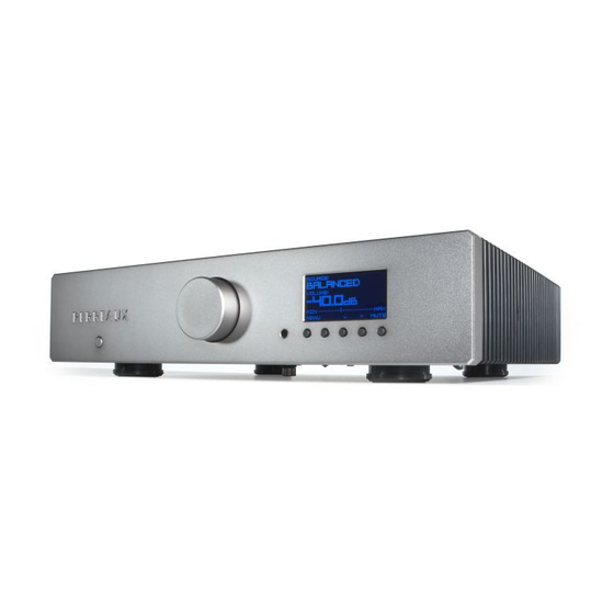
Operation - Front Panel 1 Power Button 3 Infrared Sensor The power button connects and disconnects the amplifier from the mains Receives infrared (IR) commands from the supplied remote control. power. Ordinarily, your éloquence 150i must have unobstructed line-of-sight with the remote control in order to respond to remote control commands. 2 Volume Control/Interface Knob If your integrated amplifier is to be placed inside a cabinet, you may use the Rotate to adjust the volume level of the loudspeaker output and the preamp IR input at the rear of the unit (see IR Input, page 10) to solve the problem. output. It does not affect the TAPE output. 4 Front Panel Buttons The volume is raised or lowered in precise 0.5dB increments throughout the entire gain range. The volume increment will increase the faster the knob Use these buttons to control your éloquence 150i integrated amplifier. They is rotated, making it easier to move quickly between extremely low and are also used to navigate the éloquence menu system and, along with the normal listening levels. interface knob, make any changes to the settings. Note: When the home theatre input (HT LOOP) is selected, or an input is Note: The function of these buttons will differ depending on which state the set to bypass the volume control (see Bypass, page 21), the interface knob amplifier is in. will have no effect on the volume level. 5 Display The interface knob is also used in navigating the éloquence menu system The liquid crystal display (LCD) used to show information relating to the (see The Menu System, page 15). -
Page 16: Remote Control
Operation - Remote Control The éloquence 150i integrated amplifier comes supplied with an infrared remote control. 1 Standby The standby key has no operation for your éloquence 150i. 2 Time The time key shows the time on the display of the amplifier. 3 Navigation Keys The navigation keys are used to navigate your way around the éloquence menu system and adjust various settings (see The Menu System, page 15). MENU DISP 4 Menu The menu key calls up the éloquence menu system, allowing you to customise various settings for integration into your system (see The Menu SOURCE VOLUME System, page 15). 5 Mute The mute key causes the volume of the amplifier to be muted, or attenuated by a user customised amount (see Mute, page 15). TIME 6 Display The display key adjusts the display options, scrolling through FULL, MEDIUM and LOW brightness and display OFF. Notes: If the display is set to OFF, the display will turn on when user input is detected then automatically turn off after the timeout duration has elapsed. PERREAUX Setting the display option using the remote control is only temporary and will revert to the settings in the menu system when the amplifier is brought out of standby. To make the display options permanent you must set the appropriate display settings in the menu system (see Display, page 22). - Page 17 7 Volume Up and Down The volume keys adjust the volume of the amplifier. The volume is adjusted slowly at first and progressively increases the longer the volume keys are held. This allows both fine adjustments while making it easier to move quickly between extremely low and normal listening levels. Note: When the home theatre input (HT LOOP) is selected, or an input is set to bypass the volume control (see Bypass, page 21), the volume keys will have no effect. 8 Source Up and Down The source keys scroll through the source inputs, provided they are enabled (see Enable, page 19). If an input is disabled it will not be available for selec- tion using the source keys, although it can still be selected using the s-keys. 9 S-Keys The s-keys provide direct selection of source inputs, and can be custom- ised to select your six most frequently used inputs (see S-Keys, page 23).
-
Page 18: The Menu System
The Menu System The menu system can be used to configure the éloquence 150i to customise aspects of its operation to suit your requirements, to operate in a particular type of installation, or to view important functional data. Home Screen The home screen provides easy access to the basic functions of the integrated amplifier: volume control, input selection and mute. It also provides an easy to read and highly legible depiction of the selected input and current volume setting. Volume Control Adjust the volume setting using the interface knob on the front panel (or using the remote control). The display will show the volume level in decibels (dB). The maximum volume setting is +31.5dB, while lower volume settings progress into the negative range with the minimum being -96.0dB. Input Selection Scroll through the available inputs using the ∧/∨ buttons on the front panel (or using the remote control). Notes: The labels for the inputs, as displayed on the front panel, can be customised for your conven- ience (see Labels, page 18). Disabling an input (see Enable, page 19) removes it from selection by scrolling from the front panel or remote control (although it is still available for selection via the menu system and the remote control s-keys). Mute Mute the volume by pressing the MUTE button on the front panel (or using the remote control). The mute mode is indicated by the volume level being replaced with MUTED in the display, which flashes while mute mode is enabled. If you increase the volume while mute is enabled, the mute mode will be cancelled and the volume will increase from the muted level. This is a safety measure to avoid situations where the volume might be increased while muted, only to have the system un-muted to an unexpectedly high volume. When mute is cancelled, the volume level replaces MUTED in the display and stops flashing. Notes: If the mute level is set to a customised setting (see Mute Level, page 21) the volume level will be attenuated by this amount when mute is enabled. The attenuated mode is indicated by the volume level changing to the reduced level in the display, which flashes while attenuated. -
Page 19: Entering And Navigating The Menus
If you decrease the volume while attenuation is enabled, the volume level will reduce whilst remaining in the attenuated mode. When mute is cancelled, the volume level will increase by the set attenuation level. Entering and Navigating the Menus Using the remote control: • Press MENU. • Navigate up or down the options within a menu using ∧/∨. • Press > or OK to select an option. • Press < to go back to the previous option or menu. • Alter the setting using </>. • Press OK to save a setting. • Press MENU while setting an option to return to the menu. • Press MENU while in the menu screen to exit the menu and return to the home screen. Using the front panel: • Press the MENU button. • Navigate up or down the options within a menu by rotating the interface knob left or right or using the ∧/∨ buttons. • Press the interface knob or the > button to select an option. -
Page 20: Main Menu
The Menu System continued Main Menu The menu system is comprehensive and intuitive, and provides access to settings and features that allow you to customise how the éloquence 150i works within the context of your system. The main menu is the top-level of the menu system and consists of five sub-menus: Input Volume Clock Options System Input Configuration Each input on your éloquence 150i integrated amplifier can be customised in several ways to enhance either the performance or the ease of use of the system. Select The select menu allows you to choose a source input. An input will be available for selection even if it is disabled. Notes: The optional Phono and DAC modules must be installed for the phono and digital inputs to become available. The factory default input is BALANCED. -
Page 21: Labels
Labels The labels menu allows you to customise the input name as it appears on the display. Any name can be entered, up to a maximum of 11 characters (including spaces). To change the selected input name via the front panel: • Rotate the interface knob or press the </> buttons to scroll through the available characters. • Press the interface knob to add the selected character to the input label and advance the label cursor. • Press the DEL button to delete characters from the input label and move the label cursor back. • Press the SAVE button to store your customised input label. • Press BACK to cancel changes and return to the menu To change the selected input name via the remote control: • Press </> to scroll through the available characters. • Press ∧ to add the selected character to the input label and advance the label cursor. • Press ∨ to delete characters from the input label and move the label cursor back. • Press the OK button to store your customised input label. • Press MENU to cancel changes and return to the menu The factory default labels are as follows: Input Default Label Balanced BALANCED Input 1 INPUT 1 Input 2 INPUT 2 Input 3 INPUT 3 Input 4 HT LOOP Input 5 INPUT 5... -
Page 22: Balance Trim
The Menu System continued Note: The volume difference will not be visible on the volume display – so when switching between offset sources, the volume display will not reflect the offset. The factory default volume trim is ±00.0dB. Balance Trim The balance trim screen gives you control over the relative volumes of the left and right channels for each input. The volume of one channel relative to the other can be changed in increments of 0.5dB, up to a maximum of 20.0dB. This allows for compensation of any slight imbalance that may be present on a particular source component. For example, the finest handmade cartridges are subject to small channel imbalance problems. The factory default balance trim is 00.0dB. Enable The enable menu allows you to select which inputs are available when scrolling through the inputs via the front panel or the remote control. Note: If an input is disabled, you will still be able to select it via the input select menu, or the remote control s-keys. The factory default has all available inputs enabled. Status The status screen displays all the user customisable settings for a particular input. A factory default setting is not applicable to the status screen. -
Page 23: Volume Configuration
Volume Configuration The volume is not directly adjusted by the knob on the front panel, as per traditional potentiometer vol- ume controls; instead it is adjusted by software controlled volume circuitry. Since the volume control circuitry is under software control, it is possible to customise its behaviour in a number of ways. Initial Volume The initial volume screen allows you to set the volume level that the amplifier will be set to when it is powered up. Note: The volume level will change to reflect the current initial volume setting and will change as you alter the initial volume setting, giving you an indication of what the volume level is. The factory default initial volume is -40.0dB. Maximum Volume The maximum volume screen allows you to establish a maximum level to which the volume can be set. It is particularly useful if the system is sometimes used by people who may not be as careful as you would be – teenaged children come to mind. The factory default maximum volume is +00.0dB. Balance The balance screen gives you fine control over the relative volumes of the Left and Right channels. The volume of one channel relative to the other can be changed in increments of 0.5dB, up to 40.0dB – beyond this; the output of the reduced channel will be muted entirely. The factory default balance is 00.0dB. Ramp The volume ramp menu allows you to select the rates at which the volume will ramp up or down when changing between inputs and when muting. Selecting OFF results in no ramping of volume when changing between inputs and a direct change in volume to the muted level. Selecting FAST, MEDIUM or SLOW will result in a corresponding volume ramp rate. The factory default volume ramp is MEDIUM. -
Page 24: Mute Level
The Menu System continued Mute Level The mute level menu allows you to select the level of attenuation the mute level employs when it is engaged. Selecting MUTED will attenuate the output entirely, whilst -10.0dB, -20.0dB, -30.0dB and -40.0dB will attenuate the output by the respective level. The factory default mute level is -40.0dB. Bypass The bypass menu allows you to select if the volume control is bypassed for any of the analogue inputs. When a bypassed input is selected, it becomes a unity gain (00.0dB) input and the volume control of the éloquence 150i is disabled. This is useful in situations where the éloquence 150i is being used to pass through a signal from a component with its own volume control, for example a surround processor or receiver. Care should be taken to adjust the volume control of the other component before selecting a bypassed input, as the resulting volume level may be uncomfortably loud. Note: INPUT 4 has the volume bypassed straight from the factory, and by default is set to be used as a home theatre loop (HT LOOP). Clock Configuration Adjust The adjust screen allows you to set the time. Format The format menu allows you to select between normal and 24-hour time format. The factory default format is 12 H:MM Location The location menu allows you to select where the clock is displayed. HOME shows the clock on the home screen only, STANDBY shows the clock only while the amplifier is in standby, BOTH shows the clock on the home screen and in standby, while DISABLED hides the clock from being displayed altogether. The factory default location setting is DISABLED. -
Page 25: Options
Options Display The display menu allows you to configure various attributes of the LCD screen and display layout. Brightness The brightness screen allows you to adjust the brightness of the display, or turn off the backlight altogether. The available settings range from 0, backlight off, to a maximum of 10. The factory default brightness setting is 5. Contrast The contrast screen allows you to adjust the contrast of the display. The available settings range from 0, minimum contrast, to a maximum of 10. The factory default contrast setting is 5. Timeout The timeout menu allows you to select a time after which the display will turn off. Note: If the display timeout is enabled, the display will turn on when user input is detected then automatically turn off after the timeout duration has elapsed. The factory default timeout setting is DISABLED. Volume Bar The volume bar menu allows you to select if the volume bar is displayed on the home screen. The factory default volume bar setting is SHOW. Separate The separate menu allows you to break the connection between the preamplifier and power amplifier sections of your integrated amplifier, letting you use the preamplifier and power amplifier sections independently of each other. This is particularly useful for inserting components between the pre and power sections, for example room correction, graphic equaliser or active filter. The factory default separate setting is DISABLED. -
Page 26: S-Keys
The Menu System continued S-Keys The s-keys menu allows you to configure which source inputs the remote control s-keys have instant, direct selection of. Enables direct selection of your six most frequently used source components. The factory default s-key settings are as follows: S-Key Default Input BALANCED INPUT 1 INPUT 2 INPUT 3 HT LOOP INPUT 5 System Unit Info The unit info screen displays information relating to your amplifier – software version, serial number, etc. Preset The preset menu allows you to save and restore user settings for your éloquence 150i integrated amplifier. Defaults The defaults menu allows you to reset the system configuration to the factory default settings. Note: Resetting the factory default settings causes any customisation of the amplifiers configuration to be lost – including input labels, gain settings, volume trims, etc. Although, customised user settings may be recalled from the preset menu if they were saved. -
Page 27: Protection System
Protection System Your éloquence 150i integrated amplifier employs a proprietary protection If the loudspeaker impedance is low the temperature of the amplifier will system to ensure reliability and long life of the unit and the speakers it is rise faster as the amplifier is working harder. If the amplifier is mounted in a connected to. The protection system comprises of five main protection cabinet or the ventilation slots are obstructed the over temperature detec- methods. tion may activate/reactivate after a short listening time. DC Detection DC Fuse Fail Detection The DC detection mechanism offers loudspeaker protection if the output AC Fail Detection of the amplifier goes to a high DC voltage because of excessive DC at a Over Current Detection source input or some internal fault. The over current detection system ensures the output devices are con- When DC detection occurs the output to the speakers are disconnected stantly operating within their safe operating limits and provides a fast and the PROTECT! screen is displayed. The éloquence 150i will try to response to temporary overload conditions. -
Page 28: Care And Maintenance
Care and Maintenance Troubleshooting The 150i has been designed to provide many years of trouble free enjoy- There is no power ment. It is important to keep the exterior of the unit clean. Ensure the AC power cord is connected securely. Ensure the mains plug is fully inserted into the wall socket and is switched on. Notes: Always switch the unit off and remove the power cord from the rear Check the mains fuse of the amplifier. of the amplifier before attempting to clean your éloquence 150i integrated Check fuse in the mains plug or adaptor. amplifier in the manner described below. There is no sound Never apply liquid directly to the amplifier. Never use abrasives. -
Page 29: Contact Details
Installation Notes Please record the serial number of your éloquence 150i integrated amplifier for future reference. Serial Number: _________________ ______________________________________________________________________ ______________________________________________________________________ ______________________________________________________________________ ______________________________________________________________________ Contact Details ______________________________________________________________________ Perreaux Industries Ltd ______________________________________________________________________ 9a Gladstone Rd ______________________________________________________________________ Mosgiel Dunedin 9024 ______________________________________________________________________ New Zealand T: +64 3 489 2975 ______________________________________________________________________ F: +64 3 489 2976 ______________________________________________________________________ E: nz.info@perreaux.com W: www.perreaux.com ______________________________________________________________________ ______________________________________________________________________ ______________________________________________________________________ ______________________________________________________________________ ______________________________________________________________________ ______________________________________________________________________ ______________________________________________________________________ ______________________________________________________________________ ______________________________________________________________________... -
Page 30: Technical Specifications
Technical Specifications The correlation between published specifications and sonic quality can be Distortion (THD + noise): unreliable. A list of numbers reveals virtually nothing. All technical meas- Amplifier 0.002%, 1kHz at 1W into 8Ω urements must be subject to qualitative as well as quantitative interpreta- <0.04%, 20Hz to 20kHz at 1W into 8Ω tion. Measurements of the éloquence 150i reveal excellent results by any 0.002%, 1kHz at 150W into 8Ω standards. <0.04%, 20Hz to 20kHz at 150W into 8Ω Preamplifier 0.001%,1kHz (RCA) All specifications are accurate at the time of printing. Perreaux Industries <0.002%, 20Hz to 20kHz (RCA) Ltd. reserves the right to adjust specifications without notice. All specifica- 0.001%,1kHz (XLR) tions measured at 230V after a 10 minute warm up period. <0.002%, 20Hz to 20kHz (XLR) Rated Power Output: 150Wrms per channel into 8Ω 300Wrms per channel into 4Ω Signal to Noise Ratio (unweighted): Maximum Power Output: 190Wrms per channel into 8Ω Amplifier better than 96dB, ref. rated output into 8Ω 310Wrms per channel into 4Ω Unbalanced Inputs 120dB, ref. 1Vrms at 0dB (RCA) Balanced Inputs 120dB, ref. 1Vrms at 0dB (XLR) - Page 31 Amplifier 28.8dB Unbalanced 1 pair RCA preamp level Preamplifier -96.0dB to +31.5dB 1 pair RCA line level Resolution 0.5dB Other Connections: Channel Separation: Mains Receptacle IEC C14 socket Amplifier better than 105dB, 20Hz to 20kHz Earth Ground Terminal mini binding post Preamplifier better than 95dB, 20Hz to 20kHz (RCA) IR Input 3.5mm (8”) stereo jack better than 95dB, 20Hz to 20kHz (XLR) IR Output 3.5mm (8”) stereo jack Trigger Output 3.5mm (8”) stereo jack RS-232 RJ45 Channel Balance: Amplifier better than ±0.2dB Optional Modules: Preamplifier better than ±0.2dB MM/MC Phono Module please refer separate manual Phase Accuracy: Digital to Analogue Conversion (DAC) Module please refer separate manual Amplifier...
-
Page 32: Physical Dimensions
425mm / 16.7” 100mm / 3.9” 363mm / 14.3”...
Need help?
Do you have a question about the éloquence 150i and is the answer not in the manual?
Questions and answers