Table of Contents
Advertisement
Available languages
Available languages
Advertisement
Table of Contents

Related Manuals for MSI P67A-GD80 series


Summary of Contents for MSI P67A-GD80 series
- Page 1 P67A-GD80 series MS-7672 (v2.x) Mainboard G52-76721X3...
-
Page 2: Trademarks
Alternatively, please try the following help resources for further guidance. ◙ Visit the MSI website for FAQ, technical guide, BIOS updates, driver updates, and other information: http://www.msi.com/index.php?func=service ◙ Contact our technical staff at: http://ocss.msi.com... -
Page 3: Safety Instructions
MS-7672 MS-7672 Safety Instructions ■ Always read the safety instructions carefully. ■ Keep this User’s Manual for future reference. ■ Keep this equipment away from humidity. ■ Lay this equipment on a reliable flat surface before setting it up. ■ The openings on the enclosure are for air convection hence protects the equipment from overheating. -
Page 4: Fcc-B Radio Frequency Interference Statement
Preface Preface FCC-B Radio Frequency Interference Statement This equipment has been tested and found to comply with the limits for a Class B digi- tal device, pursuant to Part 15 of the FCC Rules. These limits are designed to provide reasonable protection against harmful inter- ference in a residential installation. -
Page 5: Weee (Waste Electrical And Electronic Equipment) Statement
MSI will comply with the product take back requirements at the end of life of MSI-branded products that are sold into the EU. - Page 6 MSI će poštovati zahtev o preuzimanju ovakvih proizvoda kojima je istekao vek trajanja, koji imaju MSI oznaku i koji su prodati u EU. Ove proiz- vode možete vratiti na lokalnim mestima za prikupljanje.
- Page 7 MSI si adeguerà a tale Direttiva ritirando tutti i prodotti marchiati MSI che sono stati venduti all’interno dell’Unione Europea alla fine del loro...
-
Page 8: Table Of Contents
Preface Preface Contents Copyright Notice .................... ii Trademarks ....................ii Revision History..................... ii Technical Support..................ii Safety Instructions ..................iii FCC-B Radio Frequency Interference Statement.......... iv WEEE (Waste Electrical and Electronic Equipment) Statement ....v English ...................... En-1 Mainboard Specifications ...................En-2 Quick Components Guide ..................En-4 Screw Holes .......................En-5 CPU (Central Processing Unit) ................En-6... - Page 9 MS-7672 MS-7672 LED Statusanzeige ..................De-26 BIOS Setup ..................... De-27 Software-Information ..................De-36 Français ..................... Fr-1 Spécifications ......................Fr-2 Guide Rapide Des Composants ................Fr-4 Trous Taraudés ....................Fr-5 Processeur : CPU ....................Fr-6 Mémoire ......................Fr-10 Connecteurs d’alimentation ................Fr-12 Panneau arrière ....................Fr-13 Connecteurs ......................Fr-15 Jumper ......................Fr-23 Bouton .......................Fr-24 Emplacements ....................Fr-25...
-
Page 11: English
English P67A-GD80 Series Europe version... -
Page 12: Mainboard Specifications
MS-7672 Mainboard MS-7672 Mainboard Mainboard Specifications Processor Support ■ Intel Sandy Bridge processor in the LGA1155 package ® (For the latest information about CPU, please visit http://www.msi.com/index. php?func=cpuform2) Chipset ■ Intel P67 chipset ® Memory Support ■ 4 DDR3 DIMMs support DDR3 2133*(OC)/ 1600*(OC)/ 1333/ 1066 DRAM (32GB Max) ■... - Page 13 ■ ATX (30.5 cm X 24.4 cm) Mounting ■ 9 mounting holes * If you need to purchase accessories and request the part numbers, you could search the product web page and find details on our web address http://www.msi.com/index. En-3...
-
Page 14: Quick Components Guide
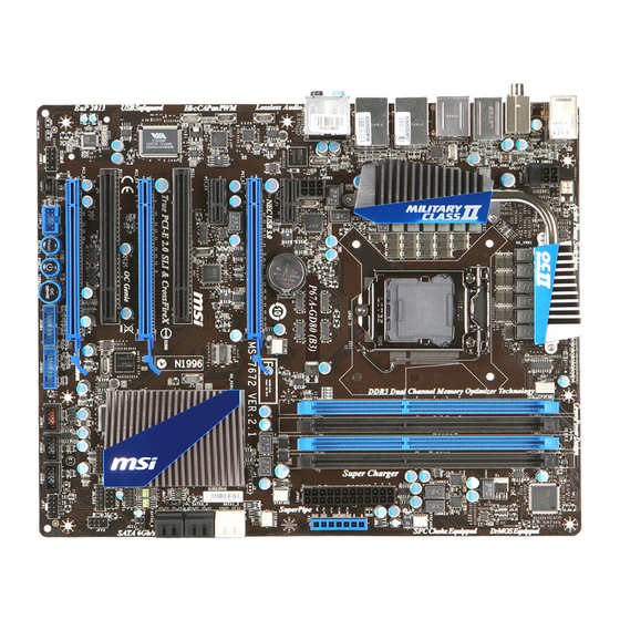
MS-7672 Mainboard MS-7672 Mainboard Quick Components Guide JPWR3, En-12 CPU, En-6 DDR3, En-10 JPWR2, En-12 SYSFAN1, En-16 CPUFAN1, En-16 SYSFAN2, En-16 JPWR1, En-12 Back Panel, En-13 SYSFAN3, En-16 FV1, En-22 JBAT1, En-23 SYSFAN4, En-16 SATA, En-15 PCIE, En-25 JTPM1, En-20 JCI1, En-19 JDLED3, En-16 PCI, En-25... -
Page 15: Screw Holes
Screw Holes When you install the mainboard, you have to place the mainboard into the chassis in the correct direction. The locations of screws holes on the mainboard are shown as below. The side has to toward the rear, the position for the I/O shield of the chassis. -
Page 16: Cpu (Central Processing Unit
When you are installing the CPU, make sure to install the cooler to prevent overheating. If you do not have the CPU cooler, consult your dealer before turning on the computer. For the latest information about CPU, please visit http://www.msi.com/index. php?func=cpuform2... -
Page 17: Cpu & Cooler Installation
CPU & Cooler Installation When you are installing the CPU, make sure the CPU has a cooler attached on the top to prevent overheating. Meanwhile, do not forget to apply some thermal paste on CPU before installing the heat sink/cooler fan for better heat dispersion. Follow the steps below to install the CPU &... - Page 18 MS-7672 Mainboard MS-7672 Mainboard Visually inspect if the CPU is seated Engage the load lever while pressing well into the socket. If not, take out down lightly onto the load plate. the CPU with pure vertical motion and reinstall. Alignment Key Secure the lever near the hook end Make sure the four hooks are in por- under the retention tab.
- Page 19 Align the holes on the mainboard with Press the four hooks down to fasten the heatsink. Push down the cooler the cooler. until its four clips get wedged into the holes of the mainboard. Turn over the mainboard to confirm Finally, attach the CPU Fan cable to that the clip-ends are correctly in- the CPU fan connector on the main-...
-
Page 20: Memory
MS-7672 Mainboard MS-7672 Mainboard Memory These DIMM slots are used for installing memory modules. For more information on compatible components, please visit http://www.msi.com/index.php?func=testreport DDR3 240-pin, 1.5V 48x2=96 pin 72x2=144 pin Dual-Channel mode Population Rule In Dual-Channel mode, the memory modules can transmit and receive data with two data bus lines simultaneously. -
Page 21: Installing Memory Modules
Installing Memory Modules The memory module has only one notch on the center and will only fit in the right orientation. Insert the memory module vertically into the DIMM slot. Then push it in until the golden finger on the memory module is deeply inserted in the DIMM slot. The plastic clip at each side of the DIMM slot will automatically close when the memory module is properly seated. -
Page 22: Power Supply
MS-7672 Mainboard MS-7672 Mainboard Power Supply ATX 24-pin Power Connector: JPWR1 This connector allows you to connect an ATX 24-pin power supply. To connect the ATX 24-pin power supply, make sure the plug of the power supply is inserted in the proper orientation and the pins are aligned. -
Page 23: Back Panel
Back Panel USB 2.0 Port IEEE 1394 Port Coaxial Keyboard/ Mouse S/PDIF-Out RS-Out Line-In CS-Out Line-Out SS-Out USB 2.0 Port Optical USB 3.0 Port USB 3.0 Port USB 3.0 Port S/PDIF-Out eSATA Port Clear CMOS button ▶ Mouse/Keyboard The standard PS/2 mouse/keyboard DIN connector is for a PS/2 mouse/keyboard. - Page 24 MS-7672 Mainboard MS-7672 Mainboard ▶ USB 2.0 Port The USB (Universal Serial Bus) port is for attaching USB devices such as keyboard, mouse, or other USB-compatible devices. ▶ USB 3.0 Port USB 3.0 port is backward-compatible with USB 2.0 devices. Supports data transfer rate up to 5 Gbit/s (SuperSpeed).
-
Page 25: Connectors
Connectors Serial ATA Connector: SATA1~6 This connector is a high-speed Serial ATA interface port. Each connector can connect to one Serial ATA device. * The MB layout in this figure is for reference only. SATA1~2 (6 Gb/s) SATA1_2 SATA3~6 (3 Gb/s) SATA3_4 SATA5_6 Important... - Page 26 CPUFAN1 speeds according to the actual CPUFAN1 tem- peratures. Fan cooler set with 3 or 4 pins power connector are both available for CPUFAN1. • DLED3 Connector: JDLED3 (optional) This is reserved for connecting the MSI future control card. En-16...
- Page 27 Front Panel Connectors: JFP1, JFP2 These connectors are for electrical connection to the front panel switches and LEDs. The JFP1 is compliant with Intel Front Panel I/O Connectivity Design Guide. ® JFP2 JFP1 Front USB 3.0 Connector: JUSB4/ JUSB5 USB 3.0 port is backward-compatible with USB 2.0 devices. Supports data transfer rate up to 5 Gbit/s (SuperSpeed).
- Page 28 Smartphone. If your system is in S0 / S1 state, you must install MSI’s application, SuperCharger, to control the JUSB1. When the application is set to “On”, it can fast charge Smartphone JUSB1 but the data transmission and synchronization will be disabled.
- Page 29 S/PDIF-Out Connector: JSP1 This connector is used to connect S/PDIF (Sony & Philips Digital Interconnect Format) interface for digital audio transmission. * The MB layout in this figure is for reference only. S/PDIF-Out Bracket (optional) Chassis Intrusion Connector: JCI1 This connector connects to the chassis intrusion switch cable. If the chassis is opened, the chassis intrusion mechanism will be activated.
- Page 30 MS-7672 Mainboard MS-7672 Mainboard TPM Module connector: JTPM1 This connector connects to a TPM (Trusted Platform Module) module (optional). Please refer to the TPM security platform manual for more details and usages. En-20...
- Page 31 Front Panel Audio Connector: JAUD1 This connector allows you to connect the front panel audio and is compliant with Intel ® Front Panel I/O Connectivity Design Guide. IEEE1394 Connector: J1394_1 This connector allows you to connect the IEEE1394 device via an optional IEEE1394 bracket.
- Page 32 MS-7672 Mainboard MS-7672 Mainboard Voltage Check Point: FV1 This voltage check point set is used to measure the current CPU core/ CPU IO/ CPU_ SA/ DDR/ PCH voltage. VCCP CPU_SA PCH_1P05 CPU_VTT VCC_DDR CPU core voltage: measure the current CPU core voltage with VCCP point and GND point by using a multimeter.
-
Page 33: Jumper
Jumper Clear CMOS Jumper: JBAT1 There is a CMOS RAM onboard that has a power supply from an external battery to keep the data of system configuration. With the CMOS RAM, the system can automatically boot OS every time it is turned on. If you want to clear the system configuration, set the jumper to clear data. -
Page 34: Buttons
MS-7672 Mainboard MS-7672 Mainboard Buttons This section will explain how to change your motherboard’s function through the use of following buttons. OC Genie Button: TURBO1 This button is used to auto-overclock for the system. Press this button to enable the OC Genie function when the system is in power off state, meanwhile, the button will light and lock. -
Page 35: Slots
Slots PCIE (Peripheral Component Interconnect Express) Slot The PCIE slot supports the PCIE interface expansion card. PCIE x16 Slot PCIE x1 Slot PCI (Peripheral Component Interconnect) Slot The PCI slot supports LAN card, SCSI card, USB card, and other add-on cards that comply with PCI specifications. -
Page 36: Led Status Indicators
MS-7672 Mainboard MS-7672 Mainboard LED Status Indicators CPU Phase LEDs These LEDs indicate the current CPU power phase mode. Follow the instructions below to read. Lights CPU is in 2 phase power mode. CPU is in 4 phase power mode. CPU is in 6 phase power mode. -
Page 37: Bios Setup
BIOS Setup This chapter provides basic information on the BIOS Setup program and allows you to configure the system for optimum use. You may need to run the Setup program when: ■ An error message appears on the screen during the system booting up, and requests you to run BIOS SETUP. - Page 38 MS-7672 Mainboard MS-7672 Mainboard Control Keyboard Mouse Description <↑ ↓ > Select Item Move the cursor <Enter> Select Icon/ Field Click/ Double- click the left but- <Esc> Jumps to the Exit menu or returns to the previous from a submenu Click the right button <+>...
- Page 39 The Main Menu Once you enter BIOS CMOS Setup Utility, the Main Menu will appear on the screen. The Main Menu allows you to select from the setup functions. ▶ Language After entering the Setup menu, you can see a “Language” button. Please click it and select the language, at your desire, for the BIOS setting first.
- Page 40 MS-7672 Mainboard MS-7672 Mainboard When enter the BIOS Setup utility, follow the processes below for general use. Load Optimized Defaults : Select [Settings] -> [Save & Exit] -> [Restore Defaults] and click on it. And then the screen shows a pop-up message as below. Select [Yes] and click on it to load the default settings for optimal system performance.
- Page 41 ▶ Adjusted CPU Frequency It shows the adjusted CPU frequency. Read-only. ▶ Adjust CPU Ratio in OS Enable this item, it will allow you to change the CPU ratio in OS by using MSI applica- tion. En-31...
- Page 42 MS-7672 Mainboard MS-7672 Mainboard ▶ EIST The Enhanced Intel SpeedStep technology allows you to set the performance level of the microprocessor whether the computer is running on battery or AC power. This field will appear after you installed the CPU which supports speedstep technology. ▶...
- Page 43 ▶ tRFC This setting determines the time RFC takes to read from and write to a memory cell. ▶ Minimum time interval between end of write data burst and the start of a precharge command. Allows sense amplifiers to restore data to cells. ▶...
- Page 44 MS-7672 Mainboard MS-7672 Mainboard ▶ VDroop Control This item is used to select the VDroop control mode. ▶ CPU Core Voltage/ CPU I/O Voltage/ DRAM Voltage/ System Agent Voltage (SA)/ CPU PLL Voltage/ DDR_VREF_CA_A/ DDR_VREF_CA_B/ DDR_VREF_DA_A/ DDR_ VREF_CA_B/ PCH 1.05 These items are used to adjust the voltage of CPU, Memory and chipset.
- Page 45 ▶ Intel Virtualization Tech This item is used to enable/disable the Intel Virtualization technology. For further information please refer to Intel’s official website. ▶ Power Technology This item allows you to select the Intel Dynamic Power technology mode. ▶ C1E Support To enable this item to read the CPU power consumption while idle.
-
Page 46: Software Information
Product info menu : It shows the newly information of MSI product. Security menu : It provides the useful antivirus program. Important Please visit the MSI officially website to get the latest drivers and BIOS for better system performance. En-36... -
Page 47: Deutsch
Deutsch P67A-GD80 Serie Europe Version... -
Page 48: Spezifikationen
MS-7672 Mainboard Spezifikationen Prozessoren ■ Intel Sandy Bridge Prozessor für Sockel LGA1155 ® (Weitere Informationen finden unter http://www.msi.com/index. php?func=cpuform2) Chipsatz ■ Intel P67 Chipsatz ® Speicher ■ 4 DDR3 DIMMs unterstützen DDR3 2133*(OC)/ 1600*(OC)/ 1333/ 1066 DRAM (max. 32GB) ■... - Page 49 PCI_E1 Slot zur Verfügung stellt. Hier empfehlen wir Ihnen nur einen PCIE x1 Steckplatz zu verwenden. ■ 2 PCI-Steckplätze Form Faktor ■ ATX (30,5 cm X 24,4 cm) Montage ■ 9 Montagebohrungen * Wenn Sie für Bestellungen von Zubehör Teilenummern benötigen, finden Sie diese auf unserer Produktseite unter http://www.msi.com/index.php De-3...
-
Page 50: Komponenten-Übersicht
MS-7672 Mainboard MS-7672 Mainboard Komponenten-Übersicht JPWR3, De-12 CPU, De-6 DDR3, De-10 JPWR2, De-12 SYSFAN1, De-16 CPUFAN1, De-16 SYSFAN2, De-16 JPWR1, De-12 Rücktafel, De-13 SYSFAN3, De-16 FV1, De-22 JBAT1, De-23 SYSFAN4, De-16 SATA, De-15 PCIE, De-25 JTPM1, De-20 JCI1, De-19 JDLED3, De-16 PCI, De-25 JFP1/JFP2, De-17 JAUD1, De-21... -
Page 51: Schraubenlöcher
Schraubenlöcher Wenn Sie das Mainboard zu installieren, müssen Sie das Mainboard in das Chassis in der korrekten Richtung setzen. Die Standorte von Schraubenlöchern auf dem Main- board sind wie nachfolgend gezeigt. Die Seite muss nach hinten, die Position für die E/A-Abschirmung des Chassis. -
Page 52: Cpu (Prozessor
Sie sich bitte mit Ihrem Händler in Verbindung, um einen solchen zu erwerben und zu installieren. Um die neuesten Informationen zu unterstützten Prozessoren zu erhalten, besuchen Sie bitte http://www.msi.com/index.php?func=cpuform2 Wichtig Überhitzung Überhitzung beschädigt die CPU und das System nachhaltig. Stellen Sie stets eine korrekte Funktionsweise des CPU Kühlers sicher, um die CPU vor Überhitzung zu... - Page 53 CPU & Kühler Einbau Wenn Sie die CPU einbauen, stellen Sie bitte sicher, dass Sie auf der CPU einen Kühler anbringen, um Überhitzung zu vermeiden. Vergessen Sie nicht, etwas Siliziumwärmel- eitpaste auf die CPU aufzutragen, bevor Sie den Prozessorkühler installieren, um eine Ableitung der Hitze zu erzielen.
- Page 54 MS-7672 Mainboard MS-7672 Mainboard Begutachten Sie, ob die CPU richtig Schließen Sie die Abdeckung des im Sockel sitzt. Falls nicht, zeihen Sie Sockels und drücken Sie den Ver- die CPU durch eine rein vertikale Be- schlusshebel mit leichtem Druck wegung wieder heraus. Versuchen nach unten.
- Page 55 Drücken Sie den Verschlusshebel Führen Sie den CPU-Kühler über mit leichtem Druck nach unten und den CPU-Sockel. arretieren Sie den Hebel unter dem Rückhaltehaken des CPU-Sockels. Drehen Sie das Mainboard um und Schließlich verbinden vergewissern Sie sich, dass das der Stromkabel des CPU Lüfters mit dem Kühler korrekt installiert ist.
-
Page 56: Speicher
MS-7672 Mainboard MS-7672 Mainboard Speicher Diese DIMM-Steckplätze nehmen Arbeitsspeichermodule auf. Die neusten Infor- mationen über kompatible Bauteile finden Sie unter http://www.msi.com/index. php?func=testreport DDR3 240-polig, 1,5V 48x2=96 Pole 72x2=144 Pole Populationsregeln für Dual-Kanal-Speicher Im Dual-Kanal-Modus können Arbeitsspeichermodule Daten über zwei Datenbusleitun- gen gleichzeitig senden und empfangen. - Page 57 Vorgehensweise beim Einbau von Speicher Modulen Die Speichermodulen haben nur eine Kerbe in der Mitte des Moduls. Sie passen nur in einer Richtung in den Sockel. Stecken Sie das Arbeitsspeichermodul senkrecht in den DIMM-Steckplatz ein. Drücken Sie anschließnd das Arbeitsspeichermodul nach unten, bis die Kontakt- seite richtig tief in dem DIMM-Steckplatz sitzt.
-
Page 58: Stromversorgung
MS-7672 Mainboard MS-7672 Mainboard Stromversorgung ATX 24-poliger Stromanschluss: JPWR1 Mit diesem Anschluss verbinden Sie den ATX 24-poligen Anschluss des Netzteils. Achten Sie bei dem Verbinden des ATX 24-poligen Stromanschlusses darauf, dass der Anschluss des Netzteils richtig auf den Anschluss an der Hauptplatine ausgerichtet ist. -
Page 59: Rücktafel
Rücktafel USB 2.0 Anschluss IEEE 1394 Koaxialer Anschluss S/PDIF- Maus/Tastatur Ausgang RS-Out Line-In CS-Out Line-Out SS-Out USB 2.0 Optischer USB 3.0 USB 3.0 USB 3.0 Anschluss Anschluss Anschluss S/PDIF- Anschluss eSATA Ausgang Anschluss CMOS leeren-Taste ▶ Maus/Tastatur Die Standard PS/2 Maus/Tastatur Stecker DIN ist für eine PS/2 Maus/Tastatur. - Page 60 MS-7672 Mainboard MS-7672 Mainboard ▶ USB 2.0 Anschluss Der USB (Universal Serial Bus) Anschluss zum direkten Anschluss von USB-Geräten, wie etwa Tastatur, Maus oder weiterer USB-kompatibler Geräte. ▶ USB 3.0 Anschluss Der USB 3.0 Anschluss ist abwärtskompatibel mit USB 2.0-Geräten. Unterstützt Daten- transferraten bis 5 Gbit/s (SuperSpeed).
-
Page 61: Anschlüssen
Anschlüssen Serial ATA Anschluss: SATA1~6 Der Anschluss ist eine Hochgeschwindigkeitsschnittstelle der Serial ATA. Pro An- schluss kann ein S-ATA Gerät angeschlossen werden. * Das MB-Layout in dieser Abbildung haben nur Orientierungscharakter. SATA1~2 (6 Gb/s) SATA1_2 SATA3~6 (3 Gb/s) SATA3_4 SATA5_6 Wichtig Bitte falten Sie das Serial ATA Kabel nicht in einem Winkel von 90 Grad, da dies zu Datenverlusten während der Datenübertragung führt. - Page 62 Geschwindigkeiten des CPUFAN1 in Abhängig- keit von der CPUFAN1 Temperaturen steuert. CPUFAN1 kann die Lüfter/Kühler mit drei- und vierpoligen Steckern unterstützen. • DLED3 Anschluss: JDLED3 (optional) Dieser Anschluss ist für Verbindung der zukünftigen Steuerkarte von MSI reserviert. De-16...
- Page 63 Frontpanel Anschlüsse: JFP1, JFP2 Diese Anschlüsse sind für das Frontpanel. Sie dienen zum Anschluss der Schalter und LEDs des Frontpanels. JFP1 erfüllt die Anforderungen des “Intel Front Panel I/O Con- ® nectivity Design Guide”. JFP2 JFP1 USB 3.0 Vorderanschluss: JUSB4/ JUSB5 Der USB 3.0 Anschluss ist abwärtskompatibel mit USB 2.0-Geräten.
- Page 64 JUSB1 unterstützt die neue Super-Charger-Technologie von MSI, die mit einer schnellen Ladefunktion jederzeit zum Aufladen Ihrer Smartphone bietet. Wenn Ihr System in Status S0 / S1 ist, müssen Sie das MSI-Anwendung, SuperCharg- er, zum Steuern des JUSB1 installieren. Wenn die Anwendung auf “On” gesetzt ist, kann sie den Smartphone über...
- Page 65 S/PDIF-Ausgang: JSP1 Die S/PDIF (Sony & Philips Digital Interconnect Format) Schnittstelle wird für die Über- tragung digitaler Audiodaten verwendet. * Das MB-Layout in dieser Abbildung haben nur Orientierungscharakter. S/PDIF-Ausgang Slotblech (optional) Gehäusekontaktanschluss: JCI1 Dieser Anschluss wird mit einem Kontaktschalter verbunden. Wird das Gehäuse geöff- net, wird der Schalter geschlossen und das System zeichnet dies auf und gibt auf dem Bildschirm eine Warnung aus.
- Page 66 MS-7672 Mainboard MS-7672 Mainboard TPM Anschluss: JTPM1 Dieser Anschluss wird für das optionale TPM Modul (Trusted Platform Module) ver- wendt. Weitere Informationen über den Einsatz des optionalen TPM Modules entnehm- en Sie bitte dem TPM Plattform Handbuch. De-20...
- Page 67 Audioanschluss des Frontpanels: JAUD1 Dieser Anschluss ermöglicht den Anschluss von Audioein und -ausgängen eines Front- panels. Der Anschluss entspricht den Richtlinien des “ Intel Front Panel I/O Connectiv- ® ity Design Guide”. IEEE1394 Anschluss: J1394_1 Mit diesem Anschluss verbinden Sie ein optionales IEEE 1394-Slotblech, das den An- schluss eines IEEE 1394-Gerätes ermöglicht.
- Page 68 MS-7672 Mainboard MS-7672 Mainboard Spannungsmesspunkte: FV1 Die Einstellung der Spannungsmesspunkte wird verwendet, um die gegenwärtige CPU Core/ CPU IO/ CPU_SA/ DDR/ PCH Spannung zu messen. VCCP CPU_SA PCH_1P05 CPU_VTT VCC_DDR CPU Core Spannung: Messen Sie die gegen- wärtige CPU Core Spannung mit VCCP Punkt und GND Punkt mit einem Multimeter.
-
Page 69: Steckbrücke
Steckbrücke Steckbrücke zur CMOS- Löschung: JBAT1 Der Onboard CMOS Speicher (RAM) wird über eine zusätzliche Betterie mit Strom versorgt, um die Daten der Systemkonfiguration zu speichern. Er ermöglicht es dem Betriebssystem, mit jedem Einschalten automatisch hochzufahren. Wenn Sie die Sys- temkonfiguration löschen wollen, müssen Sie die Steckbrücke für kurze Zeit umsetzen. -
Page 70: Tasten
MS-7672 Mainboard MS-7672 Mainboard Tasten Dieser Abschnitt beschreibt, wie man die Funktionen des Motherboards durch den Ge- brauch der Taste ändert. OC Genie Taste: TURBO1 Diese Taste wird zum Selbstübertaktung für das System benutzt. Drücken Sie diese Taste, um der OC Genie Funktion zu ermöglichen, wenn das System im spannung- slosen Zustand ist, unterdessen die Taste beleuchtet und sich verriegelt. -
Page 71: Steckplätze
Steckplätze PCIE (Peripheral Component Interconnect Express) Steckplatz Der PCIE-Steckplatz unterstützt eine Erweiterungskarte mit der PCIE-Schnittstelle. PCIE x16-Steckplatz PCIE x1-Steckplatz PCI (Peripheral Component Interconnect) Steckplatz Der PCI-Steckplatz kann LAN-Karten, SCSI-Karten, USB-Karten und sonstige Zusatz- karten aufnehmen, die mit den PCI-Spezifikationen konform sind. 32-Bit PCI Steckplatz Wichtig Achten Sie darauf, dass Sie zuerst das Netzkabel aus der Steckdose herausziehen,... -
Page 72: Led Statusanzeige
MS-7672 Mainboard MS-7672 Mainboard LED Statusanzeige CPU Phase LEDs Diese LEDs zeigen den gegenwärtigen CPU Auslastungsgrad an. Lesen Sie die folgen- den Anweisungen. Leuchtet CPU ist in der Phase 2 des Power-Modus. CPU ist in der Phase 4 des Power-Modus. CPU ist in der Phase 6 des Power-Modus. -
Page 73: Bios Setup
BIOS Setup Dieses Kapitel enthält Informationen über das BIOS Setup und ermöglicht es Ihnen, Ihr System optimal auf Ihre Anforderungen einzustellen. Notwendigkeit zum Aufruf des BIOS besteht, wenn: ■ Während des Bootvorgangs des Systems eine Fehlermeldung erscheint und Sie zum Aufruf des BIOS SETUP aufgefordert werden. ■... - Page 74 MS-7672 Mainboard MS-7672 Mainboard Steuertasten Tastatur Maus Beschreibung <↑ ↓ > Auswahl eines Eintrages Bewegen Sie den Cursor <Enter> Auswahl eines Symbols/ Feldes Klicken/ dop- pelt-klicken Sie mit der linken Maustaste <Esc> Aufruf Exit Menü oder zurück zum Hauptmenü von Untermenü...
- Page 75 Das Hauptmenü Nachdem Sie das BIOS CMOS Setup Utility, aufgerufen haben, erscheint das Haupt- menü. Das Hauptmenü können Sie von der Setup-Funktionen auswählen. ▶ Language Nach der Eingabe des Einstellungsmenü können Sie eine Schaltfläche “Language”. Bitte klicken Sie darauf und wählen Sie die Sprache für die BIOS-Einstellung. ▶...
- Page 76 MS-7672 Mainboard MS-7672 Mainboard Wenn Sie das BIOS Dienstprogramm öffnen, folgen Sie den untenstehenden An- weisungen. Laden der gespeicherten Werkseinstellung : Wählen Sie [Settings] -> [Save & Exit] -> [Restore Defaults] und klicken auf diese Schaltfläche. Und dann zeigt der Bild- schrim die folgende PopUp-Meldung.
- Page 77 ▶ Adjusted CPU Frequency Gibt die Frequenz der CPU an. Nur Anzeige – keine Änderung möglich. ▶ Adjust CPU Ratio in OS Aktivieren Sie dieses Element, können Sie die CPU-Verhältnis im Betriebssystem än- dern, indem Sie die MSI-Anwendung verwenden. De-31...
- Page 78 MS-7672 Mainboard MS-7672 Mainboard ▶ EIST Die erhöhte Intel SpeedStep Technologie erlaubt Ihnen, den Leistungsgrad des Mi- kroprozessors einzustellen, ob der Computer auf Wechselstrom läuft. Dieses Figur erscheint, nachdem Sie das CPU anbringen, das Speedstep Technologie stützen. ▶ Intel Turbo Boost Das Untermenü...
- Page 79 ▶ tRFC Diese Einstellung definiert die Zeit (RFC) zum Lesen und Schreiben einer Speicher- zelle. ▶ Minimum Intervall zwischen dem Datenflussende und dem Beginn eines vorgelad- enen Befehls. Erlaubt die Wiederherstellung der Daten in die Zellen. ▶ tWTR Minimum Intervall zwischen dem Datenflussende und dem Beginn eines Spaltenle- sebefehls.
- Page 80 MS-7672 Mainboard MS-7672 Mainboard ▶ VDroop Control Hier können Sie die VDroop Steuermodi auswählen. ▶ CPU Core Voltage/ CPU I/O Voltage/ DRAM Voltage/ System Agent Voltage (SA)/ CPU PLL Voltage/ DDR_VREF_CA_A/ DDR_VREF_CA_B/ DDR_VREF_DA_A/ DDR_ VREF_CA_B/ PCH 1.05 Diese Option bietet Ihnen an, die Spannung der CPU, des Speichers und des Chipsatz anzupassen.
- Page 81 reichen des Speicher Behle ausgeführt und welche blockiert werden können. Wird ein schadhafter Befehl in den Speicher geladen verhindert die CPU-Funktion die Ausführung des Befehls, um vor Schäden oder Verbreitung von Viren / Würmern zu schützen. ▶ Intel Virtualization Tech Hier können Sie die Intel Virtualisierungs-Technologie aktivieren/ deaktivieren.
-
Page 82: Software-Information
Produktinformation-Menü : Es zeigt die neu Informationen von MSI Produkt. Sicherheits-Menü : Es bietet die nützliche Antivirenprogramm. Wichtig Besuchen Sie bitte die offizielle Website des MSI, um die neuesten Treiber und BIOS für bessere System Leistung zu erhalten. De-36... -
Page 83: Français
Français P67A-GD80 Séries Europe version... -
Page 84: Spécifications
Carte mère MS-7672 Spécifications Processeurs Supportés ■ Intel Sandy Bridge processeurs dans le paquet LGA1155 ® (Pour plus d'information sur le CPU, veuillez visiter http://www.msi.com/index. php?func=cpuform2) Jeu de puces ■ Puces Intel ® Mémoire supportée ■ 4 DDR3 DIMMs supportent DDR3 2133*(OC)/ 1600*(OC)/ 1333/ 1066 DRAM (32GB Max) ■... - Page 85 ATX (30.5 cm X 24.4 cm) Montage ■ 9 trous de montage * Si vous désirez acheter des accessoires et vous avez besoin de numéros des pièces, vous pouvez chercher sur la page website et trouver les détails sur notre adresse ci- dessous http://www.msi.com/index.php Fr-3...
-
Page 86: Guide Rapide Des Composants
Carte mère MS-7672 Guide Rapide Des Composants JPWR3, Fr-12 CPU, Fr-6 DDR3, Fr-10 JPWR2, Fr-12 SYSFAN1, Fr-16 CPUFAN1, Fr-16 SYSFAN2, Fr-16 JPWR1, Fr-12 Panneau arrière, Fr-13 SYSFAN3, Fr-16 FV1, Fr-22 JBAT1, Fr-23 SYSFAN4, Fr-16 SATA, Fr-15 PCIE, Fr-25 JTPM1, Fr-20 JCI1, Fr-19 JDLED3, Fr-16 PCI, Fr-25... -
Page 87: Trous Taraudés
Trous Taraudés Quand vous installez la carte mère, il faut déposer la carte dans le châssis en bonne position. La situation des trous taraudés sont montrée dans la figure ci-dessous. Face vers l’arrière, position pour protège Entré/ Sor- tie du châssis. Trous taraudés Veuillez vous référer à... -
Page 88: Processeur : Cpu
Quand vous installez le CPU, veuillez vous assurer d’installer un ventilateur pour éviter la surchauffe. Si vous n’en avez pas, contactez votre revendeu pour en acheter et in- stallez-les avant d’allumer votre ordinateur. Pour plus d’informations sur le CPU, veuillez visiter http://www.msi.com/index. php?func=cpuform2 Important Surchauffe La surchauffe endommage sérieusement l’unité... -
Page 89: Installation Du Cpu Et Son Ventilateur
Installation du CPU et son ventilateur Quand vous installez le CPU, assurez-vous que le CPU soit équipé d’un ventilateur de refroidissement attaché sur le dessus pour éviter la surchauffe. Méanmoins, n’oubliez pas d’appliquer une couche d’enduit thermique sur le CPU avant d’installer le ventila- teur pour une meilleure dissipation de chaleur. - Page 90 Carte mère MS-7672 Inspectez visuellement si le CPU Engagez le levier de charge en ap- est bien posé dans la douille. Sinon, puyant doucement sur le plaque de sortez verticalement le CPU pur et la charge. réinstallez. Clé d’alignement Sécurisez le levier à côté du bout de Assurez-vous que les quatre cro- crochet sous l’onglet de rétention.
- Page 91 Alignez les trous de la carte avec le Appuyez sur les quatre crochets afin dissipateur thermique. Appuyez sur de fixer le ventilateur. le ventilateur jusqu’à ce que les clips soient coincés dans les trous de la carte mère. Retournez la carte mère pour as- Finalement, attachez le câble du surer que le ventilateur est installé...
-
Page 92: Mémoire
Carte mère MS-7672 Mémoire Ces emplacements DIMM sont destinés à installer les modules de mémoire. Pour plus d’informations sur les composants compatibles, veuillez visiter http://www.msi.com/in- dex.php?func=testreport DDR3 240-pin, 1.5V 48x2=96 pin 72x2=144 pin Règles de population de la mémoire En mode de canaux-double, les modules de mémoire peuvent transmettre et recevoir les données avec simultanément deux lignes omnibus de données. - Page 93 Installation des modules de mémoire Le module de mémoire possède une seule encoche en son centre et ne s’adaptera que s’il est orienté de la mqnière convenable. Insérez le module de mémoire à la verticale dans le slot du DIMM. Poussez-le en- suite jusqu’à...
-
Page 94: Connecteurs D'alimentation
Carte mère MS-7672 Connecteurs d’alimentation Connecteur d’alimentation ATX 24-pin : JPWR1 Ce connecteur vous permet de connecter l’alimentation ATX 24-pin. Pour cela, as- surez-vous que la prise d’alimentation est bien positionnée dans le bon sens et que les goupilles soient alignées. Enfoncez alors la prise dans le connecteur. Connecteur d’alimentation du ATX 8-pin : JPWR2 Ce connecteur d’alimentation sert à... -
Page 95: Panneau Arrière
Panneau arrière Port USB 2.0 Port IEEE 1394 S/PDIF-Out Clavier/ Souris coaxial RS-Out Ligne-In CS-Out Ligne-Out SS-Out Port USB 2.0 S/PDIF-Out Port USB 3.0 Port USB 3.0 Port USB 3.0 optique Port eSATA Bouton d’effacement CMOS ▶ Souris/Clavier Le standard connecteur de souris/clavier DIN de PS/2 est pour une souris ou un clavier ®... - Page 96 Carte mère MS-7672 ▶ Port USB 2.0 Le port USB (Universal Serial Bus) sert à brancher des périphériques USB tels que le clavier, la souris, ou d’autres périphériques compatibles USB. ▶ Port USB 3.0 Le port USB 3.0 est inférieur-compatible avec les périphériques USB 2.0. Il supporte le taux de transfert jusqu'à...
-
Page 97: Connecteurs
Connecteurs Connecteur Sérial ATA : SATA1~6 Ce connecteur est un port d’interface de série ATA haut débit. Chaque connecteur peut être relié à un appareil de série ATA. * Le schéma de carte mère dans la figure n’est qu’à titre de référence. SATA1~2 (6 Gb/s) SATA1_2 SATA3~6 (3 Gb/s) - Page 98 Carte mère MS-7672 Connecteur d’alimentation du ventilateur : CPUFAN1,SYSFAN1~4 Les connecteurs de courant du ventilateur supportent le ventilateur de refroidissement du système avec +12V. Lors du branchement des fils aux connecteurs, faites toujours en sorte que le fil rouge soit le fil positif devant être relié au connecteur +12V; et que le fil noir soit le fil de mise à...
- Page 99 Connecteur panneau avant : JFP1, JFP2 Ce connecteur est fourni pour la connecxion électrique aux interrupteuts et LEDs du panneau avant. Le JFP1 est conforme au guide de conception de la connectivité En- trée/sortie du panneau avant Intel ® JFP2 JFP1 Connecteur USB 3.0 avant : JUSB4/ JUSB5 Le port USB 3.0 est inférieur-compatible avec les périphériques USB 2.0.
- Page 100 à tout moment pour charge votre Smartphone. Si votre système est en état S0 / S1, il est nécessaire d’installer l’application MSI, Su- perCharger, de manière à contrôler le JUSB1. Lorsque l’application est mise en “On”,...
- Page 101 Connecteur S/PDIF-Out : JSP1 Ce connecteur sert à connecter l’interface S/PDIF (Sony & Philips Digital Interconnect Format) pour une transmission audio numérique. * Le schéma de carte mère dans la figure n’est qu’à titre de référence. Support S/PDIF-Out (en option) Connecteur Châssis Intrusion : JCI1 Ce connecteur est connecté...
- Page 102 Carte mère MS-7672 Connecteur de Module TPM : JTPM1 Ce connecteur est rélié à TPM (Trusted Platform Module) Module (en option). Veuillez vous référer au manuel de TPM plat-forme (en option) de sécurité pour plus de détails et d’utilisations. Fr-20...
- Page 103 Connecteur audio panneau avant : JAUD1 Ce connecteur vous permet de connecter un audio sur le panneau avant.Il est conforme au guide de conception de la connectivité Entrée/sortie du panneau avant Intel ® Connecteur IEEE1394 : J1394_1 Ce connecteur vous permet de relier un appareil IEEE 1394 via un support en option IEEE1394.
- Page 104 Carte mère MS-7672 Point de vérification de tension : FV1 Cet équipement de point de vérification sert à mesurer la tension actuelle CPU core/ CPU IO/ CPU_SA/ DDR/ PCH. VCCP CPU_SA PCH_1P05 CPU_VTT VCC_DDR Tension CPU cœur : mesurer la tension actuelle du CPU cœur avec le point VCCP et le point GND à...
-
Page 105: Jumper
Jumper Cavalier d’effacement CMOS : JBAT1 Il y a un CMOS RAM intégré, qui possède un bloc d’alimentation alimenté par une bat- terie externe, destiné à conserver les données de configuration du système. Avec le CMOS RAM, le système peut lancer automatiquement le système d’exploitation chaque fois qu’il est allumé. -
Page 106: Bouton
Carte mère MS-7672 Bouton Cette section vous explique comment changer la fonction de votre carte mère avec ces boutons. Bouton OC Genie : TURBO1 Ce bouton sert à auto-overclocker pour le système. Appuyez sur ce bouton pour activer la fonction OC Genie lorsque le système est au statut éteint, néanmoins, le bouton s’allume et se verrouille. -
Page 107: Emplacements
Emplacements Emplacement PCIE (Peripheral Component Interconnect Express) L’emplacement PCIE supporte la carte d’extension d’Interface PCIE. Emplacement PCIE x16 Emplacement PCIE x1 Emplacement PCI (Peripheral Component Interconnect) L’emplacement PCI supporte la carte LAN, la carte SCSI, la carte USB et d’autres cartes ajoutées qui sont compatibles avec les spécifications de PCI. -
Page 108: Indicateur De Statut Led
Carte mère MS-7672 Indicateur de statut LED CPU Phase LEDs Ces LEDs indiquent le mode actuel de phase d’alimentation CPU. Suivez les instruc- tions ci-dessous pour le lire. Allumé Eteint CPU est au mode d’alimentation de phase 2. CPU est au mode d’alimentation de phase 4. CPU est au mode d’alimentation de phase 6. -
Page 109: Réglage Bios
Réglage BIOS Ce chapitre donne des informations concernant le programme de réglage de BIOS et vous permet de configurer le système pour obtenir des performances d’utilisation opti- mum. Vous aurez peut-être besoin de lancer le programme de réglage quand : ■... - Page 110 Carte mère MS-7672 Contrôle Clavier Souris Description <↑ ↓ > Choisir un article Bouger le cur- seur <Entrer> Choisir une icône/ un domaine Cliquer/ Double- cliquer le bouton gauche <Esc> Retourner au menu Exit ou revenir à la page précé- dente d’un sous-menu Cliquer le bouton droite...
- Page 111 Menu principal Une fois entré dans l’unité de réglages BIOS CMOS, le menu principal apparaît sur l’écran. Le Menu Principal vous permet de sélectionner parmi les fonctions de réglag- ▶ Language Entrez dans le menu Setup, vous voyez un bouton “Language”. Veuillez cliquer ce bou- ton et choisir la langue selon vos souhaits, pour le réglage BIOS d’abord.
- Page 112 Carte mère MS-7672 Quand vous entrez dans l’unité de réglages BIOS, suivez les procédures suivantes pour l’utilisation générale. Load Optimized Defaults (Chargement des réglages optimisés par défaut) : Choi- sissez [Settings] -> [Save & Exit] -> [Restore Defaults] et cliquez. Puis apparaît un message sur l’écran comme ci-dessous.
- Page 113 ▶ Adjusted CPU Frequency Il montre la fréquence ajustée du CPU. Lecture uniquement. ▶ Adjust CPU Ratio in OS Activer ce menu, il vous permettra de changer le ratio CPU dans le système d’exploitation à l’aide de l’application MSI. Fr-31...
- Page 114 Carte mère MS-7672 ▶ EIST L’Enhanced Intel SpeedStep Technologie vous permet de configurer le niveau de per- formance du microprocesseur. Ce menu vous apparaîtra seulement si vous installiez un CPU qui supporte la technologie speedstep. ▶ Intel Turbo Boost Cet article apparaît lorsque vous installez un CPU supportant l’Intel Turbo Boost Tech- nologie.
- Page 115 ▶ tRFC Ce réglage détermine le temps que RFC prend pour lire ou écrire une cellule de mémoire. ▶ L’intervalle de temps minimum entre la fin d’apparition d’écriture de données et le début de l’ordre de précharge. Permet aux amplificateurs sensitifs de restaurer les données aux cellules.
- Page 116 Carte mère MS-7672 ▶ VDroop Control Ce menu sert à choisir un mode de contrôle VDroop. ▶ CPU Core Voltage/ CPU I/O Voltage/ DRAM Voltage/ System Agent Voltage (SA)/ CPU PLL Voltage/ DDR_VREF_CA_A/ DDR_VREF_CA_B/ DDR_VREF_DA_A/ DDR_ VREF_CA_B/ PCH 1.05 Ces menus servent à ajuster la tension du CPU, de la mémoire et des puces. ▶...
- Page 117 prévenir le dommage ou la propagation du ver. ▶ Intel Virtualization Tech Ce menu sert à activer/ désactiver l’Intel Virtualization Technologie. Pour plus d’informations veuillez vous référer au site officiel d’Intel. ▶ Power Technology Cet article vous permet de choisir le mode Intel Dynamic Power technologie. ▶...
-
Page 118: Information Logiciel
Menu d’information du produit : Il montre les nouvelles informations sur le produit MSI. Menu de sécurité : Il fournit la programme d’antivirus. Important Veuillez consulter le site Web de MSI pour obtenir les derniers pilotes et BIOS pour une meilleure performance du système. Fr-36... -
Page 119: Русский
Русский Серия P67A-GD80 Europe version... -
Page 120: Характеристики
MS-7672 Системная плата Характеристики Процессор ■ Процессор Intel Sandy Bridge в конструктиве LGA1155 ® (Для получения самой новой информации о CPU, посетите сайт http://www.msi.com/index.php?func=cpuform2) Чипсет ■ Intel ® Память ■ 4 слота DDR3 DIMM поддерживают скорость DDR3 2133*(OC)/ 1600*(OC)/ 1333/ 1066 DRAM (32ГБ... - Page 121 доступен, рекомендуется использовать слот PCIE x1. ■ 2 слота PCI Форм Фактор ■ ATX (30.5 см X 24.4 см) Крепление ■ 9 отверстий для крепления * Помощь в приобретении дополнительных аксессуаров и поиске номера изделия можно найти по адресу http://www.msi.com/index.php Ru-3...
-
Page 122: Размещение Компонентов Системной Платы
MS-7672 Системная плата MS-7672 Системная плата Размещение компонентов системной платы JPWR3, Ru-12 CPU, Ru-6 DDR3, Ru-10 JPWR2, Ru-12 SYSFAN1, Ru-16 CPUFAN1, Ru-16 SYSFAN2, Ru-16 JPWR1, Ru-12 Задняя панель, Ru-13 SYSFAN3, Ru-16 FV1, Ru-22 JBAT1, Ru-23 SYSFAN4, Ru-16 SATA, Ru-15 PCIE, Ru-25 JTPM1, Ru-20 JCI1, Ru-19 JDLED3, Ru-16... -
Page 123: Отверстия Для Винтов
Отверстия для винтов При установке системной платы нужно вставить её в корпус в правильном направлении. Размещения отверстий для винтов показаны ниже. Боковые стороны следует против заднего корпуса, размещение для протектора входа/ выхода корпуса. Отверстия для винтов Следуйте указаниям выше указанно для установки держателей в правильном месте в... -
Page 124: Cpu (Центральный Процессор
установить процессорный кулер. Если у вас нет процессорного кулера, пожалуйста, свяжитесь с дилером с целью приобретения и его установки до того, как включите компьютер. Последнюю информацию о поддержке процессоров можно получить на сайте http://www.msi.com/index.php?func=cpuform2 Внимание Перегрев Перегрев может серьёзно повредить центральный процессор. Чтобы уберечь... - Page 125 Установка процессора и вентилятора Во избежание перегрева при работе обязательно установите вентилятор процессора. Одновременно, чтобы улучшить теплоотвод, убедитесь в том, что нанесён слой теплопроводящей пасты на процессоре перед установкой вентилятора. Следуйте данным указаниям для правильной установки. Неправильная установка приведет к повреждению процессора и системной платы. Потяните...
- Page 126 MS-7672 Системная плата MS-7672 Системная плата Визуально проверьте правильность Опустите металлическую крышку установки процессора в разъем. механизма крепления. Если процессор установлен неправильно, то выньте процессор и переустановите. Ключ для установки Опустите рычаг на крышку Перед установкой вентилятора механизма крепления и убедитесь, что...
- Page 127 Совместите отверстия системной Нажмите на четыре защелки и платы с защелками крепления закрепите вентилятор. вентилятора. Прижмите радиатор с вентилятором к процессору и проследите, чтобы четыре защелки вошли в отверстия системной платы. Переверните системную плату и По завершении подключите кабель убедитесь, что защелки надежно вентилятора...
-
Page 128: Память
MS-7672 Системная плата MS-7672 Системная плата Память Слоты DIMM используются для установки модулей памяти. За дополнительной информацией о совместимых компонентах обратитесь на сайт http://www.msi.com/index.php?func=testreport DDR3 240-конт, 1.5V 48x2=96 конт 72x2=144 конт Правила установки модулей памяти для работы в двухканальном режиме... - Page 129 Установка модулей памяти Модули памяти имеют одну прорезь в средней части. Модуль войдет в разьем только при правильной ориентации. Вставьте модуль в DIMM слот в вертикальном направлении. Затем нажмите на него, чтобы золоченые контакты глубоко погрузились в DIMM слот. Если модуль...
-
Page 130: Разъем Питания
MS-7672 Системная плата MS-7672 Системная плата Разъем питания 24-контактный разъем питания ATX: JPWR1 Этот разъем позволяет подключить 24-контактный коннектор питания ATX. Для его подключения убедитесь, что коннектор и контакты разъема правильно сориентированы. Затем плотно вставьте его в разъем на системной плате. 8-контактный... -
Page 131: Задняя Панель
Задняя панель Порт USB 2.0 Разъем Порт IEEE 1394 Разъем Порт мыши/ Разъем коаксиальный клавиатуры S/PDIF-Out Линейный RS-выход вход Линейный CS-выход выход SS-выход Микрофон Разъем Порт USB 2.0 Порт USB 3.0 Порт USB 3.0 Порт USB 3.0 оптический Порт eSATA S/PDIF-Out Кнопка... - Page 132 MS-7672 Системная плата MS-7672 Системная плата ▶ Порт USB 2.0 USB порт (Universal Serial Bus) позволяет подключать такие USB устройства, как клавиатура, мышь и т.д. Поддержка скорости передачи данных до 480Мб/с (Hi- Speed). ▶ Порт USB 3.0 Порт USB 3.0 является обратно совместимым устройством с USB 2.0. Поддержка скорости...
-
Page 133: Коннекторы
Коннекторы Разъем Serial ATA: SATA1~6 Данный разъем является высокоскоростным портом интерфейса Serial ATA. Любой разъем Serial ATA может соединяться с одним устройством Serial ATA. * Компоненты системной платы в изображении только для справки. SATA1~2 (6 Гб/с) SATA1_2 SATA3~6 (3 Гб/с) SATA3_4 SATA5_6 Внимание... - Page 134 автоматического контроля скорости вентилятора процессора, зависящей от температуры процессора и системы, можно установить Control Center. Разъем CPUFAN1 поддерживает вентиляторы, как с 3, так и с 4 контактами. • Разъем DLED3: JDLED3 (опционально) Этот разъем зарезервирован для подключения контрольной карты MSI в будущем. Ru-16...
- Page 135 Коннекторы передней панели: JFP1, JFP2 Эти коннекторы используются для подключения кнопок и индикаторов, расположенных на передней панели корпуса. Коннектор JFP1 соответствует руководству Intel Front Panel I/O Connectivity Design. ® JFP2 JFP1 Разъем USB 3.0 передней панели: JUSB4/ JUSB5 Порт USB 3.0 является обратно совместимым устройством с USB 2.0. Поддержка скорости...
- Page 136 поддерживает новую технологию Super-Charger MSI, которая обеспечивает функцию быстрой зарядки в люлое время для вашего смартфона. Когда система под состоянием S0 / S1, вам нужно установить приложение MSI, SuperCharger, чтобы контролировать JUSB1. При установке приложения в “On” (Включен), он быстро зарядит смартфон через...
- Page 137 Разъем S/PDIF-Out: JSP1 Этот разъем используется для подключения интерфейса S/PDIF (Sony & Philips Digital Interconnect Format) для передачи звука в цифровом формате. * Компоненты системной платы в изображении только для справки. Выносная планка S/PDIF-Out (опционально) Разъем датчика открывания корпуса: JCI1 К...
- Page 138 MS-7672 Системная плата MS-7672 Системная плата Разъем TPM Модуля: JTPM1 Данный разъем подключается к модулю TPM (Trusted Platform Module) (опционально). За более подробной информацией и назначениями обращайтесь к описанию модуля TPM. Ru-20...
- Page 139 Выносной разъем аудио: JAUD1 Этот коннектор позволяет подключить выносной разъем аудио на передней панели и соответствует руководству Intel Front Panel I/O Connectivity Design. ® Разъем IEEE1394: J1394_1 Этот коннектор позволяет подключить порты IEEE1394 на опциональной выносной планке IEEE1394. * Компоненты системной платы в изображении только для справки. Выносная...
- Page 140 MS-7672 Системная плата MS-7672 Системная плата Voltage Check Point: FV1 Данные контрольные точки используются для измерения текущего напряжения CPU core/ CPU IO/ CPU_SA/ DDR/ PCH. VCCP CPU_SA PCH_1P05 CPU_VTT VCC_DDR Напряжение core: для измерения текущего напряжения CPU core необходимо коснуться точек VCCP и GND щупами VCCP тестера.
-
Page 141: Перемычки
Перемычки Перемычки очистки CMOS: JBAT1 На плате установлена CMOS память с питанием от батарейки, хранящая данные о конфигурации системы. С помощью памяти CMOS, система автоматически загружается каждый раз при включении. Если у вас возникает необходимость сбросить конфигурацию системы (очистить CMOS), воспользуйтесь этой перемычкой. -
Page 142: Кнопки
MS-7672 Системная плата MS-7672 Системная плата Кнопки Эта глава поясняет возможности каждой из кнопок. Кнопка OC Genie: TURBO1 Эта кнопка используется для автоматического разгона системы. Нажмите эту кнопку для включения функции OC Genie, когда система выключена. После нажатия кнопка фиксируется и будет подсвечена. Система автоматически определит... -
Page 143: Слоты
Слоты Слот PCIE (Peripheral Component Interconnect Express) Слот PCIE поддерживает карты расширения интерфейса PCIE. PCIE x16 слот PCIE x1 слот Слот PCI (Peripheral Component Interconnect) Слот PCI позволяет установить карты LAN, SCSI, USB и другие дополнительные карты расширения, которые соответствуют спецификации PCI. 32-bit PCI слот... -
Page 144: Световые Индикаторы
MS-7672 Системная плата MS-7672 Системная плата Световые индикаторы Индикаторы фаз CPU (CPU Phase LEDs) Эти индикаторы показывают режим работы источника питания CPU. Информация о состоянии индикаторов приведена в таблице. ВКЛЮЧЕН ВЫКЛЮЧЕН CPU использует 2 фазы питания. CPU использует 4 фазы питания. CPU использует... -
Page 145: Настройка Bios
Настройка BIOS В этой главе приводятся основные сведения о режиме настройки BIOS (BIOS SETUP), который позволяет установить оптимальную конфигурацию системы. Этот режим может потребоваться в следующих случаях: ■ Во время загрузки системы появляется сообщение об ошибке с требованием запустить BIOS SETUP. ■... - Page 146 MS-7672 Системная плата MS-7672 Системная плата Контроль Клавиатура Мышь Описание <↑ ↓ > Выбор пункт Перемещение курсора <Enter> Выбор значка/ области Щелчок/ Двойной щелчок левой кнопки <Esc> Переход в меню Выход или возвращение к предыдущему пункту в подменю Щелчок правой кнопки...
- Page 147 The Main Menu (Главное меню) При входе в режим настройки BIOS на экране отображается Главное меню. Главное меню позволяет выбрать следующие функций настроек. ▶ Language Пункт меню, в котором можно изменить текущий язык BIOS. ▶ Green Power Пункт меню, в котором можно изменить настройки режимов энергосбережения. ▶...
- Page 148 MS-7672 Системная плата MS-7672 Системная плата Находясь в режиме настройки BIOS, рекомендуется выполнить следующие действия. Load Optimized Defaults : Выберите пункт [Settings] -> [Save & Exit] -> [Restore Defaults] . На экране появится всплывающее сообщение как на картинке. Нажмите [Yes], чтобы загрузить настройки по умолчанию для оптимальной производительности...
- Page 149 частотой или частотой системной платы. Он доступен только тогда, когда процессор поддерживает эту функцию. ▶ Adjusted CPU Frequency Этот пункт показывает текущую частоту CPU. Только для чтения. ▶ Adjust CPU Ratio in OS Включение этого пункта позволяет изменять тактовую частоту CPU в OS средством приложения MSI. Ru-31...
- Page 150 MS-7672 Системная плата MS-7672 Системная плата ▶ EIST Технология Enhanced Intel SpeedStep позволяет установить уровень производительности микропроцессора. Этот пункт появляется после установки процессора, который поддерживает технологию SpeedStep. ▶ Intel Turbo Boost Этот пукнт появляется, когда вы установили CPU, поддерживающий технологию Intel Turbo Boost.
- Page 151 ▶ tRFC Эта установка определяет время, которое RFC затрачивает на чтение и запись в ячейку памяти. ▶ Минимальная временная задержка для выполнения операции записи перед командой предзаряда. Позволяет усилителям считывания записать данные в ячейки памяти. ▶ tWTR Минимальная временная задержка между выполнением команды записи и началом...
- Page 152 MS-7672 Системная плата MS-7672 Системная плата ▶ VDroop Control Этот пункт используется для выбора режима VDroop control. ▶ CPU Core Voltage/ CPU I/O Voltage/ DRAM Voltage/ System Agent Voltage (SA)/ CPU PLL Voltage/ DDR_VREF_CA_A/ DDR_VREF_CA_B/ DDR_VREF_DA_A/ DDR_ VREF_CA_B/ PCH 1.05 Эти...
- Page 153 программа попытается вставить код в буфер, процессор запретит исполнение кода, что остановит распространение вредоносной программы. ▶ Intel Virtualization Tech Этот пункт используется для включения/выключения технологии Intel Virtualiza- tion. За дополнительной информацией смотрите оффициальный вебсайт Intel. ▶ Power Technology Этот пункт позволяет выбрать режим технологии Intel Dynamic Power. ▶...
-
Page 154: Сведения О Программном Обеспечении
Service base menu (Меню сервисной базы): Позволяет соединить официальный вебсайт MSI. Product info menu (Меню продуктов): Показывает последнюю информацию о продуктах MSI. Security menu (Меню безопасности): Представляет полезные антивирусные программы. Внимание Пожалуйста, посетите вебсайт MSI для получения самых новых драйверов и BIOS, которые позволят улучшить производительность системы. Ru-36...
Need help?
Do you have a question about the P67A-GD80 series and is the answer not in the manual?
Questions and answers