Table of Contents
Advertisement
Quick Links
Advertisement
Table of Contents

Related Manuals for AIS IP10IA99 series


Summary of Contents for AIS IP10IA99 series
-
Page 1: User Manual
USER MANUAL OPEN HMI USER MANUAL... - Page 2 Human Machine Interface Panel 10.4" / 15" / 17” IP10IA99 / IP15IA99 / IP17IA99 Panel PC series...
-
Page 3: Table Of Contents
Table of Contents 1. Introduction -----------------------------------------------------------------------------------------5 1.1. Symbols used in this Manual -----------------------------------------------------------------------------------------7 2. Important Instructions ----------------------------------------------------------------------------------------------8 2.1. Note on the Warranty ---------------------------------------------------------------------------------------------------------- 8 2.2. Exclusion of Accident Liability Obligation----------------------------------------------------------------------------------- 8 2.3. Liability Limitation / Exemption from the Warranty Obligation ------------------------------------------------------ 8 3. - Page 4 6.1.4. Serial ATA Hard Disk Installation.------------------------------------------------------------------------------------------ 35 6.1.5. CF Card Installation ---------------------------------------------------------------------------------------------------------- 36 6.1.6. DC Power Input Installation ----------------------------------------------------------------------------------------------- 37 6.2. Panel and External AC/DC Adapter Mounting----------------------------------------------------------------------------- 37 6.2.1. Panel Mounting------------------------------------------------------------------------------------------------------------------ 37 6.2.2. VESA Mounting. --------------------------------------------------------------------------------------------------------------- 41 6.2.3. Wall Mounting of the External AC/DC Adapter ------------------------------------------------------------------------- 41 6.3.
- Page 5 List of Figures Fig.4-1: Label on the unit ------------------------------------------------------------------------------------------------------------- 13 Fig.5-1: Top view of the IP15IA99 Panel PC System (15”) ---------------------------------------------------------------- 15 Fig.5-2: Right view of the IP15IA99 Panel PC System (15”) -------------------------------------------------------------- 15 Fig.5-3: Front view of the IP15IA99 Panel PC System (15”) -------------------------------------------------------------- 15 Fig.5-4: Left view of the IP15IA99 Panel PC System (15”) ----------------------------------------------------------------- 15 Fig.5-5: Bottom view of the IP15IA99 Panel PC System (15”) ------------------------------------------------------------ 15 Fig.5-6: Rear view of the IP15IA99 Panel PC System (15”) --------------------------------------------------------------- 15...
- Page 6 Fig.6-14: Mounting plate with DIN Rail clip ------------------------------------------------------------------------------------- 41 Fig.6-15: Connecting to DC power source with open lead cable ---------------------------------------------------------- 42 Fig.6-16: Connecting to AC power source via the AC/DC adapter -------------------------------------------------------- 44 Fig.6-17: Setup Program Initial Screen ------------------------------------------------------------------------------------------- 45 Fig.6-18: System Information ------------------------------------------------------------------------------------------------------- 46 Fig.6-19: Setup Program Initial Screen ------------------------------------------------------------------------------------------- 47 Fig.6-20: ACPI Configuration -------------------------------------------------------------------------------------------------------- 48...
-
Page 7: Introduction
1. Introduction This user manual is designed for American Industrial Systems, Inc. Panel PC series IP10IA99 / IP15IA99 / IP17IA99. Included is a comprehensive overview of the Panel CP systems designed by American Industrial Systems. All rights reserved. None of this document shall be duplicated, stored in a retrieval system, or transmitted by all means, electronic, mechanical, photocopying, recording, or otherwise, without the prior written permission of American Industrial Systems, Inc. -
Page 8: Symbols Used In This Manual
1.1 Symbols used in this manual Symbol Denotation This symbol designates the danger of injury to the user or the risk of damage to the product if the corresponding warning notices are not observed. This symbol designates that the product or parts which could be damaged if the corresponding warning notices are not observed. -
Page 9: Important Instructions
2. Important Instructions This chapter includes instructions which must be carefully followed when the Operator Interface Computer system, IP10IA99 / IP15IA99 / IP17IA99, is used. The manufacturer’s instructions provide helpful information on your system. 2.1 Notes on the Warranty Due to their limited service life, parts which, by their nature, are especially subject to wear down (wearing parts) are not included in the guarantee beyond the legal stipulations. -
Page 10: Safety Instructions
3. Safety Instructions This section should be carefully read and please abide by the instructions for your own safety and right use of the unit. The chapter also includes information on approval and interference inhibition of your unit. Please abide by the warnings and instructions on the unit and in the manual. -
Page 11: Electrostatic Discharge (Esd)
3.1 Electrostatic Discharge (ESD) A sudden discharge of electrostatic electricity can damage electrostatic-sensitive devices or circuit. Adequate packaging and grounding techniques are essential fundamentals to avoid damage. Following precautions should be always taken: 1. Deliver printed circuit boards in electrostatic-safe containers such as cartons, boxes or anti-static bags. 2. -
Page 12: Electromagnetic Compatibility
3.5 Electromagnetic Compatibility The Operator Interface Computer panel system, IP10IA99/IP15IA99/IP17IA99, has been designed for industrial use. The most recent version of the EMC guidelines (EMC Directive 2004/108/EC) is applied. If the users modify and/or add to the equipment (e.g. installation of add-on cards), the prerequisites for the CE conformity declaration (safety requirements) may be not applicable any more. -
Page 13: Goods Of Delivery
4. Goods of Delivery Panel 10.4” IP10IA99-A1 Panel 15” IP15IA99-A1 Panel 17” IP17IA99-A1 IP10IA99 / IP15IA99 / IP17IA99 Panel PC series Panel Mount Kit Panel 10.4” IP10IA99-A1 8 pieces Panel 15” IP15IA99-A1 16 pieces Panel 17” IP17IA99-A1 16 pieces Open Lead DC Power Cable Power Cord ( US &... -
Page 14: Label And Product Identification
Optional AC/DC Adapter Housing for Wall-mount or DIN Rail Mount. 1x DIN Rail Clip (Optional) for standard 35mm DIN Rail 4.1. Label and Product Identification The label is placed at the rear side of the unit, IP10IA99 / IP15IA99 / IP17IA99 Panel PC series. These model & part numbers correspond to the model &... -
Page 15: Product Description
5. Product Description The Operator Interface Computer 10"/15"/17” NEMA4 system, IP10IA99 / IP15IA99 / IP17IA99, is a Human-Machine-Interface (HMI) system with integrated a 5-wire Resistive Touch Screen designed for harsh industrial applications. The ruggedness design with a brilliant mechanical firmness indicates the top qualities of a Panel PC suitable for the operation in strict industrial environment. -
Page 16: Fig.5-1:Top View Of The Ip15Ia99 Panel Pc System (15")
Outlook of the Operator Interface Computer 10"/15"/17” NEMA4 system, IP10IA99 / IP15IA99 / IP17IA99. Fig.5-1:Top view of the IP15IA99 Panel PC System (15”) Fig.5-2: Fig.5-3:Front view of the IP15IA99 Panel PC System (15”) Fig.5-4: Right view Left view Fig.5-5: Bottom view of the IP15IA99 Panel PC System (15”) Page 15 Fig.5-6: Rear view of the IP15IA99 Panel PC System (15”) OIC Panel 10”/15”/17”... -
Page 17: Fig.5-7: Top View Of The Ip10Ia99 Panel Pc System (10")
‘ Fig.5-7: Top view of the IP10IA99 Panel PC System (10”) Fig.5-8: Fig.5-9:Front view of the IP10IA99 Panel PC System (10”) Fig.5-10: Right view Left view Fig.5-11: Bottom view of the IP10IA99 Panel PC System (10”) Fig.5-12: Rear view of the IP10IA99 Panel PC System (10”) Page 16 OIC Panel 10”/15”/17”... -
Page 18: Front Side
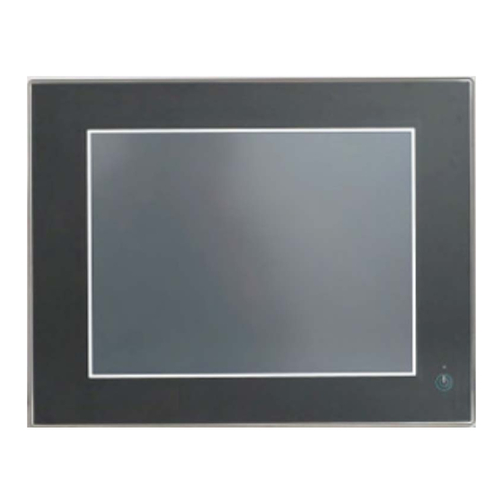
5.1 Front Side View Fig.5-13:Front view of the IP15IA99 Panel PC System (15”) Complete overlay on the front bezel of Power Button Stainless Steel or Aluminum Logo (optional) LED as Power indicator 10.4"/15"/17” TFT-LCD display with 5-Wire Touch Screen All versions are suitable for installation in an instrument panel or other cabinet. On the front side are located: ◎... -
Page 19: 10.4"/15"/17" Display With Touch Screen
5.1.1 10.4"/15"/17" Display with Touch Screen Depending on the ordered Operator Interface Computer 10"/15"/17” NEMA4 panel system, IP10IA99 / IP15IA99 / IP17IA99, the built-in display is a 10.4" or 15" or 17” display. For technical specification of the built-in display, please refer to the section of “Technical Data”... -
Page 20: Bottom View
Chemical Properties Resistant to: Alcohol Resistance surfaces withstand exposure of more than 24 hours Diluted acids duration under DIN 42 115 Part 2 to the mentioned Diluted alkalis chemicals without visible change Ester Hydrocarbon Ketones Household cleaning reagents NOTES: Please remember that information and measurements mentioned above come from general known data. These tests were done under the laboratory conditions, and don't represent an actual operation conditions. -
Page 21: Power, Control Indicators, Reset And Grounding
5.3. Power, Control Indicators, Reset and Grounding 5.3.1 Power Connector Fig.5-16: DC Power connector on the bottom (rear) side of the OIC Panel system The DC Power connector (refer to Fig.5-15, #11 and Fig.5-16) provides the power connection of the Operator Interface Computer 10"/15"/17”... -
Page 22: Fig.5-17-1: Close-Up On Front Panel Of 10"/15"/17", Power Button And Led As Power Indicator
Table 5-2: Control indicators of the system OIC (Operator Interface Computer) 10"/15"/17” NEMA4 system, IP10IA99 / IP15IA99 / IP17IA99 Power Button (on the front panel) available Power LED (on the front panel) available Power LED (on the rear bottom side) available Table 5-3: System status The system is... -
Page 23: Reset Button
outlet of the AC power source must be located near to the device and be easily accessible. 5.3.1.2 Reset Button To restart the system, e.g. after a system hang-up, press the “RESET” button (Fig.15-18). The system restarts automatically; you don’t have to switch the computer off and on. During a reset all data in the main memory will be erased. -
Page 24: Usb Connectors
5.3.2.1 USB Connectors The system is equipped at the bottom side (rear) with two USB 1.1/2.0 interface connectors and two USB1.1/2.0 for additional Extension (#1 and #5, Fig.5-19). These connectors provide connections for USB-compatible devices. 5.3.2.2 COM port Serial Interface Connector This RS232/RS422/RS485 connection (marked as COM1, COM2) (#2 and #3, Fig.5-19) are available, and RS232 connection (marked as COM3, COM4) for extensional selection as 2*5 Pin Box Header/2mm Right Angle connectors (female) and provides connection RS232 for serial devices. -
Page 25: Left And Right Side View
When powering on the Operator Interface Computer 10"/15"/17” NEMA4 system, IP10IA99 / IP15IA99 / IP17IA99, make sure that the air intake and exhaust openings are not obstructed. The Operator Interface Computer 10"/15"/17” NEMA4 system, IP10IA99 / IP15IA99 / IP17IA99, is configured with an internal 2.5"... -
Page 26: Rear View
5.6 Rear View Fig.5-25: Rear side of the system ( shown as 10.4” IP10IA99) Front panel of the system with seal at the Screws that secure the cover on the rear rear side side Mounting clamp and Allen Screw for Interface side mounting to a sub-frame Label of IPxxIA99 product designation... -
Page 27: Dc Power Cable
5.7.1 DC power cable The external AC/DC power adapter is an optional part. If ordered, the AC/DC power adapter will be delivered with two main power cords. Open Lead Cable ( 2m ) Fig.5-26: External Open Lead Cable supplied with the IPxxIA99 Panel system 5.7.2 External AC/DC Adapter The external AC/DC power adapter is an optional part. -
Page 28: Accessing Internal Components
Electrical Specifications for the AC/DC Adapter AC Input DC Output 100-240V 24V DC 1.2A 3.125A 50-60Hz For connecting to the system and power refer to “Connecting to Power”. Electrical Specifications for the Panel System System Type Product Input Operator Interface Computer IP10IA99 24V DC 1.49A max. -
Page 29: Jumpers
Fig.6-1: Top-side Jumper and Connector Locations Connector Description Remark Jumper Setting CMOS Setup JP2/J3 COM3 Pin 9 Function Setup LCD Panel Voltage Setup COM2 Pin 9 Function Setup LCD Panel Inverter ON/OFF Signal Setup Connector Compact Flash Type II Connector Case Open Detect Connector (1*2 Pin wafer/2mm) LPC Debug Card Connector (2*5Pin cut Pin 9 Header /2.54mm) GPIO Connector (2*5 Pin Header/2mm) - Page 30 COM2 (RS-232/422/485) Connector (2*5 Pin Box Header/2mm Right Angle) LCD Backlight Power Connector (1*5 Pin wafer/2mm) LCD LVDS Connector (2*15 Pin Hirose/1.25mm) Touch Panel Connector (1*5 Pin Header/2.54mm) Front Panel Connector (1*4 Pin Wafer/2mm) Power output Connector for SATA device (1*3 Pin wafer/2.5mm Right Angle) SATA Port 0 Connector (Single Right Angle) XC3S200A JTAG Connector (1*6 Pin Header/2mm) LAN1 RJ-45 Connector...
-
Page 31: Connector
JP6: LCD Panel Inverter ON/OFF Signal Setup PIN NO. DESCRIPTION Short Short +5V High Active (Default) PIN NO. DESCRIPTION Short Short +12V High Active PIN NO. DESCRIPTION Short Short +5V Low Active PIN NO. DESCRIPTION Short Short +12V Low Active JP7 &... - Page 32 J4: GPIO Connector (2*5 Pin Header/2mm) PIN NO. DESCRIPTION PIN NO. DESCRIPTION GPIO Port1 GPIO Port5 GPIO Port2 GPIO Port6 GPIO Port3 GPIO Port7 GPIO Port4 GPIO Port8 J5/J17: Power output Connector for SATA device (1*3 Pin wafer/2.5mm Right Angle) PIN NO.
- Page 33 J13: LCD Backlight Power Connector (1*5 Pin wafer/2mm) PIN NO. Description LCD_ENBLT +12V LCD_BLADJ J14: LCD LVDS Connector (2*15 Pin Hirose/1.25mm) PIN NO. Description PIN NO. Description YAP0 YAM0 YAP1 YAM1 YAP2 YAM2 YAP3 YAM3 CLKAP CLKAM YBP0 YBM0 YBP1 YBM1 YBP2 YBM2...
- Page 34 J19: XC3S200A JTAG Connector (1*6 Pin Header/2mm) PIN NO. DESCRIPTION +3.3V J20: LAN1 RJ-45 Connector J21: LAN2 RJ-45 Connector J22: USB Port 0~1 Connector (Type A) J23: COM1 (RS-232/422/485) Connector (D-SUB9) J24: VGA Connector (D-SUB 15 Pin female) J25: Power Input Connector (Terminal Blocks 5Px1/3.81mm female) PIN NO.
-
Page 35: Memory Module Installation
6.1.3 Insert Memory module The Operator Interface Computer 10"/15"/17” NEMA4 system, IP10IA99 / IP15IA99 / IP17IA99, is fully integrated at system assembly line before shipment. It’s not necessary for end users to do any assembly unless installing the optional HDD, RAM, CF and Power Input. Installation of these optional components is described below. 1. -
Page 36: Serial Ata Hard Disk Installation
6.1.4 Serial ATA Hard Disk Installation Method Unlike IDE bus, each Serial ATA (SATA) channel can only connect to one SATA hard disk at a time; there are total two connectors, J6 and J18. The installation of Serial ATA is simpler and easier than IDE, because SATA hard disk doesn’t require setting up Master and Slave, which can reduce mistake of hardware installation. -
Page 37: Cf Card Installation
6.1.5 CF Card Installation 1. Unscrew the side bracket of back cover 2. Remove the side bracket 3. Insert New CF card to CF socket carefully 4. Insert New CF card to CF socket carefully 5. Complete insertion (Ejection by pressing the 6. -
Page 38: Dc Power Input Installation
6.1.6 DC Power Input Installation 6.1.6.1 AC/DC Power adaptor installation 1. Female type 5-pin terminal block connector. 2. Insert and fix the connector according to power definition (left 3-pin) Fig.6-5 : Power adaptor installation 6.2 Panel and External AC/DC Adapter Mounting 6.2.1 Panel Mounting All Operator Interface Computer 10"/15"/17”... -
Page 39: Fig.6-7: Panel Cut-Out Dimension For Ip10Ia99
Fig.6-7: Panel cut-out dimension for IP10IA99 Fig.6-8: Panel cut-out dimension for IP15IA99 Page 38 OIC Panel 10”/15”/17” - User Manual (Ver.1.02) -
Page 40: Fig.6-9: Panel Cut-Out Dimension For Ip17Ia99
Fig.6-9: Panel cut-out dimension for IP17IA99 Page 39 OIC Panel 10”/15”/17” - User Manual (Ver.1.02) -
Page 41: Fig.6-10: Mounting Kit Step By Step
Table 6-1: Cut-out Dimension by Panel size. (mm) Mounting Kits IP10IA99 46.0 297.0 236.0 IP15IA99 49.4 408.5 313.0 IP17IA99 10.0 52.4 422.0 360.0 Hook Clip Screw the Clip tightly (Spec<=1.35 N ) Hook the mounting clamps with screws (included) from the rear side of the panel Fig.6-10 : Mounting kit step by step In order to ensure NEMA 4 front sealing against dust and water, mount the system on a non-textured surface. -
Page 42: Vesa Mounting
6.2.2 VESA® Mounting Plate (Optional) The OIC (Operator Interface Computer) 10"/15"/17” NEMA4 system, IP10IA99 / IP15IA99 / IP17IA99, can be installed with the provided (as optional part) VESA® 75/100 compliant adapter plate (refer to #4, Fig.5-25). Each VESA® 75/100 compliant mounting plate must be fasten to the Operator Interface Computer 10"/15"/17” NEMA4 system, IP10IA99 / IP15IA99 / IP17IA99, with four M4 x 4 metric screws (included). -
Page 43: Getting Started
in the housing for the AC/DC adapter) Threaded holes for securing the housing 4x mounting holes for the DIN Rails clip that with AC/DC adapter to the wall mount plate allow the clip mounting Latch with captive screws, slotted flat head DIN Rail clip for securing the housing with AC/DC adapter to the wall mount plate... - Page 44 1. Connect the 5-pin DC power connector of the DC power cable (refer to Fig.5-26) to the appropriate DC power connector (refer to #12, Fig.5-15) of the Operator Interface Computer 10"/15"/17” NEMA4 system, IP10IA99 / IP15IA99 / IP17IA99. The DC power connector of the system is on the rear bottom side and is labeled “12V/24V (+/-20%) DC”.
-
Page 45: Connecting To Ac Power Source Via The Ac/Dc Adapter
6.3.2 Connecting to AC Power Source via the AC/DC Adapter The Operator Interface Computer 10"/15"/17” NEMA4 system, IP10IA99 / IP15IA99 / IP17IA99, can be optionally connected to an AC power source via the optional AC/DC adapter (refer to Fig.5-27). Fig.6-16 : Connecting to AC power source via the AC/DC adapter 1. -
Page 46: Bios Setup
6.4 BIOS Setup Operator Interface Computer 10"/15"/17” NEMA4 system, IP10IA99 / IP15IA99 / IP17IA99 is equipped with the AMI BIOS stored in Flash ROM. These BIOS has a built-in Setup program that allows users to modify the basic system configuration easily. This type of information is stored in CMOS RAM so that it is retained during power-off periods. When system is turned on, the built-in Main board communicates with peripheral devices and checks its hardware resources against the configuration information stored in the CMOS memory. -
Page 47: Information
AMI BIOS, CPU, System Memory These items show the firmware and hardware specifications of your system. Read only. System Date The date format is <Day>, <Month> <Date> <Year>. Use [+] or [-] to configure system Date. System Time The time format is <Hour> <Minute> <Second>. Use [+] or [-] to configure system Time. 6.4.3 Information Use this menu for basic system configurations, such as system information, product feature and technical important issue etc. -
Page 48: Configuration
6.4.4 Configuration Use this menu to set up the items of special enhanced features. Fig.6-19:Setup Program Initial Screen ACPI Settings Select for Advanced ACPI Configuration. This item specifies the power saving modes for ACPI function. If your operating system supports ACPI, you can choose to enter the Standby mode in S1 (POS) or S3 (STR) fashion through the setting of this field. -
Page 49: Fig.6-20: Acpi Configuration
Fig.6-20:ACPI Configuration CPU Configuration These items show the advanced specifications of your CPU. Read only. Fig.6-21:CPU Configuration Page 48 OIC Panel 10”/15”/17” - User Manual (Ver.1.02) - Page 50 Intel(R) Speed Step (tm) Disable: Disable. Enable: Enable. (Default) Hyper Threading Technology “Enabled” for Windows XP and Linux (OS optimized for Hyper-Threading Technology) and “Disabled” for other OS (OS not optimized for Hyper-Threading Technology). The choice: Enabled (Default), Disabled. Execute-Disable Bit capability XD can prevent classes of malicious buffer overflow attacks when combined with a supporting OS.
-
Page 51: Fig.6-22: Usb Configuration
Fig.6-22:USB Configuration SATA Configuration It uses a separate sub menu to configure each hard disk drive. Fig.6-23:SATA Configuration ATA/IDE Configuration The choice: Disabled, Compatible, Enhanced (Default). Page 50 OIC Panel 10”/15”/17” - User Manual (Ver.1.02) - Page 52 Legacy IDE Channels The choice: IDE Only (Default). Integrated Video Configuration Share memory size This option determines the amount of system memory that can be used by the internal graphics device. Disable Enable, 1MB of memory used by internal graphics device Enable, 8MB of memory used by internal graphics device (Default) DVMT Mode Select Use this option to select the Intel Dynamic Video Memory Technology (DVMT) operating mode.
-
Page 53: Fig.6-24: Integrated Video Configuration
Level 5 is max. LED backlight brightness Active LVDS Use this option to select the Active LFP configuration No-LVDS: VBIOS does not enable LVDS. Int-LVDS: VBIOS enables LVDS driver by integrated encoder. (Default) Fig.6-24:Integrated Video Configuration Fig.6-25:GMCH BLC Control Page 52 OIC Panel 10”/15”/17”... -
Page 54: Fig.6-26: Lan Configuration
LAN Configuration Launch PXE OpROM Use this option to select Enabled or Disabled (Default) option for Legacy Network Devices. LAN Wake Up This field specifies whether the system will be awakened from the S5 .power saving mode when activity or input signal of onboard LAN is detected. -
Page 55: Fig.6-27: W83627Uhg Serial Port 1 Configuration
Fig.6-27:W83627UHG Serial Port 1 Configuration WDT Function. Select WDT Function is Enabled or Disabled (Default) Fig.6-28:W83627UHG Super IO Configuration Page 54 OIC Panel 10”/15”/17” - User Manual (Ver.1.02) -
Page 56: Fig.6-29: H/W Monitor Configuration
H/W Monitor This function is real-time detecting system status, CPU temperture, System temperture, relational Volts (12V, 3.3V) Fig.6-29:H/W Monitor Configuration Serial Port Console Redirection Configuration Console Redirection Use this option to specify when console redirection should occur: Disabled the console is not re-directed after POST (Default) Enabled Redirection is active during POST and during Boot Loader Page 55... -
Page 57: Fig.6-30: Serial Port Console Redirection Configuration
Fig.6-30:Serial Port Console Redirection Configuration PCI Configuration PCI BUS Driver Version V2.03.00 PCI ROM Priority In this system with Multiple option ROMs The Choice:Legacy ROM and EPI Compatible ROM (Default) Launch Storage OpROM Enabled (Default) or Disable Boot Option for Legacy Mass Strorage Devive with Option ROM PCI Latency Timer Select value in units of PCI clocks for PCI device latency timer register. -
Page 58: Fig.6-31: 15 Pci Configuration
Fig.6-31:15 PCI Configuration Power Control Configuration Wake system with Fixed Time Enabled or Disabled (Default) System wake on alarm event. When enabled System will wake on the hr:min:sec. specified. Wake system with Dynamic Time Enabled or disabled (Default) System wake on alarm event. When system enabled will wake on the current time + Increase minute(s). -
Page 59: Fig.6-32: Power Control Configuration
Fig.6-32:Power Control Configuration Wake up by Ring Use this option to enable activity on the RI (ring in) modem line to rouse the system from a suspend or standby state. That is, the system will be roused by an incoming call on a modem. Disabled:Wake event not generated by an incoming call (Default) Enabled:Wake event generated by an incoming call Advanced Configuration... -
Page 60: Boot
Fig.6-33:Advanced Configuration 6.4.5 Boot Quiet Boot Use this option to select the screen display when the system boots. Disabled Normal POST messages displayed (Default) Enabled OEM Logo displayed instead of POST messages Fast Boot Use this option to make the computer speed up the boot process. Disabled No POST procedures are skipped (Default) Enabled Some POST procedures are skipped to decrease the system boot time Boot Option#1... -
Page 61: Security
Fig.6-34:Boot 6.4.6 Security Use the Security option to set Administrator and user passwords. If only the administrator’s password is set, then this only limits access to Setup and is only asked for when entering Setup. If only the user’s password is set, then this is power on password and must be entered to boot or enter Setup .In setup the user will have Administrator rights. -
Page 62: Save And Exit
Fig.6-35:Security 6.4.7 Save and Exit Save Changes and Exit Exit System Setup after saving the changes. Discard Changes and Exit Exit System Setup without saving any changes. Save Changes and Reset Reset the system after saving the changes. Discard Changes and Reset Reset system setup without any saving any changes. -
Page 63: Software Installation
Restore as User Default Restore the User defaults to all the Setup Option. Boot Override SATA: HDD (Default) Launch EFI Shell from fileSystem Attempts to Launch EFI Shell application (Shellx64.efi) from one of the available file System devices. Fig.6-36:Save and Exit 6.5. - Page 64 Computer Panel system before shipment. Run the calibration routine when an alignment problem exists between the mouse pointer and the stylus contact location on the screen. You can adjust the calibration of the touch screen by: The calibration procedure is shown by degrees. In the first, From the [Program] to find [eGalaxTouch] icon then click the [Configure Utility].
- Page 65 Click [Draw Test], draw by touch pen or finger to know touch accuracy Click the Page [Display]; you can select the Click the Page [Hardware], Controller Model and Operation Mode. Firmware Version can be seen. Click [Hardware Setting], you can adjust Sensitivity Click the Page [Edge Compensation] to adjust the Edge and Delay time of touch screen Parameters.
-
Page 66: Brightness Control
Fig.6-37:Touch calibration procedure The front panel and the touch screen are covered by a plastic overlay and care should be taken when cleaning it. 6.5.2 Brightness Control The “Brightness Control” icon on the notification bar shown below provides selection to adjust the brightness of the Operator Interface Computer 10"/15"/17”... -
Page 67: Fig.6-38: Brightness Control Procedure
2. Click the “Brightness Control” icon in the 3. Move the slide bar in the “Brightness Control” notification area. window to adjust the brightness. Fig.6-38:Brightness Control procedure Page 66 OIC Panel 10”/15”/17” - User Manual (Ver.1.02) -
Page 68: Technical Data
7. Technical Data 7.1. Product Specification IP10IA99 Panel PC IP15IA99 Panel PC IP17IA99 Panel PC Feature Specification Description Specification Description Specification Description Model IP10IA99-A1 10.4” Industrial Fan-free Panel PC IP15IA99-A1 15” Industrial Fan-free Panel PC IP17IA99-A1 17” Industrial Fan-free Panel PC Intel®... - Page 69 I/O (Extension) - 2 x USB 1.1/2.0 ports (Default) - 1 x RS-232 port (COM3) + 2x USB 1.1/2.0 ports, (Default) - 1 x RS-232 port (COM3) + 2x USB 1.1/2.0 ports, (Default) for Additional - 1x RS-232 port (COM3), (Optional) - 2 x RS-232 port (COM3, 4) (Optional) - 2 x RS-232 port (COM3, 4) (Optional) - 4x USB 1.1/2.0 ports (Optional)
- Page 70 IP Rating IP65 / NEMA 4 IP65 / NEMA 4 IP65 / NEMA 4 Whole enclosure: IPX1 ( IEC 60529 Edition 2.1 Standard) Whole enclosure: IPX1 (IEC 60529 Edition 2.1 Standard) Whole enclosure: IPX1 ( IEC 60529 Edition 2.1 Standard) Front Bezel Flat Front Bezel + Overlay Complete Design Flat Front Bezel + Complete Overlay Design...
-
Page 71: Mechanical Specifications
7.2 Mechanical Specifications Fig.7-1:Front view of 10.4“ Panel PC system Fig.7-2:Front view of 15“ Panel PC system Page 70 OIC Panel 10”/15”/17” - User Manual (Ver.1.02) -
Page 72: Fig.7-3: Front View Of 17"Panel Pc System
Fig.7-3:Front view of 17“ Panel PC system Page 71 OIC Panel 10”/15”/17” - User Manual (Ver.1.02) -
Page 73: Fig.7-4: Rear & Right-Side View Of 10.4" Panel Pc System
Fig.7-4-1: Rear view of 10.4” Panel PC System Fig.7-4-2:Right-side view of 10.4” Panel PC System Fig.7-5-1:Rear view of 15” Panel PC System Fig.7-5-2:Right-side view of 15” Panel PC System Page 72 OIC Panel 10”/15”/17” - User Manual (Ver.1.02) -
Page 74: Fig.7-6: Rear & Right-Side View Of 17" Panel Pc System
Fig.7-6-1:Rear view of 17” Panel PC System Fig.7-6-2:Right-side view of 17” Panel PC System Fig.7-7-1: Wall mount kit Top View Fig.7-7-2 : Wall mount kit Side view Page 73 OIC Panel 10”/15”/17” - User Manual (Ver.1.02) -
Page 75: Certifications And Standards
7.3. Certifications and Standards Standards, Certificates and Approvals Description Details UL approval UL60950-1 2006/95/EC Low voltage directive EMC directive 2004/108/EC Requirements for emission EN 61000-6-4 :2007 EN 61000-6-2 :2005 Requirements for interference immunity FCC Part 15, Subpart B, Class A Standards for EMC &... -
Page 76: Rma (Return Material Authorization) Service
Authorization (RMA). 4. Make sure to receive an RMA number from AIS before returning any merchandise. Clearly write or mark this number on the outside of the package you are returning. Any returns without an authorization will be refused and returned to you by the shipper. - Page 77 Subject to change without 1-888-485-6688 prior notice. Any product names mentioned may be trademarks or product www.aispro.com designations of AIS or its suppliers, whose use by third parties for their own purposes may infringe the rights of the trademark owners.
Need help?
Do you have a question about the IP10IA99 series and is the answer not in the manual?
Questions and answers