Canon iR2020 Series Service Manual
Hide thumbs
Also See for iR2020 Series:
- Service manual (406 pages) ,
- Facsimile manual (232 pages) ,
- Copying manual (124 pages)
Table of Contents
Advertisement
Quick Links
Advertisement
Table of Contents

Related Manuals for Canon iR2020 Series


Summary of Contents for Canon iR2020 Series
- Page 1 Service Manual iR2020/2016 Series Oct 3 2005...
- Page 3 Canon will release technical information as the need arises. In the event of major changes in the contents of this manual over a long or short period, Canon will issue a new edition of this manual.
- Page 4 Introduction Symbols Used This documentation uses the following symbols to indicate special information: Symbol Description Indicates an item of a non-specific nature, possibly classified as Note, Caution, or Warning. Indicates an item requiring care to avoid electric shocks. Indicates an item requiring care to avoid combustion (fire). Indicates an item prohibiting disassembly to avoid electric shocks or problems.
- Page 5 Introduction The following rules apply throughout this Service Manual: 1. Each chapter contains sections explaining the purpose of specific functions and the relationship between electrical and mechanical systems with refer- ence to the timing of operation. In the diagrams, represents the path of mechanical drive; where a signal name accompanies the symbol , the arrow indicates the direction of the electric signal.
-
Page 7: Table Of Contents
Chapter 1 Introduction 1.1 System Construction ............................1- 1 1.1.1 Pickup/ Delivery /Original Handling Accessories System Configuration (iR2020/iR2020J) ..1- 1 1.1.2 Pickup/ Delivery /Original Handling Accessories System Configuration (iR2016/iR2016J) ..1- 2 1.1.3 Reader Heater/ Cassette Heater System Configuration ..............1- 3 1.1.4 Printing/Transmitting Accessories System Configuration (iR2020J/iR2016J) ....... - Page 8 Contents Chapter 2 Installation 2.1 Making Pre-Checks ............................2- 1 2.1.1 Selecting the Site of Installation......................2- 1 2.1.2 Before Starting the Work (230V EUR) ....................2- 1 2.2 Unpacking and Installation ..........................2- 3 2.2.1 Unpacking and Removing the Packaging Materials................2- 3 2.2.2 Installing the Drum Unit...........................
- Page 9 Contents 3.4 Flow of Image Data ............................3- 5 3.4.1 Flow of Image Data According to Copy Functions ................3- 5 3.4.2 Flow of Image Data for the SEND Function ..................3- 6 3.4.3 Flow of Image Data for the Fax Transmission ..................3- 6 3.4.4 Flow of Image Data for the Fax Reception Function................
- Page 10 Contents 4.3.6.1 Outline............................... 4- 11 4.3.6.2 CMOS Sensor Drive ........................4- 12 4.3.6.3 CMOS Sensor Output Gain Correction and Offset Correction ..........4- 13 4.3.6.4 CMOS Sensor Output A/D Conversion ..................4- 13 4.3.6.5 Shading Correction (Outline) ......................4- 13 4.3.6.6 Shading Adjustment........................
- Page 11 Contents 4.4.7.3 Removing the Original Sensor (Horizontal Scan Direction)............. 4- 24 4.4.8 Reader Heater (option).......................... 4- 24 4.4.8.1 Removing the Copyboard glass ....................4- 24 4.4.8.2 Removing the Reader Heater (Right) ..................4- 25 4.4.8.3 Removing the Reader Front Cover ....................4- 25 4.4.8.4 Removing the ADF Reading Glass ....................
- Page 12 Contents 6.5.2 Charging Mechanism ..........................6- 4 6.5.2.1 Primary Charging Bias Control ....................... 6- 4 6.6 Developing Unit ............................... 6- 5 6.6.1 Outline................................ 6- 5 6.6.2 Developing Bias Control ......................... 6- 5 6.7 Toner Container .............................. 6- 6 6.7.1 Outline................................ 6- 6 6.8 Transfer Unit ..............................
- Page 13 Contents 7.2.2 Stationary Jams ............................7- 6 7.2.2.1 Stationary Jam in Pickup Assembly....................7- 6 7.2.2.2 Stationary Jam in Delivery Assembly (Paper Trailing Edge Stationary Jam at Delivery Sensor/ Stationary Jam at Delivery Sensor) ....................... 7- 6 7.2.3 Other Jams ..............................7- 6 7.2.3.1 Door Open Jam..........................
- Page 14 Contents 7.5.11.1 Removing the Feed and Separation Rollers................7- 15 7.5.12 Separation Pad ............................. 7- 15 7.5.12.1 Removing the Drum Unit......................7- 15 7.5.12.2 Removing the Transfer Registration Unit .................. 7- 15 7.5.12.3 Removing the Feed Guide......................7- 15 7.5.12.4 Removing the Multifeeder Pickup Roller ................... 7- 15 7.5.12.5 Removing the Separation Pad ....................
- Page 15 Contents 8.4.4.3 Removing the Left Cover (Rear) ....................8- 17 8.4.4.4 Removing the Left Door......................... 8- 17 8.4.4.5 Removing the Fixing Unit ......................8- 18 8.4.4.6 Removing the Fixing Delivery Sensor ..................8- 18 8.4.5 Fixing Film Sensor ..........................8- 19 8.4.5.1 Removing the Drum Unit .......................
- Page 16 Contents 9.4.4 Control Panel............................9- 10 9.4.4.1 Removing the Reader Front Cover ....................9- 10 9.4.4.2 Removing the Operation Panel Unit .................... 9- 11 9.4.5 DC Controller PCB ..........................9- 11 9.4.5.1 Removing the Rear Cover ......................9- 11 9.4.5.2 Removing the DC Controller PCB ....................9- 11 9.4.6 Option Power Supply PCB ........................
- Page 17 Contents 10.2.3 Printer Unit ............................10- 1 10.3 Scheduled Servicing Basic Procedure ....................10- 2 10.3.1 Scheduled Servicing..........................10- 2 Chapter 11 Standards and Adjustments 11.1 Scanning System............................11- 1 11.1.1 Procedure after Replacing the CIS ....................11- 1 11.2 Image Formation System .......................... 11- 1 11.2.1 Procedure after Replacing the Developing Assembly ..............
- Page 18 Contents 13.4.1 Error Code Details ..........................13- 4 13.5 FAX Error Codes............................13- 8 13.5.1 Outline ..............................13- 8 13.5.1.1 Error Code Outline ........................13- 8 13.5.2 User Error Code............................ 13- 8 13.5.2.1 User Error Code ..........................13- 8 13.5.3 Service Error Code ..........................13- 8 13.5.3.1 Service Error Code ........................
- Page 19 Contents 14.3.9.4 Detailed Discussions of Bit 2 ....................14- 10 14.3.9.5 Detailed Discussions of Bit 3 ....................14- 10 14.3.9.6 Detailed Discussions of Bit 4 ....................14- 10 14.3.9.7 Detailed Discussions of Bit 5 ....................14- 10 14.3.10 SSSW-SW30............................. 14- 11 14.3.10.1 List of Functions ........................
- Page 20 Contents 14.6.5 <031Vertical scan start position adjustment>................14- 19 14.6.6 <032Horizontal scan start position adjustment> ................14- 19 14.6.7 <033Vertical scan magnification correction>................. 14- 19 14.6.8 <035: - 036:Reader motor speed change>..................14- 19 14.6.9 <041: Vertical scan start position adjustment (when scanning on a document fed from ADF)> 14- 14.6.10 <042: Horizontal scan start position adjustment (when scanning on a document fed from ADF)>...
- Page 21 Contents 14.8.1 Bit Switch Settings ..........................14- 24 14.9 Registration of Accessories (ACC) ......................14- 24 14.9.1 Accessory Registration ........................14- 24 14.10 Display of Counter Information (COUNTER) ..................14- 25 14.10.1 Counters............................14- 25 14.10.2 Clearing Counters..........................14- 25 14.11 Service Report (REPORT) ........................
-
Page 23: Chapter 1 Introduction
Chapter 1 Introduction... - Page 25 Contents Contents 1.1 System Construction............................1-1 1.1.1 Pickup/ Delivery /Original Handling Accessories System Configuration (iR2020/iR2020J) ....1-1 1.1.2 Pickup/ Delivery /Original Handling Accessories System Configuration (iR2016/iR2016J) ....1-2 1.1.3 Reader Heater/ Cassette Heater System Configuration................1-3 1.1.4 Printing/Transmitting Accessories System Configuration (iR2020J/iR2016J)........... 1-3 1.1.5 Printing/Transmitting Accessories System Configuration (iR2020/iR2016)..........
-
Page 27: System Construction
*1: This accessory comes standard with the models for Asia excluding Taiwan and the models for some Latin American countries. *2: This accessory is required when the Finisher-U1, Inner 2-way tray-E1, Cassette feeding module-K1, or Duplex unit-A1 is installed. This accessary comes standard with the iR2020 for North America, Latin America, and Asia. -
Page 28: Pickup/ Delivery /Original Handling Accessories System Configuration (Ir2016/Ir2016J)
Chapter 1 1.1.2 Pickup/ Delivery /Original Handling Accessories System Configuration (iR2016/iR2016J) 0011-0892 iR2016J / iR2016 The configuration is as shown in the following figure: [10] [11] F-1-2 DADF-P1 Platen Cover Type J Finisher-U1 Additional Finisher Tray-C1 Inner 2-way Tray-E1 Cassette Feeding Module-J1 Cassette Feeding Module-K1 Duplex Unit-A1 Power Supply Kit-Q1... -
Page 29: Reader Heater/ Cassette Heater System Configuration
Chapter 1 1.1.3 Reader Heater/ Cassette Heater System Configuration 0011-0901 iR2016J / iR2016 / iR2020 / The configuration is as shown in the following figure: F-1-3 Reader Heater Cassette Heater Heater PCB *1: To operate the heaters, a heater PCB is required. -
Page 30: Printing/Transmitting Accessories System Configuration (Ir2020/Ir2016)
256MB Expansion RAM-D1 *1: To make the FAX feature effective, a FAX panel and a super G3 FAX board are required. *2: The PCL printer kit contains a 256MB expansion RAM. 1.1.6 Functions of the Printing/Transmission Functions (iR2020/iR2016) 0011-1092 iR2016 / iR2020 The following is a brief explanation of the functions expected of the accessories;... -
Page 31: Product Specifications
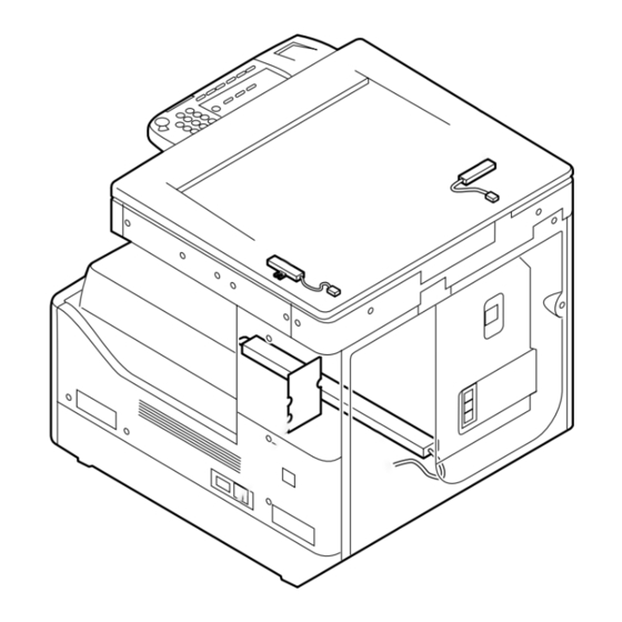
Chapter 1 1.2 Product Specifications 1.2.1 Names of Parts 1.2.1.1 External View ÅiiR2020/iR2020J) 0011-1098 iR2020 / [14] [13] [12] [11] [15] [10] [16] [18] [17] F-1-5 Copyboard cover (*1) [10] Left door Reader front cover [11] Left cover (rear) Control panel... -
Page 32: External View Åiir2016/Ir2016J)
Chapter 1 1.2.1.2 External View ÅiiR2016/iR2016J) 0011-1099 iR2016J / iR2016 [13] [12] [11] [10] [14] [16] [15] F-1-6 Copyboard cover (*1) Left door Reader front cover [10] Left cover (rear) Control panel [11] Reader left cover Delivery tray [12] Reader right cover Front cover [13] Reader erar cover... -
Page 33: Cross-Section
Chapter 1 1.2.1.3 Cross-Section 0010-8574 iR2016J / iR2016 / iR2020 / / iR2016i / iR2020i [18] [17] [16] [15] [14] [13] [12] [11] [10] [9] [8] [7] F-1-7 CIS unit [10] Separation roller Reader unit [11] Vertical path roller Laser scanner unit... -
Page 34: Using The Machine
1.2.2.1 Turning On the Power Switch 0011-1100 iR2016J / iR2016 / iR2020 / / iR2016i / iR2020i The machine possesses 2 power switches: main power switch and control power switch. Normally (i.e., unless the machine is in a sleep state), the machine will be supplied with power when you turn on its main power switch. -
Page 35: When Turning Off The Main Power Switch
1.2.2.2 When Turning Off the Main Power Switch 0011-1101 iR2016J / iR2016 / iR2020 / / iR2016i / iR2020i <During printing or fax data transmission/reception> Be sure to operate the main power switch while the Processing/Data lamp on the control panel is not lit. -
Page 36: Control Panel
Chapter 1 1.2.2.3 Control Panel 0011-1103 iR2016J / iR2016 / iR2020 / [10] [11] [12] [13] [14] [15] [31] [29] [27] [25] [23] [21] [19] [17] [30] [28] [26] [24] [22] [20] [18] [16] F-1-11 Paper select key [17] ID key... -
Page 37: User Mode Items
Chapter 1 1.2.3 User Mode Items 1.2.3.1 Common Settings 0011-1222 iR2016J / iR2016 / iR2020 / / iR2016i / iR2020i Additional Functions Available Settings 1. DEFAULT SETTINGS COPY(*), FAX 2. AUTO CLEAR SET. INITIAL FUNCTION(*), SELECTED FUNCTION 3. AUDIBLE TONES... -
Page 38: Address Book Set
CONT. PRINTING: RX TO MEMORY(*), KEEP PRINTING *: Factory default 1.2.3.4 Address Book Set. 0011-1225 iR2016J / iR2016 / iR2020 / / iR2016i / iR2020i Additional Functions Available Settings 1. 1-TOUCH SPD DIAL Up to 60 destinations can be registered: TEL NUMBER ENTRY, NAME, OPTIONAL SETTING 2. -
Page 39: Timer Settings
Chapter 1 *: Factory default 1.2.3.6 Timer Settings 0011-1227 iR2016J / iR2016 / iR2020 / / iR2016i / iR2020i Additional Functions Available Settings 1. DATE&TIME SETTING Default setting 2. DATE TYPE SELECT DD/MM YYYY(*), YYYY MM/DD, MM/DD/ YYYY 3. AUTO SLEEP TIME ON (3 - 30 (5(*)) MIN. - Page 40 Chapter 1 Additional Functions Available Settings 6. COMMUNICATIONS TX START SPEED: 2400 to 33600(*) bps RX START SPEED: 2400 to 33600(*) bps MEMORY LOCK SETTI: OFF(*), ON (PASSWORD, REPORT PRINT, MEMORY RX TIME) R-KEY SETTING: PSTN(*), PBX (HOOKING, PREFIX) 7. REMOTE UI ON(*), OFF 8.
-
Page 41: Maintenance By The User
Chapter 1 1.2.4 Maintenance by the User 1.2.4.1 User Maintenance Items 0011-2393 iR2016J / iR2016 / iR2020 / / iR2016i / iR2020i T-1-1 Item Maintenance cycle Remarks Pressure plate cleaning As required opyboard glass(large/small) cleaning As required Copyboard holder (jump board) -
Page 42: Safety
0010-8951 iR2016J / iR2016 / iR2020 / / iR2016i / iR2020i Laser light can prove to be hazardous to the human body. The machine's laser unit is fully enclosed in a protective housing and external covers so that its light will not escape outside as long as the machine is used normally. -
Page 43: Handling The Laser Unit
1.2.5.3 Handling the Laser Unit 0010-8955 iR2016J / iR2016 / iR2020 / / iR2016i / iR2020i The laser scanner unit emits invisible laser light inside it. If exposed to laser light, the human eye can irreparably be damaged. Never attempt to disassemble the laser scanner unit. -
Page 44: Point To Note About Fire
1.2.5.5 Point to Note about Fire 0010-7304 iR2016J / iR2016 / iR2020 / / iR2016i / iR2020i It is dangerous to throw lithium batteries and parts and components containing flammable substances, such as cartridges, etc., into fire. Such parts and components must be disposed of in accordance with local laws and regulations. -
Page 45: Product Specifications
22 Wh (reference only) / continuous printing: 500 Wh (reference only) Ozone max.: 0.02 ppm or less Dimensions iR2020 series: 622 mm x 633.4 mm x 665.4 mm (WxDxH) iR2016 series: 622 mm x 633.4 mm x 580.4 mm (WxDxH) 1-19... -
Page 46: Function List
Chapter 1 Weight iR2020 series: approx. 46 kg iR2016 series: approx. 39.6 kg 1.2.7 Function List 1.2.7.1 Printing Speed (iR2020/iR2020J) 0011-1093 iR2020 / T-1-2 Paper size Single-sided Casette feed Manual feed Plain paper STMT STMTR LTRR Heavy paper 1/2 12(10) -
Page 47: Printing Speed (Ir2016/Ir2016J)
- The copy speed may become down when the copies make continuously one minutes or more with the narrow width paper. The slowdown is reduced with the following user mode. User Mode: Additional Functions > Adjust/Cleaning > Spesial Mode P > ON 1.2.7.3 Types of Paper 0011-1097 iR2016J / iR2016 / iR2020 / / iR2016i / iR2020i 1-21... - Page 48 Chapter 1 T-1-4 Source Type Paper size Manual Feed Tray Cassette Plain paper, eco paper, recycled paper A3, B4, A4, A4R, B5, B5R, A5, LDR, (64-90g/m2) LGL, LTR, LTRR, STMT, 8K, 16K Special paper Heavy paper Width: 95mm-297mm (90-128g/m2) Length: 148mm-432mm A4, LTR Postcard Postcard A6R modified...
- Page 49 Chapter 1 1-23...
-
Page 51: Chapter 2 Installation
Chapter 2 Installation... - Page 53 Contents Contents 2.1 Making Pre-Checks ............................2-1 2.1.1 Selecting the Site of Installation........................2-1 2.1.2 Before Starting the Work (230V EUR) ....................... 2-1 2.2 Unpacking and Installation..........................2-3 2.2.1 Unpacking and Removing the Packaging Materials ................... 2-3 2.2.2 Installing the Drum Unit..........................2-3 2.2.3 Installing the Toner Bottle...........................
-
Page 55: Making Pre-Checks
2.1.1 Selecting the Site of Installation 0011-1068 iR2016J / iR2016 / iR2020 / / iR2016i / iR2020i Select the site of installation against the following requirements; if possible, visit the user's before delivery of the machine: 1) There must be a power outlet properly grounded and rated as indicated (-/+10%) for exclusive use by the machine. - Page 56 Black toner ---1 Caution sheet ---2(1) (*1) Power cable ---1 *1: iR2020: 2 pc., iR2016/iR2016J: 1 pc. Check the documentation and CD against the following table: T-2-1 Documentation and CD iR2020/iR2016 iR2016J Operators manual: User's Guide Operators manual: Easy Operation Guide...
-
Page 57: Unpacking And Installation
2.2.1 Unpacking and Removing the Packaging Materials 0011-1070 iR2016J / iR2016 / iR2020 / / iR2016i / iR2020i 1) Unpack the machine and remove vinyl, cushioning materials, and tape. 2) Hold the handles [1] of the machine together with one or more persons and take it out. -
Page 58: Installing The Toner Bottle
2.2.3 Installing the Toner Bottle 0011-1072 iR2016J / iR2016 / iR2020 / / iR2016i / iR2020i If the machine is installed in a low-temperature, low-humidity place, the im- age density may be slightly lower than usual on the first approx. 100 sheets printed after installation of the machine. -
Page 59: Setting The Cassettes
Install, the toner cartridge following the above-mentioned procedure. 2.2.4 Setting the Cassettes 0011-1073 iR2016J / iR2016 / iR2020 / / iR2016i / iR2020i 1) Holding the knob [1] at the center of the cassette, draw out the cassette [2] until it stops. -
Page 60: Attaching The Ferrite Core
8) Affix the caution sheet printed in an appropriate language. F-2-30 2.2.6 Checking the Image Quality 0011-1075 iR2016J / iR2016 / iR2020 / / iR2016i / iR2020i 1) Plug the power cord into the outlet, and then turn on the main power... -
Page 61: Setting The Country/Region
2.2.7 Setting the Country/Region 0011-1077 iR2016J / iR2016 / iR2020 / / iR2016i / iR2020i 1) Press the following keys to display the service mode screen: Additional Functions Key > 2 Key > 8 Key > Additional Functions Key 2) Select "# CLEAR"... -
Page 62: Checking The Connection To The Network
2.3 Checking the Connection to the Network 2.3.1 Checking the Network Connection 0011-1079 iR2016 / iR2020 / iR2016i / iR2020i If the machine supports a network feature, check the network connection following the procedure below. 1) Press the following keys to display the service mode screen: Additional Functions Key >... -
Page 63: Installing The Card Reader
Chapter 2 2.4 Installing the Card Reader 2.4.1 Points to Note 0011-1080 iR2016J / iR2016 / iR2020 / / iR2016i / iR2020i When installing the card reader, the card reader attachment-D1 is required. 2.4.2 Checking the Contents 0011-1081 iR2016J / iR2016 / iR2020 / / iR2016i / iR2020i <Card reader-E1>... -
Page 64: Installation Procedure
4 pcs. 2.4.3 Installation Procedure 0011-1082 iR2016J / iR2016 / iR2020 / / iR2016i / iR2020i 1) Turn off the main power switch [1] of the host machine and disconnect the power plug [2] from the outlet. F-2-34 2) Remove the four screws, and then detach the rear cover [1]. - Page 65 Chapter 2 F-2-37 When removing the harness [1] through the opening in the card reader mount, take care not to cut or damage it. F-2-38 MEMO: The removed card reader mount is no longer necessary. 5) Insert the card reader [2] harness and ground cable into the hole in the supplied card reader mount [1]. Using the screw [3] removed in step 1, secure the card reader to the card reader mount.
- Page 66 Chapter 2 F-2-40 7) Connect the connector [1] of the supplied repeating harness B to the connector [2] on the card reader. Using the supplied binding screw (M4x6), secure the repeating harness B clamp [4]. Disconnect the shorting connector [5]. If the shorting connector [5] is not disconnected, a malfunction or error can result.
- Page 67 Chapter 2 F-2-43 10) Using the two supplied TP screws (M4x16), attach the card reader to the reader. When tightening the screws, take care not to damage the repeating harness B. F-2-44 11) Slide the card reader cover [1] to attach it to the card reader mount. F-2-45 Route the repeating wire B [1] as shown below.
- Page 68 Chapter 2 F-2-47 13) Affix the two supplied harness covers (bases) at the right rear of the machine with it aligned with the bottom line of the reader. F-2-48 14) Affix the supplied harness cover (base) [1] at the back of the machine with it aligned with the bottom line of the reader. F-2-49 15) Connect the connector of the repeating harness B [1] to the connector J317 [2] on the image processor PCB.
- Page 69 Chapter 2 F-2-51 17) Using the three harness covers (lids) [2], secure the repeating harness B [1] to the harness covers (bases). F-2-52 18) Using a nipper, remove the precut portion [1] of the rear cover as shown below. F-2-53 19) Attach the rear cover with the repeating harness B routed through the cut portion of the rear cover.
-
Page 70: Registering The Card Ids
0011-1083 iR2016J / iR2016 / iR2020 / / iR2016i / iR2020i After installing the card reader-E1, register the card numbers to be used in the service mode of the iR body. If they are not registered, cards will not be recognized when inserted. -
Page 71: Installing The Heater Pcb
Chapter 2 2.5 Installing the Heater PCB 2.5.1 Unpacking and Checking the Contents 0011-3362 iR2016J / iR2016 / iR2020 / / iR2016i / iR2020i 1) Prepare the following parts. F-2-56 Heater PCB unit 1 pc. Heater switch harness 1 pc. - Page 72 Chapter 2 F-2-58 2) Remove the four screws [1], and then detach the rear cover [2]. 3) Remove the five screws [3]. Remove the two hooks [4], and then detach the lower-right cover [5]. 4) Remove the screw [6], and then detach the upper-right cover [7]. F-2-59 5) Remove the two screws [1], and then the delivery tray [2].
-
Page 73: Installing The Heater Pcb
2.5.3 Installing the Heater PCB 0011-3365 iR2016J / iR2016 / iR2020 / / iR2016i / iR2020i 1) Install the heater PCB unit [2] using the two supplied TP screws (M3x8) [1]. 2) Install the heater switch [3] on the right side panel. - Page 74 Chapter 2 F-2-63 4) Install the edge saddle (small) [1] on the power supply unit at the front of the host machine, and then connect the header switch harness [2] (routed to the front of the host machine) to the connector (J15) on the power supply PCB through the edge saddle. F-2-64 5) Install the four clamps [1] on the back of the host machine.
- Page 75 Chapter 2 F-2-66 9) Pass the heater harness [1] through the wire saddle [2], and then connect it to the connector (J17) [3] on the power supply PCB. F-2-67 10) Install the delivery tray. (2 screws) When reinstalling the delivery tray, be careful not to damage the paper holder. 11) Attach the upper-right cover of the host machine.
-
Page 76: Installing The Reader Heater
Chapter 2 2.6 Installing the Reader Heater 2.6.1 Unpacking and Checking the Contents 0011-3368 iR2016J / iR2016 / iR2020 / / iR2016i / iR2020i Before installing, make sure the heater PCB has been installed. 1) Prepare the following parts. F-2-68 Reader heater 2 pcs. - Page 77 Chapter 2 F-2-70 2) Remove the four screws [1], and then detach the rear cover [2]. 3) Remove the five screws [3]. Remove the two hooks [4], and then detach the lower-right cover [5]. 4) Remove the screw [6], and then detach the upper-right cover [7]. F-2-71 5) Remove the three screws [1], and then detach the rear-left cover [2].
- Page 78 Chapter 2 F-2-73 The reader flexible cables are stuck to the flexible cable cover, so do not pull the cover forcibly. 9) Turn over the reader flexible cable cover [1], and then secure to the back of the reader temporarily using a screw [2]. 2-24...
- Page 79 Chapter 2 F-2-74 10) Pass the heater harness [1] though the harness guide [2] with the clamp [3] of the heater harness aligned with the notch [4] in the harness guide. F-2-75 11) Remove the four screws [1], and then the metal plate [2]. 2-25...
-
Page 80: Removing Reader Components
19) Return the reader flexible cable cover in place, and then connect the reader flexible cables to the image processor PCB. 2.6.3 Removing Reader Components 0011-3373 iR2016J / iR2016 / iR2020 / / iR2016i / iR2020i Installation precautions are as follows: - Do not touch the top surface of the contact sensor. -
Page 81: Removing Parts At The Left Of The Reader
0011-3376 iR2016J / iR2016 / iR2020 / / iR2016i / iR2020i The work procedure for removing the parts at the left of the reader differs between the machine with a copyboard cover and the machine with a DADF. Follow the appropriate procedure. - Page 82 Chapter 2 F-2-80 b. Machine with a DADF 1) Remove the two screws [1], and then detach the stream reading glass holder [2]. 2) Remove the stream reading glass [3]. F-2-81 Mount the stream reading glass with the notch [1] of the sheet material affixed to the glass is at the front left. F-2-82 3) Remove the screw [1], and then remove the jump board [2].
-
Page 83: Installing The Reader Heater
2.6.5 Installing the Reader Heater 0011-3385 iR2016J / iR2016 / iR2020 / / iR2016i / iR2020i 1) Pull the front side [1] of the drive belt in the direction of the arrow to move the contact sensor [2] to the center Do not touch the top surface of the contact sensor. - Page 84 Chapter 2 F-2-86 4) Attach the heater cover [1] using a screw [2]. F-2-87 5) Install the reader heater [1] using a screw [2]. Connect the connector [3] of the heater. F-2-88 6) Attach the heater cover [1] using a screw [2]. 2-30...
- Page 85 Chapter 2 F-2-89 7) Reinstall the parts at the left of the reader. 8) Attach the front cover of the reader. (2 screws) 9) Install the copyboard glass. 10) Install the right glass holder of the reader. (2 screws) 11) Attach the rear left cover of the host machine. (3 screws) 12) Attach the upper-right cover of the host machine.
-
Page 86: Installing The Cassette Heater
2.7 Installing the Cassette Heater 2.7.1 Unpacking and Checking the Contents 0011-3181 iR2016J / iR2016 / iR2020 / / iR2016i / iR2020i Before installing the cassette heater, make sure the heater PCB has been installed. 1) Prepare the following parts. - Page 87 Chapter 2 F-2-93 When installing the cassette heater unit, make sure that harness is not pinched. 2) Secure the cassette heater [2] using a screw [1]. 3) Connect one harness [3] to the cassette heater harness [4]. 4) Place the other harness [5] at the position shown below. Connect this connector to the heater of the cassette when connecting the cassette heater to the cassette at the second or lower stage.
- Page 88 Chapter 2 F-2-95 When installing the heater for the cassette at the second or lower stage, detach the rear cover of the cassette and follow the procedure mentioned in this procedural manual. 2-34...
- Page 89 Chapter 2 2-35...
-
Page 91: Chapter 3 Main Controller
Chapter 3 Main Controller... - Page 93 Contents Contents 3.1 Construction ............................... 3-1 3.1.1 Construction and Mechanisms ........................3-1 3.2 Construction of the Electrical Circuitry ......................3-1 3.2.1 Image Processor PCB ..........................3-1 3.3 Image Processing..............................3-2 3.3.1 Overview of the Image Flow........................3-2 3.3.2 Construction of the Image Processing Module ................... 3-3 3.3.3 Reader Unit Input Image Processing......................
-
Page 95: Construction
Chapter 3 3.1 Construction 3.1.1 Construction and Mechanisms 0010-7009 iR2016J / iR2016 / iR2020 / / iR2016i / iR2020i The machine's main controller block consists of the following and has the following functions: T-3-1 Item Description Image Processor PCB Controls system operation, memory, printer unit output, image... -
Page 96: Image Processing
Not used JMEM1 DDR DIMM PCB connection slot 3.3 Image Processing 3.3.1 Overview of the Image Flow 0010-8575 iR2016J / iR2016 / iR2020 / / iR2016i / iR2020i The following shows the flow of images in relation to the machine's functions:... -
Page 97: Construction Of The Image Processing Module
3.3.2 Construction of the Image Processing Module 0010-8668 iR2016J / iR2016 / iR2020 / / iR2016i / iR2020i The machine's major image processing is executed by the Image processor PCB. The following shows the construction of the modules associated with image processing:... -
Page 98: Compressio/ Extesion/ Editing Block
Binary processing (error diffusion) To compression/expansion/editing block F-3-5 3.3.4 Compressio/ Extesion/ Editing Block 0010-8685 iR2016 / iR2020 / iR2016i / iR2020i Here, image data is processed for compression, extension, and editing. Image processor PCB Reader image PDL image processing block... -
Page 99: Printer Unit Output Image Processing
F-3-7 3.3.6 Printer unit Output Image Processing 0010-8686 iR2016J / iR2016 / iR2020 / / iR2016i / iR2020i The image processor PCB processes the image data coming from the reader unit for output to the printer unit. Image processor PCB... -
Page 100: Flow Of Image Data For The Send Function
DC controller PCB F-3-9 3.4.2 Flow of Image Data for the SEND Function 0010-8694 iR2016 / iR2020 / iR2016i / iR2020i The following is the flow of image data when the SEND function is in use. Reader unit mage processor PCB... -
Page 101: Flow Of Image Data For The Fax Reception Function
F-3-11 3.4.4 Flow of Image Data for the Fax Reception Function 0010-8697 iR2016 / iR2020 / iR2016i / iR2020i The following is the flow of image data when the fax reception function is in use: Super G3 Fax Board Image processor PCB... - Page 102 Chapter 3 The following is the flow of image data when the PDL function is in use: Ethernet Image processor PCB Rendering processing block SDRAM Compression/expansion /editing block Processing block for printer unit DC controller PCB F-3-13...
-
Page 103: Parts Replacement Procedure
3.5 Parts Replacement Procedure 3.5.1 Main Controller PCB 3.5.1.1 Removing the Rear Cover 0010-8701 iR2016J / iR2016 / iR2020 / / iR2016i / iR2020i 1) Remove the four screws [1], and then detach the rear cover [2]. F-3-17 3.5.1.5 Removing the LAN Cover... -
Page 104: Removing The Ip Cover
5) Remove the 10 screws [1], and then detach the IP cover [2]. F-3-26 4) Open a core [1]. F-3-27 F-3-23 5) Remove the two screws [1], and then detach the flexible cable guide [2]. 3.5.1.7 Removing the IP Cover 0010-8717 iR2016 / iR2020 / iR2016i / iR2020i 3-10... -
Page 105: Removing The Image Processor Pcb
3.5.1.9 Procedure after Replacing the Image Processor 0011-3396 iR2016J / iR2016 / iR2020 / / iR2016i / iR2020i After replacing the image processor PCB with a new one, input the all value printed on the service label affixed to the rear cover. -
Page 106: Removing The Sdram
1) Remove the four screws [1], and then detach the RAM cover [2]. F-3-33 3.5.2.3 Removing the SDRAM 0010-8713 iR2016J / iR2016 / iR2020 / / iR2016i / iR2020i 1) Release two lock levers [1] in the direction of arrow [A] and remove SDRAM [2]. F-3-34... -
Page 107: Chapter 4 Original Exposure System
Chapter 4 Original Exposure System... - Page 109 Contents Contents 4.1 Construction ............................... 4-1 4.1.1 Specifications, Control Methods, and Functions..................4-1 4.1.2 Major Components ............................4-1 4.1.3 Control System Configuration........................4-2 4.1.4 Reader Controller PCB..........................4-2 4.2 Basic Sequence..............................4-3 4.2.1 Basic Sequence at Power-on ........................4-3 4.2.2 Basic Sequence after Depression of Start Key (Book mode, One Sheet of original) ......... 4-4 4.2.3 Basic Sequence after Depression of Start Key (ADF Mode, One Sheet of Original).........
- Page 110 Contents 4.4.3 Scanner Motor ............................4-17 4.4.3.1 Removing the Rear Cover........................4-17 4.4.3.2 Removing the Right Cover (Lower) ....................4-17 4.4.3.3 Removing the Right Cover (Upper)....................4-17 4.4.3.4 Removing the Left Cover (Rear) ......................4-17 4.4.3.5 Removing the Reader Rear Cover ...................... 4-18 4.4.3.6 Removing the Scanner Motor ......................
-
Page 111: Construction
Chapter 4 4.1 Construction 4.1.1 Specifications, Control Methods, and Functions 0010-4242 iR2016J / iR2016 / iR2020 / / iR2016i / iR2020i Major specifications, control methods, and functions of the original exposure system are summarized below. T-4-1 Item Function/Method Exposure light source Original scan In BOOK mode: Original scan is performed by moving the contact image sensor (CIS). -
Page 112: Control System Configuration
5 deg. *1 Option setting 4.1.3 Control System Configuration 0010-4244 iR2016J / iR2016 / iR2020 / / iR2016i / iR2020i The control system configuration of the original exposure system is shown below. [13] [12] [11]... -
Page 113: Basic Sequence
J413 Connected to the original sensor 3, original sensor 4, and original sensor 5. 4.2 Basic Sequence 4.2.1 Basic Sequence at Power-on 0010-4246 iR2016J / iR2016 / iR2020 / / iR2016i / iR2020i Main power switch SREADY STBY Reader motor... -
Page 114: Basic Sequence After Depression Of Start Key (Book Mode, One Sheet Of Original)
1. CIS position check F-4-5 4.2.2 Basic Sequence after Depression of Start Key (Book mode, One Sheet of original) 0010-4247 iR2016J / iR2016 / iR2020 / / iR2016i / iR2020i Black shading/White shading Start key STBY SCFW SCRW... -
Page 115: Various Control
F-4-9 4.3 Various Control 4.3.1 Controlling the Scanner Drive System 4.3.1.1 Outline 0010-4249 iR2016J / iR2016 / iR2020 / / iR2016i / iR2020i The machine's scanner system consists of the following components: Reader motor Reader controller Carriage drive belt Original glass... -
Page 116: Reader Motor Control
Chapter 4 4.3.1.2 Reader Motor Control 0010-4250 iR2016J / iR2016 / iR2020 / / iR2016i / iR2020i The reader motor driver controls rotation/stop and rotational direction/speed of the reader motor based on the signals from IC2. Reader controller PCB 3.3V... -
Page 117: Analog Control Performed By The Cis
4.3.2.2 Analog Control Performed by the CIS 0010-4252 iR2016J / iR2016 / iR2020 / / iR2016i / iR2020i The flow of analog image processing performed by the contact image sensor (CIS) is as follows: The light reflected by the original is collected by the rod lens array. -
Page 118: Enlargement/Reduction
4.3.3.1 Magnification Change in Vertical Scan Direction 0010-4253 iR2016J / iR2016 / iR2020 / / iR2016i / iR2020i In the Book mode or when the ADF is used In the vertical scan direction, the image is read at 100%. Magnification is changed by processing data on the image processor PCB. -
Page 119: Outline Of Original Size Detection
Chapter 4 4.3.4.2 Outline of Original Size Detection 0010-4256 iR2016J / iR2016 / iR2020 / / iR2016i / iR2020i - In the BOOK mode Å@One sheet of original (A4R) is set and the copyboard cover (or ADF ) is closed. -
Page 120: Dirt Sensor Control
4.3.5.1 Outline 0010-4257 iR2016J / iR2016 / iR2020 / / iR2016i / iR2020i The machine changes the original read position or corrects the read image depending on the presence/absence of dust on the stream reading glass or ADF platen roller, thus preventing dust from showing up in the image. This control is performed only when the ADF is used and it is closed. -
Page 121: Image Processing
A B C Stream reading Lens glass Contact image sensor (CIS) F-4-24 4.3.6 Image Processing 4.3.6.1 Outline 0010-4258 iR2016J / iR2016 / iR2020 / / iR2016i / iR2020i Major specifications and functions of the image processing system are as follows: 4-11... -
Page 122: Cmos Sensor Drive
4.3.6.2 CMOS Sensor Drive 0010-4259 iR2016J / iR2016 / iR2020 / / iR2016i / iR2020i The CMOS sensor used in this machine is a 1-line linear image sensor consisting of 7488 photocells. After completion of photoelectric conversion in the light- receiving block, the signals are output to the AP circuit in the reader controller PCB in parallel for each channel (total eight channels) of the CMOS sensor array. -
Page 123: Cmos Sensor Output Gain Correction And Offset Correction
4.3.6.3 CMOS Sensor Output Gain Correction and Offset Correction 0010-4260 iR2016J / iR2016 / iR2020 / / iR2016i / iR2020i The analog video signals output from the CMOS sensor are corrected so that they will have a specific gain level (gain correction), and the output voltages generated in the absence of incident light are also corrected so that they it will have a specific offset level (offset correction). -
Page 124: Parts Replacement Procedure
4.4.1.2 Removing the ADF Reading Glass 4.4 Parts Replacement Procedure 0010-4296 iR2016J / iR2016 / iR2020 / / iR2016i / iR2020i 1) Open the copyboard cover (or ADF). 4.4.1 Copyboard glass 2) Remove the two screws [1], and then remove the glass retainer [2]. -
Page 125: Removing The Right Cover (Upper)
F-4-35 4.4.2.3 Removing the Right Cover (Upper) 0010-6091 iR2016J / iR2016 / iR2020 / / iR2016i / iR2020i F-4-38 1) Remove the screw [1], and then detach the right cover (upper). 3) Remove the screw [1], and then disconnect the ground cable [2] of the ADF harness. -
Page 126: Removing The Reader Controller Pcb
6) Go to the back of the machine, and then disconnect the four connectors [1] 0010-4300 iR2016J / iR2016 / iR2020 / / iR2016i / iR2020i from the reader controller PCB. 7) Remove the harness from the edge saddle/clamp [2]. -
Page 127: Scanner Motor
F-4-51 4.4.3.2 Removing the Right Cover (Lower) 0010-6096 iR2016J / iR2016 / iR2020 / / iR2016i / iR2020i 1) Open the front cover. 2) Remove the five screws [1]. Remove the two hooks [2], and then detach the right cover (lower) [3]. -
Page 128: Removing The Reader Rear Cover
4.4.3.5 Removing the Reader Rear Cover 4.4.3.6 Removing the Scanner Motor 0010-6099 iR2016J / iR2016 / iR2020 / / iR2016i / iR2020i 0010-4303 iR2016J / iR2016 / iR2020 / / iR2016i / iR2020i 1) Open the copyboard cover (or ADF). -
Page 129: Removing The Right Cover (Upper)
F-4-60 4.4.4.3 Removing the Right Cover (Upper) 0010-6102 iR2016J / iR2016 / iR2020 / / iR2016i / iR2020i F-4-63 1) Remove the screw [1], and then detach the right cover (upper). 3) Remove the screw [1], and then disconnect the ground cable [2] of the ADF harness. -
Page 130: Removing The Contact Image Sensor (Cis)
Rod lens array F-4-71 4.4.4.8 Procedure after Replacing the CIS 0010-4308 iR2016J / iR2016 / iR2020 / / iR2016i / iR2020i F-4-67 After replacing the contact image sensor (CIS), go through the following steps to perform inter-channel output correction: 1) Enter the service mode. -
Page 131: Removing The Right Cover (Lower)
Chapter 4 F-4-72 4.4.5.2 Removing the Right Cover (Lower) 0010-6108 iR2016J / iR2016 / iR2020 / / iR2016i / iR2020i F-4-75 1) Open the front cover. 4.4.5.5 Removing the Reader Rear Cover 2) Remove the five screws [1]. Remove the two hooks [2], and then detach 0010-6111 the right cover (lower) [3]. -
Page 132: Removing The Copyboard Cover Open/Close Sensor (Front/Rear)
4.4.5.6 Removing the Copyboard Cover Open/Close Sensor (Front/Rear) 0010-4310 iR2016J / iR2016 / iR2020 / / iR2016i / iR2020i 1) Disconnect the to connectors [1], and then remove the screw [2]. 2) Remove the reusable band [3], and then remove the harness [4] from the sensor mount. -
Page 133: Removing The Contact Sensor Hp Sensor
F-4-86 4.4.6.3 Removing the Contact Sensor HP Sensor 0010-4313 iR2016J / iR2016 / iR2020 / / iR2016i / iR2020i When removing the copyboard glass, take care not to touch the following: 1) Pull the drive belt (front) [1] in the direction of the arrow to move he - Glass surface contact sensor [2] to the center. -
Page 134: Removing The Original Sensor (Horizontal Scan Direction)
4.4.7.3 Removing the Original Sensor (Horizontal Scan Direction) 0010-6116 iR2016J / iR2016 / iR2020 / / iR2016i / iR2020i 1) Remove the screw [1], and then detach the cover [2]. F-4-89 2) Disconnect the flexible cable [1], remove the screw [2], and then detach the cover [3]. -
Page 135: Removing The Reader Front Cover
F-4-100 4.4.8.3 Removing the Reader Front Cover 0010-6118 iR2016J / iR2016 / iR2020 / / iR2016i / iR2020i 1) Open the copyboard cover (or ADF). 2) Remove the two screws [1], and then detach the reader front cover [2]. F-4-97 F-4-101 4.4.8.4 Removing the ADF Reading Glass... -
Page 136: Removing The Reader Heater (Left)
(left) [3]. F-4-103 4.4.8.5 Removing the Reader Heater (Left) 0010-4321 iR2016J / iR2016 / iR2020 / / iR2016i / iR2020i 1) Remove the screw [1], and then remove the jump board [2]. F-4-107 F-4-104 2) Remove the two screws [1], and then remove the stream reading glass stay [2]. -
Page 137: Chapter 5 Laser Exposure
Chapter 5 Laser Exposure... - Page 139 Contents Contents 5.1 Construction ............................... 5-1 5.1.1 Overview ..............................5-1 5.1.2 Specifications and Control Mechanism....................... 5-1 5.1.3 Specifications and Control Mechanism....................... 5-1 5.1.4 Main Components ............................5-1 5.1.5 Control System Configuration........................5-2 5.2 Various Controls..............................5-3 5.2.1 Controlling the Laser Activation Timing ....................5-3 5.2.1.1 Laser Emission ON/OFF Control......................
-
Page 141: Construction
5.1.1 Overview 0010-9035 iR2016J / iR2016 / iR2020 / / iR2016i / iR2020i The laser scanner unit consists of a laser driver, scanner motor, and others. It is controlled by the signals from the DC controller PCB. The laser driver operates the laser diode to emit light in response to the laser control signals and video signals from the DC controller PCB. -
Page 142: Control System Configuration
Reflects a laser beam toward the BD PCB. 5.1.5 Control System Configuration 0010-4801 iR2016J / iR2016 / iR2020 / / iR2016i / iR2020i The laser exposure system is controlled mainly by the IC5 on the DC controller PCB. Main control types are as follows:... -
Page 143: Various Controls
5.2.1.1 Laser Emission ON/OFF Control 0010-7720 iR2016 / iR2020 / iR2016i / iR2020i The purpose of this control is to turn ON/OFF the laser diode (LD) in response to video signals. The DC controller PCB sends laser control signals (CNTRL0, CNTRL1, and CNTRL2), which are used to switch between laser driver operation modes, to the laser driver IC along with video signals (VDO1, /VDO1, VDO2, and /VDO2). -
Page 144: Horizontal Synchronization Control
5.2.2.1 Automatic Photocurrent Control (APC) 0010-7722 iR2016J / iR2016 / iR2020 / / iR2016i / iR2020i The purpose of this control is to monitor the laser beam emitted to the photodiode on the laser driver circuit board in order to adjust the light quantity. -
Page 145: Controlling The Laser Shutter
0010-4807 iR2016J / iR2016 / iR2020 / / iR2016i / iR2020i When the drum unit is drawn out, the interlocked laser shutter moves down, shutting off the laser beam path. When opening of the front cover or left door is detected,... - Page 146 Chapter 5 OPEN CLOSE F-5-4 Laser shutter control [1] Laser shutter [2] Laser mirror 1 [3] Laser mirror 2 [4] Polygonal mirror [5] Laser beam...
-
Page 147: Parts Replacement Procedure
5.3 Parts Replacement Procedure 5.3.1 Laser Scanner Unit 5.3.1.1 Removing the Rear Cover 0010-6143 iR2016J / iR2016 / iR2020 / / iR2016i / iR2020i 1) Remove the four screws [1], and then detach the rear cover [2]. F-5-8 F-5-5 5.3.1.2 Removing the Right Cover (Lower) -
Page 149: Chapter 6 Image Formation
Chapter 6 Image Formation... - Page 151 Contents Contents 6.1 Construction ............................... 6-1 6.1.1 Specifications of Image Formation System....................6-1 6.1.2 Major Components of Image Formation System ..................6-1 6.2 Image Formation Process ........................... 6-1 6.2.1 Image Formation Process ..........................6-1 6.3 Basic Sequence..............................6-2 6.3.1 Basic Sequence of Operation ........................6-2 6.4 Driving and Controlling the High-Voltage System....................
-
Page 153: Construction
Chapter 6 6.1 Construction 6.1.1 Specifications of Image Formation System 0010-4265 iR2016J / iR2016 / iR2020 / / iR2016i / iR2020i T-6-1 Photosensitive drum Drum type OPC drum Drum diameter Cleaning mechanism Cleaning blade Processing speed 106.7mm/sec Primary charging Charging method... -
Page 154: Basic Sequence
6.3.1 Basic Sequence of Operation 0011-0628 iR2016J / iR2016 / iR2020 / / iR2016i / iR2020i The basic sequence of operation of this machine is explained below. For more details, refer to the explanation of various types of bias control. -
Page 155: Driving And Controlling The High-Voltage System
6.4.1 Outline 0011-0650 iR2016J / iR2016 / iR2020 / / iR2016i / iR2020i The voltage generated by superimposing the DC voltage over the AC voltage is applied to the primary charging roller and developing cylinder, and a positive or negative DC voltage is applied to the transfer charging roller according to the instruction of the CPU on the DC controller PCB. -
Page 156: Drum Unit
F-6-6 6.5 Drum Unit 6.5.1 Outline of the Drum Unit 6.5.1.1 Outline 0010-4275 iR2016J / iR2016 / iR2020 / / iR2016i / iR2020i Major components of the drum unit are as follows: F-6-7 [1] Photosensitive drum [2] Cleaning blade [3] Primary charging roller 6.5.2 Charging Mechanism... -
Page 157: Developing Unit
/PRACMONI F-6-8 6.6 Developing Unit 6.6.1 Outline 0010-4279 iR2016J / iR2016 / iR2020 / / iR2016i / iR2020i Major components of the developing assembly are as follows: F-6-9 [1] Developing Assembly [2] Stirring plate [3] Antenna rod [4] Developing blade [5] Developing cylinder 6.6.2 Developing Bias Control... -
Page 158: Toner Container
6.7.1 Outline 0010-4281 iR2016J / iR2016 / iR2020 / / iR2016i / iR2020i The structure of the toner bottle is shown below. The toner bottle is charged with 1-component, insulating, magnetic toner. The stirring rod in the toner bottle is rotated by the mina motor to supply toner into the developing assembly through the toner supply port. -
Page 159: Controlling The Transfer Bias
6.8.2.1 Transfer Roller Bias Control 0011-1657 iR2016J / iR2016 / iR2020 / / iR2016i / iR2020i A negative bias, sheet-to-sheet bias, or positive bias is applied to the transfer charging roller according to the type of sequence. The negative bias is applied at the prescribed timing to moves the toner from the transfer charging roller to the photosensitive drum for cleaning. -
Page 160: Photosensitive Drum Cleaning
6.9.1 Outline 0010-4292 iR2016J / iR2016 / iR2020 / / iR2016i / iR2020i Toner reaming on the photosensitive drum after image transfer is scraped by the photosensitive drum cleaner blade and is fed in the waste toner box. 6.9.2 Waste Toner Full Detection... -
Page 161: Parts Replacement Procedure
6.10.1 Drum Unit 6.10.1.1 Removing the Drum Unit 0010-6179 iR2016J / iR2016 / iR2020 / / iR2016i / iR2020i 1) Open the front cover [1]. 2) Turn the developing assembly locking lever [2] clockwise to open the left door [3]. -
Page 162: Precautions About Installation Of Developing Assembly
6.10.2.7 Procedure after Replacing the Developing Assembly 0011-2541 iR2016J / iR2016 / iR2020 / / iR2016i / iR2020i <Going through the Developer Idling Mode> After replacing the developing assembly, go through the following steps in the developing assembly idle rotation mode before installing the toner car- tridge. -
Page 163: Chapter 7 Pickup/Feeding System
Chapter 7 Pickup/Feeding System... - Page 165 Contents Contents 7.1 Construction ............................... 7-1 7.1.1 Specifications/Configuration/Operation Methods..................7-1 7.1.2 Locations of Main Units..........................7-1 7.1.3 Roller Layout Drawing..........................7-1 7.1.4 Paper Path Drawing(Printer on its own)...................... 7-2 7.1.5 Paper Path Drawing(Finisher-U1)....................... 7-3 7.1.6 Paper Path Drawing(Duplex Unit-A1/Finisher-U1)..................7-3 7.1.7 Paper Path Drawing(Duplex-A1) ........................
- Page 166 Contents 7.5.6.1 Removing the Cassette Pickup Assembly ..................7-11 7.5.6.2 Removing the Cassette Pickup Solenoid .................... 7-12 7.5.7 Manual Feed Tray sensor........................... 7-12 7.5.7.1 Removing the Drum Unit ........................7-12 7.5.7.2 Removing the Transfer Registration Unit................... 7-12 7.5.7.3 Removing the Feed Guide ........................7-12 7.5.7.4 Removing the Multifeeder Paper Presence/Absence Sensor..............
-
Page 167: Construction
Chapter 7 7.1 Construction 7.1.1 Specifications/Configuration/Operation Methods 0010-4855 iR2016J / iR2016 / iR2020 / / iR2016i / iR2020i Functions and operation methods of the pickup/feeding system are as follows: T-7-1 Item Function/Operation method Pickup method Cassette Clow retard Multi manual feed tray... -
Page 168: Paper Path Drawing(Printer On Its Own)
[11] Second delivery roller [12] First delivery roller 7.1.4 Paper Path Drawing(Printer on its own) 0011-1941 iR2016J / iR2016 / iR2020 / / iR2016i / iR2020i F-7-3 [1] Cassette pickup [2] Manual feed pickup [3] Delivery from copy tray 1... -
Page 169: Paper Path Drawing(Finisher-U1)
Chapter 7 7.1.5 Paper Path Drawing(Finisher-U1) 0011-1970 iR2016J / iR2016 / iR2020 / / iR2016i / iR2020i F-7-4 [1] Cassette pickup [2] Manual feed pickup [3] Finisher-U1(option) 7.1.6 Paper Path Drawing(Duplex Unit-A1/Finisher-U1) 0011-0974 iR2016J / iR2016 / iR2020 / / iR2016i / iR2020i... -
Page 170: Paper Path Drawing(Duplex-A1/Inner 2Way Tray-E1)
[3] Both sides re-paper feed(option) [4] Delivery from copy tray 1 7.1.8 Paper Path Drawing(Duplex-A1/Inner 2Way Tray-E1) 0011-1969 iR2016J / iR2016 / iR2020 / / iR2016i / iR2020i F-7-7 [1] Cassette pickup [2] Manual feed pickup [3] Delivery from copy tray 1... -
Page 171: Sensor Layout Drawing
[4] Delivery from copy tray 2(option) 7.1.10 Sensor Layout Drawing 0011-0894 iR2016J / iR2016 / iR2020 / / iR2016i / iR2020i The layout of the sensors used in the pickup/feeding system is shown below. F-7-9 [1] Cassette 2 paper presence/absence sensor... -
Page 172: Detecting Jams
7.2.1.1 Delay Jam in Pickup Assembly 0010-4883 iR2016J / iR2016 / iR2020 / / iR2016i / iR2020i Delay Jam in Pickup Assembly The registration sensor cannot detect the leading edge of paper within the jam detection time interval after paper pickup started. -
Page 173: Cassette Pickup Operation
0011-0268 iR2016J / iR2016 / iR2020 / / iR2016i / iR2020i Rotation of the pickup roller is controlled by the pickup roller drive gear, which transfers the drive power of the main motor (M204) to the pickup roller drive shaft, and the cassette pickup solenoid (SL202). -
Page 174: Cassette Paper Size Detection
0011-0289 iR2016J / iR2016 / iR2020 / / iR2016i / iR2020i The size of the paper in the cassette is detected by the DC controller PCB when the user changes the position of the cassette paper size lever. When the cassette is inserted in the iR host machine, the paper size lever pushes the paper size switches provided in the iR host machine to allow the DC controller PCB to detect presence of the cassette and the size of paper. -
Page 175: Manual Feed Pickup Unit
7.4.1 Overview 0011-0304 iR2016J / iR2016 / iR2020 / / iR2016i / iR2020i a. Multi Manual feed Pickup Control The manual feed pickup mechanism picks up sheets of paper in succession from the multi manual feed tray. The sheets of paper stacked in the tray are raised against the manual feed pickup roller by the inner plate. -
Page 176: Parts Replacement Procedure
7.5.1 Pickup Roller 7.5.1.1 Removing the Cassette Paper Pickup Roller 0011-0655 iR2016J / iR2016 / iR2020 / / iR2016i / iR2020i 1) Remove the cassette. 2) Open the lower-left cover. 3) With the pickup roller [1] down, insert a screwdriver [2] or the like from the left side of the host machine as shown below. -
Page 177: Removing The Retry Sensor
7.5.5.2 Removing the Cassette Paper Presence/Absence Sensor 0011-0664 iR2016J / iR2016 / iR2020 / / iR2016i / iR2020i 0011-0661 iR2016J / iR2016 / iR2020 / / iR2016i / iR2020i 1) Disconnect the connector [1], and then remove the retry sensor [2]. -
Page 178: Removing The Cassette Pickup Solenoid
F-7-28 7.5.7.2 Removing the Transfer Registration Unit 0011-0673 iR2016J / iR2016 / iR2020 / / iR2016i / iR2020i Install the cassette pickup assembly with the ground plate [1] outside the side plate. 1) Remove the four screws [1], and then remove the transfer registration unit [2]. -
Page 179: Manual Feed Pickup Solenoid
F-7-37 7.5.8.1 Removing the Drum Unit 7.5.8.4 Removing the Multifeeder Connector Cover 0011-2965 iR2016J / iR2016 / iR2020 / / iR2016i / iR2020i 0011-1051 iR2016J / iR2016 / iR2020 / / iR2016i / iR2020i 1) Open the front cover [1]. -
Page 180: Registration Roller
7.5.9 Registration Roller 7.5.9.1 Removing the Drum Unit 0011-2969 iR2016J / iR2016 / iR2020 / / iR2016i / iR2020i 1) Open the front cover [1]. 2) Turn the developer pressure release lever [2] clockwise, and then open the left door [3]. -
Page 181: Separation Roller
7.5.11 Separation Roller 7.5.11.1 Removing the Feed and Separation Rollers 0011-0656 iR2016J / iR2016 / iR2020 / / iR2016i / iR2020i 1) Remove the cassette. 2) Open the lower-left cover. 3) Lower the separation roller [1] as shown below, and then remove the sep- aration roller [1] and feed roller [3] by holding the claws [2] of the roller col- lars. -
Page 182: Removing The Separation Pad
Chapter 7 F-7-50 7.5.12.5 Removing the Separation Pad 0011-0671 iR2016J / iR2016 / iR2020 / / iR2016i / iR2020i 1) I use a minus screwdriver and remove separation pad [1]. F-7-51 7-16... -
Page 183: Chapter 8 Fixing System
Chapter 8 Fixing System... - Page 185 Contents Contents 8.1 Construction ............................... 8-1 8.1.1 Specifications, Control Mechanisms, and Functions .................. 8-1 8.1.2 Major Components ............................8-2 8.2 Various Control Mechanisms..........................8-3 8.2.1 Controlling the Speed of the Fixing Film....................8-3 8.2.1.1 Controlling the Fixing Film Speed ....................... 8-3 8.2.2 Controlling the Fixing Film Temperature ....................
- Page 186 Contents 8.4.5.1 Removing the Drum Unit ........................8-19 8.4.5.2 Removing the Rear Cover........................8-19 8.4.5.3 Removing the Left Cover (Rear) ......................8-20 8.4.5.4 Removing the Left Door ........................8-20 8.4.5.5 Removing the Fixing Unit ........................8-20 8.4.5.6 Removing the Fixing Film Sensor ...................... 8-21...
-
Page 187: Construction
Chapter 8 8.1 Construction 8.1.1 Specifications, Control Mechanisms, and Functions 0011-1113 iR2016J / iR2016 / iR2020 / / iR2016i / iR2020i T-8-1 Item Function/Method Fixing method by fixing film + pressure roller Fixing heater Unitary flat heater incorporating both main heater and sub heater... -
Page 188: Major Components
Chapter 8 8.1.2 Major Components 0011-1106 iR2016J / iR2016 / iR2020 / / iR2016i / iR2020i M201 SR202 F-8-1 Inner delivery roller Pressure roller Fixing film speed sensor SR202 Fixing delivery sensor Fixing film unit M201 Fixing drive motor F-8-2... -
Page 189: Various Control Mechanisms
0011-2069 iR2016J / iR2016 / iR2020 / / iR2016i / iR2020i The rotation cycle is measured with reference to the mark provided at the end of the fixing film to rotate the fixing drive motor at the optimum speed, thus keeping the paper feed speed constant. -
Page 190: Target Temperatures By Mode
8.2.2.3 Target Temperatures by Mode 0011-2072 iR2016J / iR2016 / iR2020 / / iR2016i / iR2020i This machine controls the fixing temperature according to the "media type" selected in the user mode and the "target temperature" set in the "special mode."... -
Page 191: Protective Functions
Chapter 8 8.3 Protective Functions 8.3.1 Protective Functions 0011-2087 iR2016J / iR2016 / iR2020 / / iR2016i / iR2020i DC Controller PCB Power supply PCB Low voltage power +3.3V, +5.1V, +24V,+24VR supply circuit J215 Zero crossing ZEROX circuit Heater drive circuit... - Page 192 Chapter 8 The sub thermistor detected an abnormally high temperature (295 deg C) during temperature control. E002-0000 LOW TEMPERATURE DETECTED DURING TEMPERATURE CONTROL The main and sub thermistors detected an abnormally low temperature (140 deg C) during temperature control. E003-0000 ABNORMALLY LOW TEMPERATURE (detected by main thermistor) The temperature detected by the main thermistor does not reach the target temperature during initial rotation after it has reached the target temperature.
-
Page 193: Parts Replacement Procedure
8.4.1 Fixing Unit 8.4.1.1 Removing the Drum Unit 0010-9892 iR2016J / iR2016 / iR2020 / / iR2016i / iR2020i 1) Open the front cover [1]. 2) Turn the developing assembly locking lever [2] clockwise to open the left door [3]. -
Page 194: Removing The Fixing Unit
4) Raise the delivery upper guide [1]. Remove the three screws [2], and then 0010-9911 remove the fixing unit [3]. iR2016J / iR2016 / iR2020 / / iR2016i / iR2020i 1) Remove the two screws [1], and then detach the inner cover [2] at the upper front. -
Page 195: Pressure Roller
8.4.2.1 Removing the Drum Unit from the wire saddle [4]. 0010-9936 iR2016J / iR2016 / iR2020 / / iR2016i / iR2020i 1) Open the front cover [1]. 2) Turn the developing assembly locking lever [2] clockwise to open the left door [3]. -
Page 196: Removing The Fixing Unit
[3]. F-8-21 8.4.2.5 Removing the Fixing Unit 0010-9940 iR2016J / iR2016 / iR2020 / / iR2016i / iR2020i 1) Remove the two screws [1], and then detach the inner cover [2] at the upper front. F-8-25 8.4.2.6 Removing the Fixing Film Unit... - Page 197 Chapter 8 When installing the fixing pressure release lever, check that the rib [1] of the lever is inside the pressure block [2]. F-8-32 F-8-28 When installing the electrode plate [1], place it under the three claws [2] as 3) Release the fixing unit harness [2] from the wire saddle [1]. shown below.
-
Page 198: Removing The Pressure Roller
8.4.2.7 Removing the Pressure Roller 0010-9942 iR2016J / iR2016 / iR2020 / / iR2016i / iR2020i 1) Raise the claw [1] of the fixing unit inlet guide, and remove the slide the fixing unit inlet guide [2] by sliding it in the direction of the arrow. -
Page 199: Fixing Film
F-8-43 8.4.3.3 Removing the Left Cover (Rear) 0010-9925 iR2016J / iR2016 / iR2020 / / iR2016i / iR2020i When installing the pressure roller, bring the ground plate [4] into contact with the roller shaft [5]. 1) Remove the three screws [1], and then detach the left cover (rear). -
Page 200: Removing The Fixing Unit
4) Raise the delivery upper guide [1]. Remove the three screws [2], and then 0010-9927 remove the fixing unit [3]. iR2016J / iR2016 / iR2020 / / iR2016i / iR2020i 1) Remove the two screws [1], and then detach the inner cover [2] at the upper front. -
Page 201: Removing The Fixing Film Unit
Chapter 8 8.4.3.6 Removing the Fixing Film Unit 0010-9928 iR2016J / iR2016 / iR2020 / / iR2016i / iR2020i 1) Release the hooks [1], and then remove the spur unit [2] by sliding it. F-8-59 5) Remove the two screws [1], and then remove the right side stay [1] and left side stay [2]. - Page 202 Chapter 8 F-8-63 8) Remove the two pressure springs [1], remove the pressure plate by turning it in the direction of the arrow. F-8-67 When installing the pressure cam, position it inside the bent portion [1] of the side plate as shown below. F-8-64 - When installing the pressure plate, check that the inner springs [1] are fit in place as shown below.
-
Page 203: Fixing Delivery Sensor
8.4.4.1 Removing the Drum Unit from the wire saddle [4]. 0010-9950 iR2016J / iR2016 / iR2020 / / iR2016i / iR2020i 1) Open the front cover [1]. 2) Turn the developing assembly locking lever [2] clockwise to open the left door [3]. -
Page 204: Removing The Fixing Unit
[3]. F-8-76 8.4.4.5 Removing the Fixing Unit 0010-9955 iR2016J / iR2016 / iR2020 / / iR2016i / iR2020i 1) Remove the two screws [1], and then detach the inner cover [2] at the upper front. F-8-80 8.4.4.6 Removing the Fixing Delivery Sensor... -
Page 205: Fixing Film Sensor
8.4.5 Fixing Film Sensor 8.4.5.1 Removing the Drum Unit 0010-9913 iR2016J / iR2016 / iR2020 / / iR2016i / iR2020i F-8-84 4) Remove the screw [1], and then remove the right side stay [2]. 1) Open the front cover [1]. -
Page 206: Removing The Left Cover (Rear)
F-8-90 8.4.5.3 Removing the Left Cover (Rear) 0010-9919 iR2016J / iR2016 / iR2020 / / iR2016i / iR2020i 1) Remove the three screws [1], and then detach the left cover (rear). F-8-93 3) Lift the left door with both hands to release it from the door rotation shaft [1], and then remove the left door. -
Page 207: Removing The Fixing Film Sensor
Chapter 8 8.4.5.6 Removing the Fixing Film Sensor 0010-9922 iR2016J / iR2016 / iR2020 / / iR2016i / iR2020i 1) Disconnect the connector [1], release the two hooks [2], and then remove the film sensor [3]. F-8-95 2) Remove the screw [1], and then detach the heater harness cover [2]. -
Page 209: Chapter 9 External And Controls
Chapter 9 External and Controls... - Page 211 Contents Contents 9.1 Control Panel..............................9-1 9.1.1 Overview ..............................9-1 9.2 Fans ..................................9-1 9.2.1 Overview ..............................9-1 9.2.2 Fan Control..............................9-1 9.3 Power Supply System............................9-2 9.3.1 Power Supply .............................. 9-2 9.3.1.1 Outline ..............................9-2 9.3.1.2 Rated Output of the Power Supply PCB ....................9-2 9.4 Parts Replacement Procedure..........................
- Page 212 Contents 9.4.6.3 Removing the Delivery Tray ......................9-11 9.4.6.4 Removing the Option Power Supply PCB..................9-12 9.4.7 HVT PCB..............................9-12 9.4.7.1 Removing the Rear Cover........................9-12 9.4.7.2 Removing the Right Cover (Lower) ....................9-12 9.4.7.3 Removing the Delivery Tray ......................9-12 9.4.7.4 Removing the Main Power Supply PCB ....................
-
Page 213: Control Panel
ASIC F-9-1 9.2 Fans 9.2.1 Overview 0011-2095 iR2016J / iR2016 / iR2020 / / iR2016i / iR2020i This machine is provided with a fan to cool the fixing unit. F-9-2 9.2.2 Fan Control 0011-2096 iR2016J / iR2016 / iR2020 / / iR2016i / iR2020i The fan motor control circuit is shown below. -
Page 214: Power Supply System
9.3.1.1 Outline 0011-2193 iR2016J / iR2016 / iR2020 / / iR2016i / iR2020i When the main power switch (SW1) is turned on, AC power is supplied to the low-voltage power supply circuit in the power supply PCB. The low-voltage power supply circuit supplies +3.3 V, +5 V, and +24 V to operate the machine. -
Page 215: Parts Replacement Procedure
9.4.1 Main Drive Assembly 9.4.1.1 Removing the Drum Unit 0011-0050 iR2016J / iR2016 / iR2020 / / iR2016i / iR2020i 1) Open the front cover [1]. 2) Turn the developing assembly locking lever [2] clockwise to open the left door [3]. -
Page 216: Removing The Main Drive Unit
Chapter 9 9.4.1.6 Removing the Main Drive Unit 0011-0055 iR2016J / iR2016 / iR2020 / / iR2016i / iR2020i 1) Open the left door fully. 2) Remove the E-ring [1], and then remove the gear unit [2] and gear [3]. -
Page 217: Fixing Drive Assembly
F-9-20 9.4.2.1 Removing the Drum Unit 9.4.2.4 Removing the Left Door 0011-0607 iR2016J / iR2016 / iR2020 / / iR2016i / iR2020i 0011-0611 iR2016J / iR2016 / iR2020 / / iR2016i / iR2020i 1) Open the front cover [1]. 1) Remove the screw [1] securing the door support band. Remove the... -
Page 218: Removing The Fixing Unit
4) Raise the delivery upper guide [1]. Remove the three screws [2], and then 0011-0613 remove the fixing unit [3]. iR2016J / iR2016 / iR2020 / / iR2016i / iR2020i 1) Remove the two screws [1], and then detach the inner cover [2] at the upper front. -
Page 219: Removing The Sdram
Chapter 9 9.4.2.6 Removing the SDRAM 0011-0614 iR2016J / iR2016 / iR2020 / / iR2016i / iR2020i 1) Remove the four screws [1], and then detach the RAM cover [2]. F-9-31 2) Release SOFT ID cable [1] from the cable clamp [2]. -
Page 220: Removing The Image Processor Pcb Mount
5) Remove the 10 screws [1], and then detach the IP cover [2]. F-9-37 2) Release a claw [1] of cable guide and detach the cable guide [2] upward. F-9-41 9.4.2.11 Removing the Image Processor PCB Mount 0011-0630 iR2016J / iR2016 / iR2020 / / iR2016i / iR2020i... -
Page 221: Removing The Fixing Drive Unit
9.4.2.12 Removing the Fixing Drive Unit 0011-0631 iR2016J / iR2016 / iR2020 / / iR2016i / iR2020i 1) Release the claw [1] on the gear cover, and then remove the gear cover [2] by sliding it in the direction of the arrow. -
Page 222: Power Supply Unit
F-9-50 9.4.3.4 Removing the Main Power Supply PCB F-9-47 0010-9969 iR2016J / iR2016 / iR2020 / / iR2016i / iR2020i 9.4.3 Power Supply Unit 1) Remove the connector [1] and screw [2], and then remove the power supply PCB [3]. -
Page 223: Removing The Operation Panel Unit
[3]. 9.4.6.1 Removing the Rear Cover 0011-0413 iR2016J / iR2016 / iR2020 / / iR2016i / iR2020i 1) Remove the four screws [1], and then detach the rear cover [2]. F-9-58 9.4.6.2 Removing the Right Cover (Lower) -
Page 224: Removing The Option Power Supply Pcb
Chapter 9 9.4.7.2 Removing the Right Cover (Lower) 0010-9972 iR2016J / iR2016 / iR2020 / / iR2016i / iR2020i 1) Open the front cover. 2) Remove the five screws [1]. Remove the two hooks [2], and then detach the right cover (lower) [3]. -
Page 225: Removing The Hvt Pcb
F-9-67 9.4.7.5 Removing the HVT PCB 0010-9975 iR2016J / iR2016 / iR2020 / / iR2016i / iR2020i 1) Remove the connector [1] and screw [2], and then remove the HVT PCB. F-9-70 3) Disconnect the connector [1], and then release the harness from the wire saddle [2]. -
Page 226: Fan Filter
5) Remove the fan filter [1] from the duct. 0011-0418 iR2016J / iR2016 / iR2020 / / iR2016i / iR2020i 1) Open the left door until it stops. 2) Remove the four screws [1], and then remove the transfer/registration unit [2]. -
Page 227: Fixing Driver Motor
F-9-82 9.4.11.4 Removing the SDRAM F-9-79 0011-0622 iR2016J / iR2016 / iR2020 / / iR2016i / iR2020i 9.4.11 Fixing Driver Motor 1) Release two lock levers [1] in the direction of arrow [A] and remove SDRAM [2]. 9.4.11.1 Removing the Rear Cover... - Page 228 Chapter 9 F-9-89 6) Remove the 10 screws [1], and then detach the IP cover [2]. F-9-85 2) Release SOFT ID cable [1] from the cable clamp [2]. F-9-86 3) Release a claw [1] of cable guide and detach the cable guide [2] upward. F-9-90 9.4.11.7 Removing the IP Cover 0011-0625...
-
Page 229: Removing The Image Processor Pcb Mount
3) Disconnect all connectors and remove the five screws [2], then remove the image processor PCB with the PCB mount. F-9-95 9.4.11.8 Removing the Image Processor PCB Mount 0011-0626 iR2016J / iR2016 / iR2020 / / iR2016i / iR2020i 9-17... -
Page 230: Removing The Fixing Unit Drive Motor
Chapter 9 9.4.12.2 Removing the Rear Cover 0010-9899 iR2016J / iR2016 / iR2020 / / iR2016i / iR2020i 1) Remove the four screws [1], and then detach the rear cover [2]. F-9-101 9.4.12.3 Removing the Left Cover (Rear) 0011-0612 iR2016J / iR2016 / iR2020 / / iR2016i / iR2020i F-9-98 1) Remove the three screws [1], and then detach the left cover (rear). - Page 231 Chapter 9 MEMO: When a duplex unit (option) is installed, remove it before pulling out the hinge shaft for each access. F-9-104 3) Lift the left door with both hands to release it from the door rotation shaft [1], and then remove the left door. F-9-105 9-19...
-
Page 233: Chapter 10 Maintenance And Inspection
Chapter 10 Maintenance and Inspection... -
Page 235: Periodically Replaced Parts
Contents Contents 10.1 Periodically Replaced Parts..........................10-1 10.1.1 Overview ..............................10-1 10.1.2 Reader Unit.............................. 10-1 10.1.3 Printer Unit .............................. 10-1 10.2 Durables and Consumables ..........................10-1 10.2.1 Overview ..............................10-1 10.2.2 Reader Unit.............................. 10-1 10.2.3 Printer Unit .............................. 10-1 10.3 Scheduled Servicing Basic Procedure ......................10-2 10.3.1 Scheduled Servicing .......................... -
Page 237: Periodically Replaced Parts
0011-0421 iR2016J / iR2016 / iR2020 / / iR2016i / iR2020i The machine has parts that must be replaced on a periodical basis to ensure a specific level of functional performance. (The loss of the function of any of these parts will significantly affect the machine performance, regardless of the presence/absence of external changes or damage.) -
Page 238: Scheduled Servicing Basic Procedure
10.3.1 Scheduled Servicing 0011-2842 iR2016J / iR2016 / iR2020 / / iR2016i / iR2020i The reader and printer unit does not have items that require scheduled servicing. Be sure to clean the copyboard glass and the ADF reading glass during every service visit. -
Page 239: Chapter 11 Standards And Adjustments
Chapter 11 Standards and Adjustments... -
Page 241: Image Formation System
Contents Contents 11.1 Scanning System ............................11-1 11.1.1 Procedure after Replacing the CIS ......................11-1 11.2 Image Formation System..........................11-1 11.2.1 Procedure after Replacing the Developing Assembly................11-1 11.3 Electrical Components ........................... 11-1 11.3.1 Procedure after Replacing the Image Processor PCB ................11-1... -
Page 243: Scanning System
11.1.1 Procedure after Replacing the CIS If automatic adjustment fails, "NG" appears. Perform the following pro- 0011-2391 iR2016J / iR2016 / iR2020 / / iR2016i / iR2020i cedure: Clean the white roller of the DADF and the document glass of the host ma- After replacing the contact image sensor (CIS), go through the following chine, and then retry auto adjustment. -
Page 245: Chapter 12 Correcting Faulty Images
Chapter 12 Correcting Faulty Images... - Page 247 Contents Contents 12.1 Making lnitial Checks ............................ 12-1 12.1.1 Site Environment ............................. 12-1 12.1.2 Checking the Paper..........................12-1 12.1.3 Checking the Placement of Paper......................12-1 12.1.4 Checking the Durables ..........................12-1 12.1.5 Checking the Units and Functional Systems ................... 12-1 12.1.6 Others ..............................
-
Page 249: Making Lnitial Checks
/ iR2016 / iR2020 / / iR2016i / iR2020i a. Be sure the paper being used is of a type recommended by Canon. b. Be sure that the paper is not moist. Try using paper fresh out of package. -
Page 250: Others
12.1.6 Others 0011-2837 iR2016J / iR2016 / iR2020 / / iR2016i / iR2020i If a machine is brought from a cold to warm room, its inside can start to develop condensation, leading to various problems. a. condensation on the BD sensor is likely to cause problems associated with E100 b. -
Page 251: Fan
J208 E010 M201 M203 M204 F-12-3 12.2.3 Fan 12.2.3.1 List of Fans 0011-2722 iR2016J / iR2016 / iR2020 / / iR2016i / iR2020i <Reader Unit> The reader unit has no fan. <Printer Unit> T-12-7 Symbol Name Function Heat discharge fan Cools fixing unit. -
Page 252: Sensor
DC controller PCB Error FK2-1073 J219 E805 F-12-4 12.2.4 Sensor 12.2.4.1 List of Sensors 0011-2723 iR2016J / iR2016 / iR2020 / / iR2016i / iR2020i <Reader Unit> T-12-9 Symbol Name Function SR401 CIS HP sensor Detects the CIS home position. - Page 253 Chapter 12 SR407 SR408 SR406 SR404 SR403 SR402 SR405 SR401 CIS1 F-12-5 <Printer Unit> T-12-11 Symbol Name Function SR101 Fixing film speed sensor Detects the fixing film speed. SR202 Fixing delivery sensor Detects fixing delivery. SR203 No.1 delivery sensor Detects delivery. SR204 Cassette 1 paper sensor Detects presence/absence of cassette 1 paper.
-
Page 254: Switch
SR101 SR209 SR204 SR202 SR206 F-12-6 12.2.5 Switch 12.2.5.1 List of Switches 0011-2724 iR2016J / iR2016 / iR2020 / / iR2016i / iR2020i <Reader Unit> The reader unit has no switch. <Printer Unit> T-12-14 Symbol Name Function Front cover switch Detects opening/closing of the front cover. - Page 255 Chapter 12 T-12-16 Symbol Name Part No. Function Prevents dew condensation on the ADF Reader heater (left) reading glass. Prevents dew condensation on the Reader heater (right) copyboard glass. F-12-8 <Printer unit> T-12-17 Symbol Name Function Fixing main heater Used as the main heater for fixing. Fixing sub heater Used as the sub heater for fixing.
-
Page 257: Chapter 13 Self Diagnosis
Chapter 13 Self Diagnosis... - Page 259 Contents Contents 13.1 Error Code Table ............................13-1 13.1.1 List of Error Codes ..........................13-1 13.2 Error Code Details............................13-1 13.2.1 Error Code Details........................... 13-1 13.3 Jam Code ................................ 13-3 13.3.1 Jam Codes (Related to Printer Unit)......................13-3 13.3.2 Jam Codes (Related to Finisher) ......................13-3 13.3.3 Jam Codes (Related to ADF)........................
-
Page 261: Error Code Table
Chapter 13 13.1 Error Code Table 13.1.1 List of Error Codes 0011-2570 iR2016J / iR2016 / iR2020 / / iR2016i / iR2020i T-13-1 Detail Error Code Error Name/Explanation of Error Code E000 0000 Fixing temperature abnormal rise 0000 Fixing unit temperature rise detection (by main thermistor) - Page 262 Chapter 13 Display Detail Code Main Cause/Symptom Countermeasure Code E003 0000 Abnormally low temperature (detected by main thermistor) After the temperature detected by the - Check the connector of the fixing film unit. main thermistor has reached the - Replace the fixing film unit. specified value, it does not reach the - Replace the DC controller PCB.
-
Page 263: Jam Code
- Replace the fixing drive motor. - Replace the DC controller PCB. - Replace the power supply PCB. 13.3 Jam Code 13.3.1 Jam Codes (Related to Printer Unit) 0011-2846 iR2016J / iR2016 / iR2020 / / iR2016i / iR2020i T-13-3 Code Name Sensor No. Description... -
Page 264: Jam Codes (Related To Adf)
Chapter 13 13.3.3 Jam Codes (Related to ADF) 0011-2839 iR2016J / iR2016 / iR2020 / / iR2016i / iR2020i T-13-5 Code Name Sensor No. Description 0000 Unknown jam Other errors 0007 Initial stationary PI6,PI7,PI8 Paper is detected in the transport path before the DADF starts initial operation. - Page 265 Chapter 13 Display Detail Main Cause/Symptom Countermeasure code Code E520 0001 - Offset motor or finisher controller PCB failure - Offset HP sensor failure - The offset motor was driven for 1000 - Check the connector of the offset HP sensor. ms in the HP sensor approach direction, - Check the connector of the offset motor.
- Page 266 Chapter 13 Display Detail Main Cause/Symptom Countermeasure code Code E540 0001 - Standard tray shift motor or finisher controller PCB failure - Standard tray HP sensor failure - Standard tray clock sensor failure - Standard tray shift motor load failure The standard tray was moved but the - Check the connector of the standard tray HP paper surface was not detected.
- Page 267 Chapter 13 Display Detail Main Cause/Symptom Countermeasure code Code E542 0001 - Optional tray motor or finisher controller PCB failure - Optional tray HP sensor failure - Optional tray clock sensor failure - Optional tray shift motor load failure The optional tray was operated, but the - Check the connector of the optional tray HP paper surface was not detected.
-
Page 268: Fax Error Codes
0011-3633 iR2016J / iR2016 / iR2020 / / iR2016i / iR2020i An error code is used to indicate a fault in a machine, and is indicated in the machine's LCD or reports, showing the nature (symptoms) of the fault. Using the error code, the user or the service man can readily find out how to correct the fault by simply referring to the User's Manual or service manual. - Page 269 Chapter 13 Tx/Rx Description ##0106 [Rx] at time of reception, the procedural signal is received for 6 sec while in wait for the signal. ##0107 [Rx] at time of reception, the transmitting party cannot use fall-back. ##0109 [Tx] at time of transmission, a signal other than DIS, DTC, FTT, CFR, or CRP is received, and the procedural signal has been sent more than specified.
- Page 270 Chapter 13 Tx/Rx Description ##0770 [Tx] at time of ECM transmission, no meaningful signal is received after transmission of EOR-NULL, causing the procedural signal to be transmitted more than specified. ##0772 [Tx] at time of ECM transmission, DCN is received after transmission of EOR-NULL. ##0773 [Tx] at time of ECM transmission, the procedural signal has been transmitted more than...
-
Page 271: Chapter 14 Service Mode
Chapter 14 Service Mode... - Page 273 Contents Contents 14.1 Outline ................................14-1 14.1.1 Outline of Service Mode ......................... 14-1 14.1.2 Using the Mode ............................14-1 14.2 Default settings............................... 14-2 14.2.1 Service Mode Menus..........................14-2 14.3 Setting of Bit Switch (SSSW) ........................14-7 14.3.1 Outline ..............................14-7 14.3.1.1 Bit Switch Composition ........................
- Page 274 Contents 14.3.10.2 Detailed Discussions of Bit 5......................14-11 14.3.11 SSSW-SW33............................14-11 14.3.11.1 List of Functions ...........................14-11 14.3.11.2 Detailed Discussions of Bit 0......................14-11 14.3.11.3 Detailed Discussions of Bit 1......................14-11 14.3.11.4 Detailed Discussions of Bit 2......................14-11 14.3.11.5 Detailed Discussions of Bit 3......................14-11 14.3.12 SSSW-SW34............................14-11 14.3.12.1 List of Functions ...........................14-11 14.3.12.2 Detailed Discussions of Bit 0......................14-12 14.3.12.3 Detailed Discussions of Bit 1......................14-12...
- Page 275 Contents 14.6.11 <043: Horizontal scan end position correction (copy)>..............14-19 14.6.12 <044: Horizontal scan end position correction (superfine)>............... 14-19 14.6.13 <045: Horizontal scan end position correction (fine)> ............... 14-19 14.6.14 <046: Horizontal scan end position correction (standard)> ..............14-19 14.6.15 <047: Vertical scan magnification correction (when scanning on a document fed from ADF)> ..14-19 14.6.16 <048: Horizontal scan magnification correction (when scanning on a document fed from ADF)>...
- Page 276 Contents 14.7.2.17 <046: Fixing film speed change (cassette)> .................14-24 14.7.3 Setting of Cassette (CST) ........................14-24 14.7.3.1 Special Standard-sized Paper Compatibility...................14-24 14.8 Setting of System Functions (SYSTEM)......................14-24 14.8.1 Bit Switch Settings ..........................14-24 14.9 Registration of Accessories (ACC) ......................14-24 14.9.1 Accessory Registration ..........................14-24 14.10 Display of Counter Information (COUNTER) ...................14-25 14.10.1 Counters ...............................
-
Page 277: Outline
14.1.1 Outline of Service Mode 0011-1237 iR2016J / iR2016 / iR2020 / / iR2016i / iR2020i The items that follow may be checked/set using the machine's service mode, which is designed the way the service mode used in fax machines is designed in terms of contents and operation. -
Page 278: Default Settings
6) Press the Stop key or User mode key to end service mode. F-14-1 14.2 Default settings 14.2.1 Service Mode Menus 0011-1722 iR2016J / iR2016 / iR2020 / / iR2016i / iR2020i #SSSW Initial setting Function SW01 error/copy control SW02... - Page 279 Chapter 14 #MENU Initial setting Range of Function setting 0: DIAL line monitor setting 1: SERVICEMAN [1] 2: SERVICEMAN [2] 3: OFF 0-15 transmission level setting 0: 3429 V.34 baud rate 1: 3200 2: 3000 3: 2800 4: 2743 5: 2400 0: 33.6kbs V.34 transmission speed 1: 31.2kbs...
- Page 280 Chapter 14 #SCAN Initial setting Range setting Explanation #SCAN SW SW1 00000000 Outputting an Image for ADF Squareness Adjsutment SW2 - SW50 Not used #SCAN 001: - 023: Not used NUMERIC 024: 300 to 450, one CIS scan position during ADF scanning. unit=0.1mm 026: 6 to 48, one...
- Page 281 Chapter 14 #PRINT Initial setting Range setting Explanation #PRINT 01: - 30: Not used NUMERIC 0 to 100, one unit = 0.1 Top registration adjustment (manual paper feed tray) 0 to 100, one unit = 0.1 Top registration adjustment (cassette) 0 to 100, one unit = 0.1 Top registration adjustment (duplex unit) 0 to 200, one unit = 0.1...
- Page 282 Chapter 14 #COUNTER Item Function TOTAL total counter PICK_UP pickup-related counter FEEDER feeder counter jam-related counter MISC other counter DRBL-1 durables counter #REPORT Setting Function #REPORT SW Not used #REPORT OUTPUT SERVICE DATA LIST Output of service data list SYSTEM DATA LIST Output of system data list SYSTEM DUMP LIST Output of system dump list...
-
Page 283: Setting Of Bit Switch (Sssw)
14.3.1.1 Bit Switch Composition 0011-1732 iR2016J / iR2016 / iR2020 / / iR2016i / iR2020i The items registered and set by each of these switches comprise 8-bit switches. The figure below shows which numbers are assigned to which bits. Each bit has a value of either 0 or 1. -
Page 284: Detailed Discussions Of Bit 2
0011-1740 iR2016J / iR2016 / iR2020 / / iR2016i / iR2020i Use it to select the number of last flag sequences for a protocol signal (transmission speed at 300 bps). Select '2' if the other party fails to receive the protocol signal properly. -
Page 285: Sssw-Sw12
14.3.5.3 Detailed Discussions of Bit 2 0011-1747 iR2016J / iR2016 / iR2020 / / iR2016i / iR2020i Use it to enable/disable millimeter/inch conversion in sub scanning direction for images read in text/photo mode while bit 1 is set to '1'. -
Page 286: Sssw-Sw14
Chapter 14 14.3.8 SSSW-SW14 14.3.8.1 List of Functions 0011-1751 iR2016J / iR2016 / iR2020 / / iR2016i / iR2020i T-14-10 Function not used not used direction of scanning for inch/mm conversion both main and sub sub scanning scanning directions direction only... -
Page 287: Sssw-Sw30
Chapter 14 14.3.10 SSSW-SW30 14.3.10.1 List of Functions 0011-3590 iR2016J / iR2016 / iR2020 / / iR2016i / iR2020i T-14-12 Function Not used Not used Not used Not used Not used New dial tone detection method Detect with the new Detect with the method. -
Page 288: Detailed Discussions Of Bit 0
14.3.12.2 Detailed Discussions of Bit 0 0011-3594 iR2016J / iR2016 / iR2020 / / iR2016i / iR2020i You can select whether a waste toner full warning is to be displayed. When "1" is selected, a waste toner full warning is displayed. -
Page 289: No.008 V.34 Modulation Speed Upper Limit
14.4.5 <No.008 V.34 modulation speed upper limit> 0011-1773 iR2016J / iR2016 / iR2020 / / iR2016i / iR2020i Use it to set an upper limit to the modulation speed (baud rate) for the V.34 primary channel. 14.4.6 <No.009 V.34 data speed upper limit>... -
Page 290: 005: Ncc Pause Length (Pre-Id Code)
14.5.3 <005: NCC pause length (pre-ID code)> 0011-1789 iR2016J / iR2016 / iR2020 / / iR2016i / iR2020i Use it to set the length of the pause automatically entered between access code and ID code when the NCC (New Common Carrier) line is used for dialing. - Page 291 Chapter 14 No.59: Use it to change the type of soft counter 4* of the control panel to suit the needs of the user. No.60: Use it to change the type of soft counter 5* of the control panel to suit the needs of the user. No.61: Use it to change the type of soft counter 6* of the control panel to suit the needs of the user.
- Page 292 Chapter 14 Seri Counter type Print system Bk 1-sided L Bk 1-sided S Bk 2-sided L Bk 2-sided S Local Repo Local Repo Local Repo Local Repo copy print print copy print print copy print print copy print print print print print print...
-
Page 293: Setting Of Scanner Functions (Scanner)
Transmission scanTotal5 (Bk) Transmission scanTotal6 (C) Transmission scanTotal6 (Bk) Transmission scan/E-mail (C) Transmission scan/E-mail (Bk) 14.6 Setting of Scanner Functions (SCANNER) 14.6.1 Setting of Bit Switch 0011-3600 iR2016J / iR2016 / iR2020 / / iR2016i / iR2020i <SCAN SW SSSW01> 14-17... -
Page 294: Numeric Parameter Functional Configuration
Not used Not used Not used Specify whether to output an image for ADF perpendicularity adjustment. 14.6.2 Numeric Parameter Functional configuration 0011-1997 iR2016J / iR2016 / iR2020 / / iR2016i / iR2020i Function Default Setting range Unit 001: - 023:... -
Page 295: 026:Distance From The Standby Position Of Cis To The Shading Start Point
14.6.4 <026:Distance from the standby position of CIS to the shading start point> 0011-2004 iR2016J / iR2016 / iR2020 / / iR2016i / iR2020i White shading can be adjusted finely. Normally, do not change the setting value. If any operation error occurs after changing the setting value, change the setting value to the original one. -
Page 296: Adf Special Standard-Sized Paper: Lgl Misidentification-Ready>
14.6.17 <054: Pickup motor speed correction (when the ADF is used) > 0011-2028 iR2016J / iR2016 / iR2020 / / iR2016i / iR2020i This menu is used to adjust the ADF pickup motor speed. If you have adjusted the ADF feed motor speed by selecting SCAN NUMERIC>48, the ADF pickup motor speed must also be incremented/decremented by the same amount. -
Page 297: Sssw-Sw14
14.7.1.1.2 Detailed Discussions of Bit 7 0011-1862 iR2016J / iR2016 / iR2020 / / iR2016i / iR2020i Use it to enable/disable placement of priority on recording in sub scanning direction. T-14-19 place: if B4 recording paper and A4 recording paper are set and an A4 extra-long image (*) is received, printing will be on the B4 recording paper. -
Page 298: Sssw-Sw15
14.7.1.2.7 Detailed Discussions of Bit 5 0011-1892 iR2016J / iR2016 / iR2020 / / iR2016i / iR2020i Select whether to enable or disable silent mode. Select "Enable" to modify the registration loop amount and thus reduce noises or squeaks the registration rollers produce after picking paper from the individual paper inlets. -
Page 299: 031: Top Registration Adjustment (Manual Feed Tray)
14.7.2.2 <031: Top registration adjustment (manual feed tray)> 0011-1901 iR2016J / iR2016 / iR2020 / / iR2016i / iR2020i Adjust the top registration margin of paper picked from a manual feed tray. The larger the adjustment value, the wider the top margin of the image becomes. -
Page 300: 045: Fixing Film Speed Change (Manual Feed Tray)
0011-1913 iR2016J / iR2016 / iR2020 / / iR2016i / iR2020i Change the fixing film speed to reduce the chances of streaks appearing in the trailing edge of images caused by shocks from the fixing roller out of position while picking paper from a manual feed tray. -
Page 301: Display Of Counter Information (Counter)
14.10.1 Counters 0011-1012 iR2016J / iR2016 / iR2020 / / iR2016i / iR2020i This copier is furnished with a maintenance/supplies counter set (DRBL-1), which can be used to gain rough measures of when to replace supplies. The counter set increments by one on counting each sheet of small-sized paper (up to A4/LTR) and by two on counting each sheet of large-sized paper (larger than A4/LTR). -
Page 302: Service Report (Report)
Press the numeric keypad key 0 after displaying the counter for a part just replaced, and the counter will be cleared individually. 14.11 Service Report (REPORT) 14.11.1 Report Output 0011-1028 iR2016J / iR2016 / iR2020 / / iR2016i / iR2020i The table below lists the kinds of reports that are supported. Item Explanation SERVICE DATA LIST Service mode service soft switch output (SSSW, MENU, NUMERIC Param., SPECIAL, NCU, SCAN, PRINT, SYSTEM, ROM,... - Page 303 Chapter 14 F-14-4 *1: TX, number of total pages transmission. *2: Total number of pages transmitted/received according to original size. *3: RX, number of total pages reception. *4: Total number of pages transmitted and received for each modem speed *5: Total number of pages transmitted/received in connection with different modem speeds (Standard, Fine, Super Fine, Ultra Fine). *6: Total number of pages transmitted and received for each coding method *7: Total number of pages transmitted and received in each mode *8: Total number of pages printed/scanned...
-
Page 304: Counter List
*8: RX, procedural signal received; TX, procedural signal transmitted. 14.11.4 Counter List 0011-1177 iR2016J / iR2016 / iR2020 / / iR2016i / iR2020i Explanation: Maintenance/supplies counter output. (For more detailed information about the maintenance/supplies counter output, execute service mode > Display counter information > Counters.) 14.11.5 Error Log List... - Page 305 Chapter 14 07/12/2005 13:07 FAX *************************************** *** JAM/ERR LOG REPORT *************************************** [1] [2] [3] [4] [5] [6] [8] [9] [10] 01 04/12 12:17 20:03 4 0012 000026 1 A4 20 04/12 12:17 20:03 4 0012 000026 1 A4 [1] [2] [3] [4] [5] 01 04/12 12:17 15:36 3 0010 0000 000691...
-
Page 306: Spec List
Error code (4-digit code; for a definition of the code, see the "Error Code" Chapter.) Detail code Detail code of the error code (4-digit code; for a definition of the code, see the "Error Code" Chapter.) Total counter display 14.11.6 Spec List 0011-1182 iR2016J / iR2016 / iR2020 / / iR2016i / iR2020i 14-30... -
Page 307: Service Label
[13] MAC address 14.11.7 Service Label 0011-1184 iR2016J / iR2016 / iR2020 / / iR2016i / iR2020i Enter the value given in the service label affixed to the rear cover when it has been replaced with a new one. 14-31... -
Page 308: Download (Download)
14.12 Download (DOWNLOAD) 14.12.1 Download 0011-0992 iR2016J / iR2016 / iR2020 / / iR2016i / iR2020i The following parts of this unit can be upgraded by executing download mode using the service support tool (SST) (for more information, see the "Upgrading" section):... -
Page 309: Test Mode (Test)
0011-0884 iR2016J / iR2016 / iR2020 / / iR2016i / iR2020i Test mode must be executed by keeping track the flow of menu items appearing on the LCD. Menu items in test mode are organized into seven blocks as described below. - Page 310 Chapter 14 Numerals enclosed in parentheses denote a numeric keypad key to be pressed each. Group Subgroup Item 1 Item 2 Item 3 Explanation (1) RELAY TEST [1] - [2] (1) RELAY TEST 1 NCU relay (and switch) ON/OFF test (2) RELAY TEST 2 230 V common NCU test (2) FREQ TEST [0] - [6]...
-
Page 311: D-Ram Test<(1) D-Ram Test
(1) ADF ROL CLEAN Press start key 14.15.3 D-RAM test<(1) D-RAM TEST> 0011-0886 iR2016J / iR2016 / iR2020 / / iR2016i / iR2020i D-RAM Test((1) D-RAM) Press the numeric keypad key 1 on the test mode menu to select the D-DRAM test. -
Page 312: Print Test ((3) Print Test)
Pos C: About 1.0 mm inside of the roller from the reference position 14.15.5 Print Test ((3) PRINT TEST) 0011-0888 iR2016J / iR2016 / iR2020 / / iR2016i / iR2020i Print test ((3) PRINT TEST) Press the numeric keypad key 3 on the test mode menu to select the print test. - Page 313 Chapter 14 RELAY TEST1 OFF OFF OFF OFF OFF OFF [4] [5] F-14-11 Numeric keypad key 2 The input key and relay are shown below: RELAY TEST2 OFF OFF OFF OFF OFF OFF OFF [4] [5] F-14-12 The LCD is turned on or off in relation to the transmission of the relay operation signal as is operated on the keypad; for this reason, you cannot use the LCD to check a fault on a single relay.
-
Page 314: Function Test ((6) Function Test)
33600bps 14.15.7 Function test ((6) FUNCTION TEST) 0011-0890 iR2016J / iR2016 / iR2020 / / iR2016i / iR2020i Function test ((6) FUNCTION TEST) Press the numeric keypad key 6 on the test mode menu to select the function test. Press numeric keypad keys 1 and 3 to 9 during the function test to enter the menus listed below. - Page 315 Chapter 14 6-3:SENOR [1] - [6] Press numeric keypad key 1. Press numeric keypad key 0. Press numeric keypad key 0. SENSOR CHECK SENSOR NORMAL CAS 0 REG 0 0:NORMAL 1:LATCH [0] - [2] DEL 0 0 MULTI 0 Select a sensor mode. CAS:Cassette 1 paper sensor (SR204): 0/Document presence, 1/Document absence 0: NORMAL REG:Registration sensor (SR209): 0/Document presence, 1/Document absence...
- Page 316 Chapter 14 Press numeric keypad key 4. REF xxx ANT xxx |ANT - LEF| xxx REF: Toner reference voltage (A/D value) ANT: Toner antenna voltage (A/D value) ANT - LEF: Differential voltage (A/D value) Press numeric keypad key 5. BSCT on BDOC[A3 ] BDSS3-0 [of of of of] BCST: Document platen cover sensor (SR402): On/Cover open, Of/Cover closed...
- Page 317 Chapter 14 Similar to the LCD display [M][Q] [O][R] [N][S] [U][P] [H] [G] F-14-17 Operation key test (2) correspondence diagram [5] [4] 01: [A] 11: [K] 02: [B] 12: [L] 03: [C] 13: [M] 04: [D] 14: [N] 05: [E] 15: [O] 06: [F] 16: [P]...
-
Page 318: Roller Cleaning Mode ((0) Roller Clean)
14.15.8 Roller cleaning mode ((0) ROLLER CLEAN) 0011-0891 iR2016J / iR2016 / iR2020 / / iR2016i / iR2020i Roller cleaning mode ((0) ROLLER CLEAN) Press numeric keypad key 0 in test mode to select roller cleaning mode. Press numeric keypad keys 1 and 2 during this test to enter the following menus: Numeric keypad key 1 Press the start key clean the ADF pickup/feed rollers by idling. -
Page 319: Chapter 15 Upgrading
Chapter 15 Upgrading... - Page 321 Contents Contents 15.1 Outline ................................15-1 15.1.1 Overview of Upgrade ..........................15-1 15.1.2 Overview of Service Support Tool......................15-1 15.2 Making Preparations............................15-1 15.2.1 Registering the System Software ......................15-1 15.2.2 Connection............................... 15-3 15.3 Downloading System Software ........................15-4 15.3.1 Downloading System ..........................15-4 15.3.1.1 Downloading Procedure ........................
-
Page 323: Outline
15.1.1 Overview of Upgrade 0011-1809 iR2016J / iR2016 / iR2020 / / iR2016i / iR2020i This machine and options can be upgraded by downloading system software programs from the personal computer (hereafter called as the PC) in which a service support tool (hereafter called SST) has been loaded. - Page 324 Chapter 15 3) Start SST. 4) Click the "Register Firmware" button. F-15-2 5) Select the drive in which the system CD is inserted, and then click the "SEARCH" button. F-15-3 6) A list of system software programs contained in the system CD is displayed. Uncheck the checkboxes of unnecessary folders and system software programs, and then click the "REGISTER"...
-
Page 325: Connection
15.2.2 Connection 0011-2632 iR2016J / iR2016 / iR2020 / / iR2016i / iR2020i 1) Turn off the main power switch of this machine, and then disconnect the cables connected to this machine. 2) Connect USB connector on the back of this machine to the PC using the USB cable [1]. -
Page 326: Downloading System Software
2) When the power switch is turned on, the Found New hardware Wizard appears. Click "Cancel". F-15-7 3) Select "MFP" in "Target Selection", and then select "iR2020" in "Model List". F-15-8 4) Double-click the "System" folder in "Model List" to check the system software version. Select "USB" in "Interface", and then click the "START" button. - Page 327 Chapter 15 6) Press the following keys on the control panel to enter the service mode. Additional Functions Key > 2 Key > 8 Key > Additional Functions Key 7) Using the plus (+) or minus (-) key, select "#DOWNLOAD". 8) Press the OK key on the control panel to place the host machine in the downloading wait mode ("#DOWNLOAD CONNECTED"...
- Page 328 Chapter 15 F-15-12 12) Select the version of the system software to download from the list. Check that the selected version is displayed in "Selected Version", and then click the "START" button. F-15-13 13) When downloading starts, the progress of downloading is displayed by the progress bar. 15-6...
- Page 329 Chapter 15 F-15-14 14) While the received data is being written to the flash ROM after completion of downloading, the following screen is displayed: F-15-15 Never turn off the power switch of the machine while the data is being written to the flash ROM. If it becomes impossible to start this machine after turning its power switch off, the image processor PCB must be replaced.
- Page 330 Chapter 15 F-15-16 16) When the Selecting a Job screen appears, click "Return to Main Menu". F-15-17 17) Click the "OK" button to return to the menu screen of SST. 15-8...
-
Page 331: Downloading Boot
19) Confirm the massage "ROM WRITE OK" indicated on the control panel of the host machine, and then turn off/on the main power switch. 15.3.2 Downloading BOOT 15.3.2.1 Downloading Procedure 0011-3248 iR2016J / iR2016 / iR2020 / / iR2016i / iR2020i To download the boot software, use the steps given for the system software. 15.3.3 Other Upgrade Methods 15.3.3.1 Downloading the PCL Software... - Page 333 Oct 3 2005...