Table of Contents
Advertisement
Quick Links
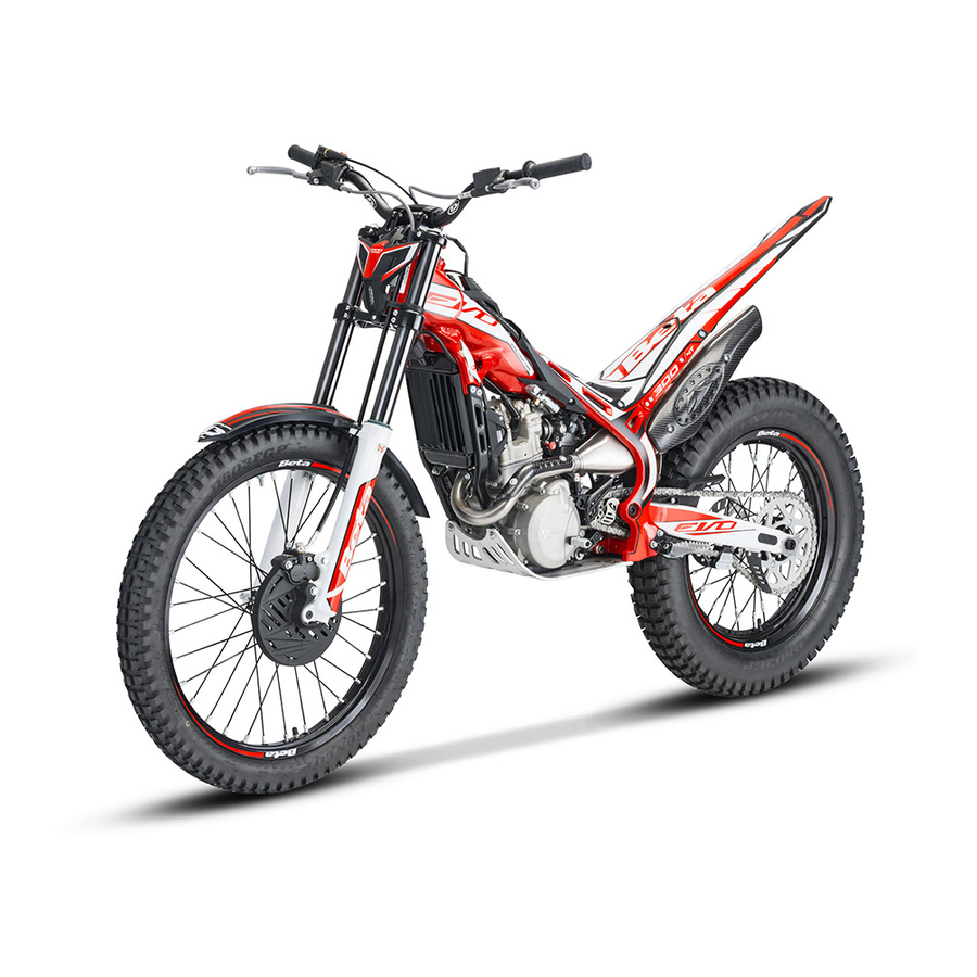
EVO 4T
Thanks for you preference, and have a good time! This hand-
book contains the information you need to properly operate and
maintain your motorcycle.
The data and specifi cations provided in this manual does not constitute an
engagement on the part of BETAMOTOR S.p.A. BETAMOTOR reserves the
right to make any changes and improvements to its models at any moment
and without notice.
GB
1
Advertisement
Chapters
Table of Contents
Troubleshooting

Subscribe to Our Youtube Channel
Related Manuals for Beta EVO 4T


Summary of Contents for Beta EVO 4T
- Page 1 EVO 4T Thanks for you preference, and have a good time! This hand- book contains the information you need to properly operate and maintain your motorcycle. The data and specifi cations provided in this manual does not constitute an engagement on the part of BETAMOTOR S.p.A. BETAMOTOR reserves the right to make any changes and improvements to its models at any moment and without notice.
- Page 2 • check that the plastics are properly fastened • engine bolts • shock absorber bolts/swingarm • wheel hubs/spokes • rear frame • pipe connections • tensioning the chain IMPORTANT For any servicing requirements, please get in contact with Beta- motor’s authorized service network.
-
Page 3: Table Of Contents
TABLE OF CONTENTS Operating instructions ................5 Ecologic guide ..................5 Riding safety ..................6 CHAPTER 1 GENERAL INFORMATION ..........7 Vehicle identifi cation data ............... 8 Familiarizing with the vehicle..............9 Specifi cations ..................10 Electrical system ................... 14 Recommended lubricants and liquids ............ - Page 4 Steering gear..................47 Oil fork ....................48 Tyres....................52 Chain ....................53 Headlight .................... 55 Rear tail light ..................56 Cleaning the vehicle ................57 Prolonged inactivity ................58 Scheduled maintenance vehicle ............59 CHAPTER 5 TROUBLESHOOTING ............ 61 Troubleshooting ................... 62...
-
Page 5: Operating Instructions
OPERATING INSTRUCTIONS • The vehicle must be accompanied by: number-plate, registration document, tax disc and insurance. • Do not carry animals, pets or loose objects that can stick out from the vehicle. • Riding without a crash helmet is forbidden. •... -
Page 6: Riding Safety
RIDING SAFETY • Observe the Highway Code. • Always put on and fasten a homologated helmet. • Always ride with the low beam on. • Always keep the crash helmet visor clean. • Avoid wearing garments with hanging ends. • Do not keep sharp or brittle objects in your pockets while riding. •... -
Page 7: Chapter 1 General Information
CHAPTER 1 GENERAL INFORMATION CONTENTS Vehicle identifi cation data ............... 8 Frame identifi cation ................8 Engine identifi cation ................8 Familiarizing with the vehicle..............9 Main parts ..................9 Specifi cations ..................10 Weight ................... 10 Vehicle dimensions ................10 Tyres .................... -
Page 8: Vehicle Identifi Cation Data
VEHICLE IDENTIFICATION DATA FRAME IDENTIFICATION Frame identifi cation data A are stamped on the right side of the steering head tube. ENGINE IDENTIFICATION Engine identifi cation data B are stamped in the area shown in the picture. In order to read it correctly, it is necessary to remove the silencer and disconnect the regulator connector. -
Page 9: Familiarizing With The Vehicle
FAMILIARIZING WITH THE VEHICLE 11 10 MAIN PARTS 1 Fuel tank 11 Engine 2 Tank cap 12 Front mudguard 3 Silencer 13 Rear mudguard 4 Rear shock absorber 14 Kick-start 5 Headlight 15 Gear lever 6 Rear light 16 Rear brake lever 7 Side stand 17 Front brake lever 8 Fork... -
Page 10: Specifi Cations
SPECIFICATIONS WEIGHT Dry weight ..................72 kg Front ..................36 kg Rear ................... 36 kg VEHICLE DIMENSIONS maximum length ................ 2005 mm maximum width ................850 mm wheelbase................1305 mm maximum height ............... 1115 mm ground clearance ................ 310 mm saddle height ................ -
Page 11: Front Suspension
FRONT SUSPENSION Version EVO 250 EVO 300 Wheel excursion [mm] Right fork leg Left fork leg Right fork leg Left fork leg K spring 7,65 7,65 [N/mm] Oil type Shell Tellus S2 V32 SAE 6,1 Oil level [mm] (edge rod with fork compressed) Register spring Full open... -
Page 12: Engine
ENGINE Version EVO 250 EVO 300 Type Single-cylinder, 4-stroke Single-cylinder, 4-stroke Bore x stroke 77 x 53,6 84 x 53,6 Displacement [cm 249,6 Pressure ratio 11,5:1 11,4:1 Fuel system carburetor carburetor CARBURETOR EVO 250 EVO 300 Version Homologated Competition* Homologated Competition* Carburetor type SE BSR33-79... -
Page 13: Gear Box
GEAR BOX Version EVO 250 EVO 300 Primary drive 18/63 18/63 Gear ratio 1st gear 13/36 13/36 Gear ratio 2nd gear 15/36 15/36 Gear ratio 3rd gear 16/30 16/30 Gear ratio 4th gear 24/27 24/27 Gear ratio 5th gear 28/21 28/21 Homologated Competition* Homologated Competition* Secondary drive... -
Page 14: Electrical System
ELECTRICAL SYSTEM ELECTRICAL DIAGRAM FOR HOMOLOGATED VERSION... -
Page 15: Legend Electrical Diagram For Homologated Version
LEGEND ELECTRICAL DIAGRAM FOR HOMOLOGATED VERSION R.H. front turn signal with bulb 12V - 10W Headlamp (double fi lament bulb) 12V-35/35W Position light with bulb 12V - 5W High beam indicator light with bulb 12V 1,2W Dashboard indicator light with bulb 12V 1,2W Turn signal indicator light with bulb 12V 1,2W L.H. -
Page 16: Electrical Diagram For Race Version
ELECTRICAL DIAGRAM FOR RACE VERSION... -
Page 17: Legend Electrical Diagram For Race Version
LEGEND ELECTRICAL DIAGRAM FOR RACE VERSION Headlamp with bulb 12V-20W Horn 12V Fuel cock Horn button Engine stop button Condenser 4700µF - 25V Light switch (black) Switch for change mapping (yellow) Tail light with bulb 12V - 3W 10) Generator 11) Pick-up 12) H.T. -
Page 18: Recommended Lubricants And Liquids
RECOMMENDED LUBRICANTS AND LIQUIDS For better operation and longer vehicle life, we advise you to use the products listed in the following chart: Engine Oil: 850cc Motul 7100 10w40 (For Competition use Motul 300V 10w40) Brake Fluid Motul RBF 600 Coolant/Antifreeze Motul Motocool Expert Fork Oil... -
Page 19: Chapter 2 Operation
CHAPTER 2 OPERATION CONTENTS Main parts ..................20 Fuel cock ..................20 Starter .................... 20 Hot start ..................20 Clutch lever ..................21 LH switch ..................21 RH switch ..................21 Front brake lever and gas control ............22 Gearchange lever................22 Brake pedal .................. -
Page 20: Main Parts
MAIN PARTS FUEL COCK Fuel valve has two positions: C : OFF Automatic. If the engine is shut off, the fuel supply is switched off and the fuel cannot fl ow from the tank to the carburetor. A: fuel supply always enabled. The fuel passes from the tank to the carburetor even with the engine off. -
Page 21: Clutch Lever
CLUTCH LEVER Clutch lever 1 is fi tted to the left-hand side of the handlebars. Screw A can be used to alter the home position of the lever (see Adjustments). LH SWITCH The off switch is positioned on the left-hand side of the handlebar and consists of the following: shutdowns engine: it is necessary to hold... -
Page 22: Front Brake Lever And Gas Control
FRONT BRAKE LEVER AND GAS CONTROL The front brake lever 1 and the gas throt- tle 2 are located on the right side of the handlebar. GEARCHANGE LEVER Gearchange lever is fi tted to the left side of the engine. The positions corresponding to the different gears are shown in the fi... - Page 23 SIDE STAND Press down side stand with the foot and lean the vehicle against it. Ensure that the ground is solid and the vehicle stands steadily. WARNING! The kickstand has an auto- matic closing device. When the vehicle weight on the kickstand is reduced, it closes automatically.
-
Page 24: Checks Before And After Use
CHECKS BEFORE AND AFTER USE For safe driving and long vehicle life you should: • Check all fl uid levels. • Check the correct operation of the brakes and brake pad wear (page 43). • Check pressure, general condition and thickness of tread (page 10). •... -
Page 25: Fuelling
FUELLING Use unleaded gasoline. Fuel tank capacity is shown on page To open the fuel tank’s cap, turn it anti- clockwise. To close the fuel tank’s cap, set it on the tank and crew it clockwise. -
Page 26: Startup
STARTUP Set the fuel tank tap to A (see page 20). - Check that the gears are in neutral (page 22). - Pull the clutch lever (page 21). KICKSTART (page 22): depress the kick-starter with a sharp move- ment of the foot. ATTENTION Once the pedal has been depressed, release it immediately. -
Page 27: Chapter 3 Adjustments
CHAPTER 3 ADJUSTMENTS CONTENTS Brakes ....................28 Front brake ..................28 Rear Brake..................28 Clutch ....................29 Adjustment of gas clearance ..............29 Accelerator ..................30 Adjusting the idle speed ..............30 Handlebar ..................30 Adjusting fork ..................30 Adjusting the rebound damper ............30 Adjusting the spring preload ............. -
Page 28: Brakes
BRAKES FRONT BRAKE The front brake is disk type with hydraulic control. The position of the lever is controlled through the use of register 1. Once the position of the lever has been changed, register 2 must be changed to restore the initial correct clearance. -
Page 29: Clutch
CLUTCH The position of the lever is controlled through the use of register 1. Once the position of the lever has been changed, register 2 must be changed to restore the initial correct clearance. The idle stroke of push rod must not be less than 0.9 mm 0,9 mm ATTENTION: reduced clearance leads to... -
Page 30: Accelerator
ACCELERATOR ADJUSTING THE IDLE SPEED In order to perform this operation correctly, we advise you to do it when the engine is hot, connecting an electric revolution counter to the spark plug wire. Then use a screwdriver on register screw A to calibrate the minimum with 1.100÷1.200 rpm. -
Page 31: Shock Absorber
ADJUSTING THE SPRING PRELOAD Spring preload is adjusted by means of screw 2. Turning clockwise will increase the preload, while rotating counter- clock- wise decreases the preload. For standard calibration, refer to page SHOCK ABSORBER ADJUSTING THE REBOUND DAMPER The hydraulic brake unit in extension deter- mines the behaviour in the extension phase of the shock absorber and can be adjusted using screw 1. -
Page 32: Suspension Adjustment According To The Motorcyclist's Weight
ADJUSTING THE SPRING PRELOAD To adjust the spring preload, use the pro- cedure described below. Loosen counter-ring 1, rotate ring 2 clock- wise to increase the spring preload (and consequently the shock absorber preload) or anticlockwise to decrease it. After obtaining the desired preload, turn counter-ring 1 until it stops against adjust- ing ring 2. -
Page 33: Chapter 4 Checks And Maintenance
CHAPTER 4 CHECKS AND MAINTENANCE CONTENTS Key to symbols..................34 Engine oil .................... 34 Check the level ................34 Replacement ................... 34 Coolant ....................36 Check the level ................36 Replacement ................... 37 Radiator grill ................... 38 Air fi lter ....................38 Removing and fi... -
Page 34: Key To Symbols
KEY TO SYMBOLS Tightening torque Threadlocker medium intensity ENGINE OIL CHECK THE LEVEL The engine oil level must be checked when the engine is warm. Let the engine run for a few minutes then turn it off. Keep the vehicle in vertical position relative to the ground. - Page 35 - Unscrew the plug 4 in the left-hand cas- ing and use pliers to extract the fi lter. Clean it carefully and blow it through with compressed air. Check for damage to the O-rings, and replace them if necessary. Refi t all the parts and tighten the plug to 15 Nm.
-
Page 36: Coolant
- Extract the paper fi lter using pliers. Check the condition of the O-ring too, and replace it if necessary. Change the fi lter and refi t the cover, tightening the three M6x20 bolts to 10 - Pour in the quantity of oil indicated on page 10. -
Page 37: Replacement
REPLACEMENT Position the vehicle on a fl at base and in a stable manner. Replacement of the coolant must take place when the engine is cold. 1) Unscrew cap 1. 2) Unscrew screw 2, collecting the liquid in a container. 10Nm 3) Drain the liquid. -
Page 38: Air Filter
RADIATOR GRILL Should the grill be obstructed proceed as follows: Remove the grill by pulling it towards the front of the vehicle. Shake and wash the grill. Reapply the grill pushing it towards the radiator. AIR FILTER Check after every ride. REMOVING AND FITTING AIR FILTER To access the fi... -
Page 39: Cleaning Air Fi Lter
CLEANING AIR FILTER - Thoroughly wash the fi lter with water and soap. - Dry the fi lter. - Wet the fi lter with specifi c oil and then remove the excess oil to prevent it from dripping. - If necessary also clean the interior of the fi... -
Page 40: Spark Plug
SPARK PLUG Keeping the spark plug in good condition will reduce fuel consumption and increase 0,5÷0,6 mm engine performance. To perform the check, simply slide off the electrical connection tube and unscrew the spark plug. Examine the distance between the electrodes with a feeler. This distance should be from 0.5÷0.6 mm. -
Page 41: Carburetor
CARBURETOR DRAINING THE CARBURETOR FLOAT CHAMBER If the carburetor tank needs to be emptied, proceed as described. Perform the opera- tion once the engine is cold. Turn the fuel cock to the “C” position (see page 20) Place tube 1 in a container to gather the fuel that fl... -
Page 42: Front Brake
FRONT BRAKE CHECK THE LEVEL OF THE FRONT BRAKE FLUID Check the level of the brake fl uid through sight A. The level of the fl uid should never fall below the mark in the sight. RESTORING THE LEVEL OF THE FRONT BRAKE FLUID To restore the level of the brake fl... -
Page 43: Bleeding The Front Brake
BLEEDING THE FRONT BRAKE To bleed air from the front brake circuit, proceed as follows: •Remove the rubber cap 1 from the valve •Open the sump cap. •Insert one end of a transparent tube into a container. •Pump with the brake lever 2/3 times and keep the lever pressed. -
Page 44: Rear Brake
REAR BRAKE CHECK THE LEVEL OF THE REAR BRAKE FLUID Check the level of the brake fl uid through sight A. The level of the fl uid should never fall below the mark in the sight. RESTORING THE LEVEL OF THE REAR BRAKE FLUID To restore the level of the brake fl... -
Page 45: Clutch Control
NOTE: During this procedure, continuously top up the brake pump thank to replace the oil that is out fl owing. •Remove the tube. •Replace the rubber cap. Close the oil reservoir cap. REAR BRAKE LINING CONTROL 2 mm In order to verify the wear condition of rear brake is enough to view the caliper from the back side, where is possible to glimpse the brake lining tails which will have to show... -
Page 46: Bleeding Clutch Control
If the level is lower than indicated proceed with refi lling. Use the liquid indicated on page 18 in the “Recommended lubricants and liquids” table. WARNING: The fl uid is extremely corrosive. Take care not to spill it on the paintwork. BLEEDING CLUTCH CONTROL •... -
Page 47: Steering Gear
STEERING GEAR CHECK OF STEERING GEAR Periodically check the play in the steering sleeve by moving the fork back and forth as shown in the fi gure. Whenever you feel play, adjust as described below: Loosen the screws 1. 10Nm Loosen the screw 2. -
Page 48: Oil Fork
OIL FORK The procedure for changing the oil in the forks is provided only for information. We recommend having the operation performed by a BETAMOTOR authorized workshop. REMOVING LEGS To replace, proceed as follows: Position the vehicle on the central bike stand. -
Page 49: Oil Replacement Left Leg
Empty the fork leg and the cartridge, drain- ing all the oil inside. Reassemble the cartridge on the fork leg tightening the fi xing screw, then refi ll oil in the cartridge. Pour in the quantity of liquid indicated on page 11. -
Page 50: Legs Assembly And Parts
LEGS ASSEMBLY AND PARTS Apply the legs to the vehicle and tighten the screws 1 to the torque indicated. ATTENTION: Tightening of the screws should be carried out by adjusting the torque wrench to to the stability torque with 10Nm repeated tightening until stability torque has been achieved. -
Page 51: Linkage Rear Suspension
NOTE: It is recommended not to wash with 10Nm water jets at high pressure in the zone of the linkage. Perform the check according to the times indicated in the table on page 59. To verify device, contact authorised Beta- motor customer service. -
Page 52: Tyres
TYRES Only fi t tyres approved by BETAMOTOR. Unsuitable tyres can adversely affect the road holding of the vehicle. • To protect your safety, immediately replace any damaged tyres. • Slick tyres adversely affect the road holding of the vehicle, especially on wet roads and in off-road riding. -
Page 53: Chain
CHAIN Checking the drive chain periodically to ensure longer chain life. Always keep it lubricated and clean of deposited dirt. Take special care in preventing the lubri- cant from coming into contact with the rear tyre or brake disc, otherwise the tyre grip and the action of the brake would be greatly reduced, making it very diffi... - Page 54 Rotate register 3 into the same position as register 2. Ensure the distance between chain and swingarm is that recommended. If the distance between chain and swingarm is not that recommended pro- ceed to readjustment. Tighten the pin to the torque indicated. 80Nm...
-
Page 55: Headlight
HEADLIGHT Keep the headlight glass clean at all times (page 57). REPLACING THE HEADLIGHT BULBS Dismantle the headlight mask removing the two retaining screws 1 indicated in the fi gure. Remove the screws 2 indicated in the fi gure. Take out the bulb assembly from the bulb holder. -
Page 56: Rear Tail Light
REAR TAIL LIGHT Keep the tail light glass clean at all times (see page 57). Remove the screws indicated in the fi gure. Remove the bulb holder from its place. Remove the bulb. To reassemble, proceed inversely as de- scribed above. -
Page 57: Cleaning The Vehicle
CLEANING THE VEHICLE WARNING: Do not clean your vehicle with a high-pressure device with a strong jet of water. Excessive pressure can reach electrical components, connectors, fl exible cables, bearings, etc and can damage or destroy them. WARNING: Wash motorbikes frequently that are used near the sea (salty air) and on roads subject to salt spreading in winter. -
Page 58: Prolonged Inactivity
PROLONGED INACTIVITY A few simple operations should be performed to keep the vehicle in good condition whenever it is to remain inactive for a long period (e.g. during the winter): • Thoroughly clean the vehicle. • Reduce the tyre pressures by approximately 30 percent, and if possible raise the tyres off the ground. -
Page 59: Scheduled Maintenance Vehicle
SCHEDULED MAINTENANCE VEHICLE Engine Spark plug Clutch Cylinder Piston sealing rings Piston Water pump shaft Oil seal water pump shaft Coolant Gear oil Oil net fi lters Paper fi lter Connecting rod Crankshaft bearings Gear Vehicle Rear shock absorber Linkage rear suspension Fork oil Steering bearings and steering clearance Wheel bearings... -
Page 61: Chapter 5 Troubleshooting
CHAPTER 5 TROUBLESHOOTING CONTENTS Troubleshooting ................... 62 Alphabetical index ................63... -
Page 62: Troubleshooting
TROUBLESHOOTING PROBLEM CAUSE REMEDY The engine turns over but Fuel cock in C position Turn the fuel cock in A position will not start Dirty carburettor jets Contact authorised BETAMOTOR customer service Spark plug dirty Clean or replace the spark plug Spark gap wrongly adjusted Restore the spark gap (page 40) - Page 63 ALPHABETICAL INDEX Accelerator ..................30 Adjusting fork ..................30 Adjustment of gas clearance ..............29 Air fi lter ....................38 Brakes ....................28 Breaking in..................24 Carburetor ..................41 Chain ....................53 Checks before and after use ..............24 Cleaning the vehicle ................57 Clutch ....................
- Page 64 Rear brake ..................44 Rear tail light ..................56 Recommended lubricants and liquids ............18 Riding safety ..................6 Scheduled maintenance vehicle ............59 Shock absorber..................31 Spark plug ..................40 Specifi cations ..................10 Startup ....................26 Steering gear..................47 Suspension adjustment according to the motorcyclist’s weight ....
Need help?
Do you have a question about the EVO 4T and is the answer not in the manual?
Questions and answers