Fujitsu PRIMERGY BX920 S3 Upgrade And Maintenance Manual
Server blade
Hide thumbs
Also See for PRIMERGY BX920 S3:
- Instruction manual (14 pages) ,
- Specifications (8 pages) ,
- Operating manual (66 pages)

Related Manuals for Fujitsu PRIMERGY BX920 S3


Summary of Contents for Fujitsu PRIMERGY BX920 S3
-
Page 1: Server Blade
Upgrade and Maintenance Manual - English PRIMERGY BX920 S3 Server Blade Upgrade and Maintenance Manual Edition February 2014... -
Page 2: Copyright And Trademarks
– The contents of this manual may be revised without prior notice. – Fujitsu assumes no liability for damages to third party copyrights or other rights arising from the use of any information in this manual. – No part of this manual may be reproduced in any form without the prior written permission of Fujitsu. - Page 3 The device has not been designed or manufactured for uses which demand an extremely high level of safety and carry a direct and serious risk of life or body if such safety cannot be assured. Upgrade and Maintenance Manual BX920 S3...
- Page 4 Please consult the sales staff of Fujitsu if intending to use this product for high safety use. Measures against momentary voltage drop This product may be affected by a momentary voltage drop in the power supply caused by lightning.
- Page 5 Only for the Japanese market: Although described in this manual, some sections do not apply to the Japanese market. These options and routines include: – CSS (Customer Self Service) Upgrade and Maintenance Manual BX920 S3...
- Page 6 Upgrade and Maintenance Manual BX920 S3...
-
Page 7: Table Of Contents
Opening the rack door ..... 54 4.2.1 Opening the rack door of a PRIMECENTER rack ..54 Upgrade and Maintenance Manual BX920 S3... - Page 8 Updating or recovering the iRMC ....80 5.2.2 Restoring BIOS settings ..... 82 Upgrade and Maintenance Manual BX920 S3...
- Page 9 Required tools ......108 6.3.2 Preliminary steps ......108 Upgrade and Maintenance Manual BX920 S3...
- Page 10 Concluding steps ..... . 141 SAS RAID HDD module ....143 Upgrade and Maintenance Manual BX920 S3...
- Page 11 ....167 8.1.1.4 Performance channel mode ....168 Upgrade and Maintenance Manual BX920 S3...
- Page 12 Removing a processor ..... 193 9.3.4 Concluding steps ......197 Upgrade and Maintenance Manual BX920 S3...
- Page 13 Concluding steps ..... . . 221 10.2.3 Replacing the UFM ..... . . 222 Upgrade and Maintenance Manual BX920 S3...
- Page 14 Concluding steps ......249 Server blade ......251 Upgrade and Maintenance Manual BX920 S3...
- Page 15 Indicators on the hot-plug HDD/SSD module ..265 12.4 Minimum startup configuration ....266 Upgrade and Maintenance Manual BX920 S3...
- Page 16 Contents Upgrade and Maintenance Manual BX920 S3...
-
Page 17: Version History
3.0 / May 2013 Chapter 5.1.4 and 5.2.3 changed 4.0 / August 2013 Mirror channel mode changed, chapter 11.1 corrections 5.0 / November 2013 Cross-references corrected in chapter 5 6.0 / February 2014 Chapter 5.2.15 Upgrade and Maintenance Manual BX920 S3... - Page 18 Upgrade and Maintenance Manual BX920 S3...
-
Page 19: Introduction
"Documents you need at hand" on page CAUTION! The document at hand comprises procedures of a wide range of complexity. Check the profile of qualification for technicians before assigning tasks. Before you start, carefully read "Classification of procedures" on page Upgrade and Maintenance Manual BX920 S3... -
Page 20: Where To Find Which Information
For information on documents you need to have with you when leaving for maintaining a server see "Documents you need at hand" on page All documentation on PRIMERGY hardware and ServerView software is available online from the Fujitsu manuals server at: – http://manuals.ts.fujitsu.com (global market) –... -
Page 21: Notational Conventions
"Classification of procedures" on page 25 indicates the average task duration, see "Average task duration" on page 28 Upgrade and Maintenance Manual BX920 S3... - Page 22 Introduction Upgrade and Maintenance Manual BX920 S3...
-
Page 23: Before You Start
"Tools you need at hand" on page Installing optional components The "PRIMERGY BX920 S3 Server Blade Operating manual" gives an introduction to server features and provides an overview of available hardware options. Use the Fujitsu ServerView Suite management software to prepare hardware expansions. - Page 24 Before you start Please contact your local Fujitsu customer service partner for details on how to order expansion kits or spare parts. Use the Fujitsu Illustrated Spares Catalog to identify the required spare part and obtain technical data and order information.
-
Page 25: Classification Of Procedures
At the beginning of each procedure, the involved unit type is indicated by one of the symbols introduced in this section. Please ask your local Fujitsu service center for more detailed information. 2.1.1 Customer Replaceable Units (CRU) -
Page 26: Upgrade And Repair Units (Uru)
Components that are handled as Upgrade Units – Processors (upgrade kits) – Mezzanine cards – SAS RAID HDD module – Flash Backup Unit (FBU) – Memory modules Components that are handled solely as Repair Units – CMOS battery Upgrade and Maintenance Manual BX920 S3... -
Page 27: Field Replaceable Units (Fru)
Maintenance procedures involving Field Replaceable Units must be performed exclusively by Fujitsu service personnel or technicians trained by Fujitsu. Please note that unauthorized interference with the system will void the warranty and exempt the manufacturer from all liability. Components that are handled as Field Replaceable Units –... -
Page 28: Average Task Duration
Reassembling the server blade, installing unit installation the server blade in the system unit Booting time depends on hardware and Starting up software configuration and may vary significantly. Table 1: Calculation of the average task duration Upgrade and Maintenance Manual BX920 S3... -
Page 29: Tools You Need At Hand
Table 2: List of required tools and used screws Documents you need at hand Maintenance procedures may include references to additional documentation. When preparing the maintenance task, ensure that all required manuals are available according to the overview below. Upgrade and Maintenance Manual BX920 S3... - Page 30 – Unless stated otherwise, all manuals are available online at http://manuals.ts.fujitsu.com under Industry standard servers or from the ServerView Suite DVD 2 supplied with your PRIMERGY server. For the Japanese market please use the following address: http://jp.fujitsu.com/platform/server/primergy/manual/ Upgrade and Maintenance Manual BX920 S3...
- Page 31 ServerView Suite DVD 2, online, or as a " 安全上のご注意 " for the printed copy Japanese market "PRIMERGY BX920 S3 Server available from the ServerView Suite DVD 2 Blade" Operating Manual or online "D3142 BIOS Setup Utility for Information on configurable BIOS options PRIMERGY BX920 S3"...
- Page 32 Additional documentation http://manuals.ts.fujitsu.com under Industry standard servers - Expansion Cards - Storage Adapters – Rack documentation – Operating system documentation, online help Third party documentation – Peripherals documentation Table 3: Documentation you need at hand Upgrade and Maintenance Manual BX920 S3...
-
Page 33: Important Information
Failure to do so can cause electric shock or damage. Before starting up During installation and before operating the device, observe the instructions ● on environmental conditions for your device. Upgrade and Maintenance Manual BX920 S3... - Page 34 Otherwise you run the risk of losing data if, for example, the server is still running but a peripheral device (e.g. memory subsystem) fails during a power outage. Data cables must be adequately shielded. ● Upgrade and Maintenance Manual BX920 S3...
- Page 35 Before installing/removing internal options to/from the server, turn off the ● server, all peripheral devices, and any other connected devices. Also unplug all power cords from the outlet. Failure to do so can cause electric shock. Upgrade and Maintenance Manual BX920 S3...
- Page 36 All batteries containing pollutants are marked with a symbol (a crossed-out ● garbage can). In addition, the marking is provided with the chemical symbol of the heavy metal decisive for the classification as a pollutant: Cd Cadmium Hg Mercury Pb Lead Upgrade and Maintenance Manual BX920 S3...
- Page 37 Keep the optical disk tray closed to prevent foreign matter, such as dust, from entering the optical disk drive. Hold CDs/DVDs/BDs by their edges to avoid contact with the disk ● surface. Upgrade and Maintenance Manual BX920 S3...
- Page 38 The optical disk drive contains a light-emitting diode (LED), which under certain circumstances produces a laser beam stronger than laser class 1. Looking directly at this beam is dangerous. Never remove parts of the optical disk drive casing! Upgrade and Maintenance Manual BX920 S3...
- Page 39 Place all the components on a pad which is free of electrostatic charge. ● For a detailed description of how to handle ESD components, see the relevant European or international standards (EN 61340-5-1, ANSI/ESD S20.20). Upgrade and Maintenance Manual BX920 S3...
-
Page 40: Ce Conformity
A connector. CE conformity The system complies with the requirements of the EC directives 2004/108/EC regarding "Electromagnetic Compatibility" and 2006/95/EC "Low Voltage Directive". This is indicated by the CE marking (CE = Communauté Européenne). Upgrade and Maintenance Manual BX920 S3... -
Page 41: Fcc Class A Compliance Statement
Consult the dealer or an experienced radio/TV technician for help. ● Fujitsu is not responsible for any radio or television interference caused by unauthorized modifications of this equipment or the substitution or attachment of connecting cables and equipment other than those specified by Fujitsu. The correction of interferences caused by such unauthorized modification, substitution or attachment will be the responsibility of the user. -
Page 42: Environmental Protection
Important information Environmental protection Environmentally-friendly product design and development This product has been designed in accordance with the Fujitsu standard for "environmentally friendly product design and development". This means that key factors such as durability, selection and labeling of materials, emissions, packaging, ease of dismantling and recycling have been taken into account. - Page 43 Details regarding the return and recycling of devices and consumables within Europe can also be found in the "Returning used devices" manual, via your local Fujitsu branch or from our recycling center in Paderborn: Fujitsu Technology Solutions Recycling Center D-33106 Paderborn Tel.
- Page 44 Important information Upgrade and Maintenance Manual BX920 S3...
-
Page 45: Basic Hardware Procedures
The "PRIMERGY BX920 S3 Server Blade Operating Manual" gives an introduction to server blade features and provides an overview of available hardware options. Use the Fujitsu ServerView Suite management software to plan the upgrade or replacement of hardware components. ServerView Suite documentation is available online at http://manuals.ts.fujitsu.com... - Page 46 Systems ServerView Management Blade S1 User Interface Description". Ê Open the Management Agent – Management Agent Information menu to view the Management Agent Administrative URL. Ê Login to the management blade web interface as described above. Upgrade and Maintenance Manual BX920 S3...
-
Page 47: Locating The Defective Server Blade
Ê Remember to switch off the ID indicator after the maintenance task has been concluded successfully. 4.1.3 Determining the error class The Local Service Concept (LSC) allows you to identify defective server blade components. Failure events are assigned to one of two error classes: Upgrade and Maintenance Manual BX920 S3... - Page 48 Global Error and CSS LEDs indicate, if the defective component is a customer replaceable unit or if maintenance personnel needs to be dispatched to replace the part. The indicators also light up in standby mode and after a server blade restart due to a power failure. Upgrade and Maintenance Manual BX920 S3...
-
Page 49: Global Error Indicator
Check the System Event Log (SEL) as described in section "Viewing the SEL" on page – Software / agent related errors: Check the ServerView System Monitor, available on Windows or Linux based server blades with ServerView agents installed. Upgrade and Maintenance Manual BX920 S3... -
Page 50: Customer Self Service (Css) Indicator
For further information, please refer to the "ServerView System Monitor" user guide, available online at http://manuals.ts.fujitsu.com (for the Japanese market: http://jp.fujitsu.com/platform/server/primergy/manual/) or from the ServerView Suite DVD 2 supplied with your PRIMERGY server blade. 4.1.3.2 Customer Self Service (CSS) indicator Figure 5: CSS error indicator in front panel Ê... -
Page 51: Locating The Defective Component
Figure 6: Onboard indicators and Indicate CSS button No. Description Indicate CSS button Using the Indicate CSS button Ê Shut down the server blade as described in section "Shutting down the server blade" on page Upgrade and Maintenance Manual BX920 S3... -
Page 52: Component Leds
Fabric 1 link established System is ok yellow CSS error detected flashing yellow on Prefailure event detected No critical event orange Error detected (requires service intervention) Global Error flashing Prefailure event detected (requires service orange on intervention) Upgrade and Maintenance Manual BX920 S3... - Page 53 (see section "Determining the error class" on page 47). If the system has been powered off to replace a non hot-plug unit, a system of PRIMERGY diagnostics indicators guides you to the faulty component. Upgrade and Maintenance Manual BX920 S3...
-
Page 54: Opening The Rack Door
Ê Pull the green marked grip to open the door. For further information, refer to the "PRIMECENTER M1 Rack" user guide available online at http://manuals.ts.fujitsu.com or from the ServerView Suite DVD 2 supplied with your PRIMERGY server. Upgrade and Maintenance Manual BX920 S3... -
Page 55: Shutting Down The Server Blade
On / Off button will perform a graceful shutdown. Ê Switch on the ID indicator on the front panel of the server blade as described in section "Locating the defective server blade" on page Upgrade and Maintenance Manual BX920 S3... -
Page 56: Removing A Server Blade
Ê If applicable, open the rack door as described in section "Opening the rack door" on page Ê Shut down and power off the server blade as described in section "Shutting down the server blade" on page Upgrade and Maintenance Manual BX920 S3... -
Page 57: Removing The Server Blade From The System Unit
Ê Push the release lever (1) up slightly to unlock the ejection lever (2). Ê Swivel the ejection lever down until it is horizontal. Ê Pull the server blade out of the system unit. Upgrade and Maintenance Manual BX920 S3... -
Page 58: Opening The Server Blade
Figure 9: Removing the cover Ê Push the locking lever in the direction of the arrow (1). Slide the housing cover backwards as far as possible (2). Ê Ê Take off the housing cover. Upgrade and Maintenance Manual BX920 S3... -
Page 59: Closing The Server Blade
In order to comply with applicable EMC regulations (regulations on ● electromagnetic compatibility) and satisfy cooling requirements, the PRIMERGY BX920 S3 server blade must not run while the cover is removed. For further safety information, please refer to chapter "Important ●... -
Page 60: Installing The Server Blade In The System Unit
You will find more detailed information on this in the operating manual for the system unit. Installing the Server Blade CAUTION! Follow the safety instructions and information in section "Modules with Electrostatic-Sensitive Devices" on page Upgrade and Maintenance Manual BX920 S3... - Page 61 Basic hardware procedures Figure 11: Installing the Server Blade Ê Open the release lever. Ê Push the server blade as far as possible into the slot. Upgrade and Maintenance Manual BX920 S3...
- Page 62 It is not a breakdown though the power supply of the server blade intermittently repeats turning on/cutting when "Automatic inventory collection (Automatic Inventory Retrieval)" of the management braid is set to "Automatic" (default value) after the installation of the server blade. Upgrade and Maintenance Manual BX920 S3...
-
Page 63: Switching On The Server Blade
● In order to comply with applicable EMC regulations (regulations on electromagnetic compatibility) and satisfy cooling requirements, the PRIMERGY BX920 S3 server blade must not run while the cover is removed. Follow the safety instructions in chapter "Important information" on ●... -
Page 64: Concluding Software Tasks
"Updating the NIC configuration file in a Linux environment" on page 94 – "Enabling BitLocker functionality" on page 96 – "Performing a RAID array rebuild" on page 97 – "Looking up changed MAC / WWN addresses" on page 97 Upgrade and Maintenance Manual BX920 S3... -
Page 65: Closing The Rack Door
Ê Insert and turn the key counter-clockwise as far as it will go. For further information, refer to the "PRIMECENTER M1 Rack" user guide available online at http://manuals.ts.fujitsu.com or from the ServerView Suite DVD 2 supplied with your PRIMERGY server. Upgrade and Maintenance Manual BX920 S3... - Page 66 Basic hardware procedures Upgrade and Maintenance Manual BX920 S3...
-
Page 67: Basic Software Procedures
5.1.2.1 Checking the server blade status via management blade web interface To check the server blade status proceed as follows. Ê Enter the management blade web interface. Ê Open the Components – System menu. Upgrade and Maintenance Manual BX920 S3... -
Page 68: Checking The Server Blade Status Via Irmc
The iRMC web interface opens, where you can administer the server blade remotely. For further information refer to the "Integrated Remote Management Controller" user guides available online at http://manuals.ts.fujitsu.com or from the ServerView Suite DVD 2 supplied with your PRIMERGY server. Upgrade and Maintenance Manual BX920 S3... -
Page 69: Saving Bios Settings
Saving BIOS settings The description for saving the BIOS settings can be found in chapter „Save & Exit menu“ in the "D3142 BIOS Setup Utility for PRIMERGY BX920 S3" reference manual. For the Japanese market, follow the instructions provided separately. -
Page 70: Disabling Bitlocker Functionality
BitLocker setup wizard available either from the Control Panel or Windows Explorer: Ê Open BitLocker Drive Encryption by clicking the Start button, clicking Control Panel, clicking Security, and then clicking Bitlocker Drive Encryption. Upgrade and Maintenance Manual BX920 S3... -
Page 71: Disabling Boot Watchdog Functionality
BitLocker setup wizard, modify the BitLocker Group Policy settings. For further information on how to disable BitLocker drive encryption, please refer to the Microsoft Knowledge Base. Fujitsu service partners will find additional information (also available in Japanese) on the Fujitsu Extranet web pages. 5.1.7... - Page 72 Ê Save your changes and exit the BIOS. For detailed information on how to access the BIOS and modify settings, refer to the "D3142 BIOS Setup Utility for PRIMERGY BX920 S3" reference manual. Configuring boot watchdog settings using the management blade web interface Ê...
-
Page 73: Verifying And Configuring The Backup Software Solution
Procedures may differ depending on the backup software. For details, refer to the dedicated documentation provided separately. Further information on suitable backup software solutions and related documentation is available to Fujitsu service partners from the Fujitsu Extranet pages. Upgrade and Maintenance Manual... -
Page 74: Note On Server Maintenance In A Multipath I/O Environment
Continue as follows: Ê If performing an offline driver update, first of all prepare the ServerView Update DVD: Ê Download the latest ServerView Update DVD image from the Fujitsu FTP server at ftp://ftp.ts.fujitsu.com/images/serverview. Ê Burn the image to a DVD. - Page 75 FC/iSCSI connections on the system. Ask the system administrator to enable the FC/iSCSI connections to the server blade via FC/LAN connection blade command. Ê If necessary, perform this procedure for all remaining servers within the Multipath environment. Upgrade and Maintenance Manual BX920 S3...
-
Page 76: Switching On The Id Indicator
Ê Press the Locate button in the server blade status frame to switch on the ID indicator. Using ServerView Operations Manager Ê In ServerView Operations Manager Single System View and press the Locate button in the title bar to switch on the ID indicator. Upgrade and Maintenance Manual BX920 S3... -
Page 77: Completing The Maintenance Task
(EMEA market) http://jp.fujitsu.com/platform/server/primergy/downloads/ (Japanese market) Fujitsu does not assume responsibility for any damage done to the server or for the loss of any data resulting from BIOS updates. 5.2.1.1 Updating or recovering the system board BIOS TFTP update procedure Ê... - Page 78 Do not interrupt the BIOS recovery process after it has started. If the process is interrupted, the BIOS may be permanently corrupted. Ê Switch off the server blade as described in section "Shutting down the server blade" on page Ê Remove the Y cable. Upgrade and Maintenance Manual BX920 S3...
- Page 79 Ê Switch off the server blade as described in section "Shutting down the server blade" on page Ê Remove the Y-cable. Ê Remove the server blade from the system unit as described in section "Removing a server blade" on page Upgrade and Maintenance Manual BX920 S3...
-
Page 80: Updating Or Recovering The Irmc
The Update Progress History box provides information on the update progress. CAUTION! Do not interrupt the iRMC upgrade process after it has started. If the process is interrupted, the iRMC may be permanently corrupted. Upgrade and Maintenance Manual BX920 S3... - Page 81 Ê Remove the Y-cable. Ê Switch on the server blade as described in section "Switching on the server blade" on page Ê You can now put the server blade back into operation. Upgrade and Maintenance Manual BX920 S3...
-
Page 82: Restoring Bios Settings
5.2.2 Restoring BIOS settings The description for restoring the BIOS settings can be found in chapter „Flash BIOS Update“ in the "D3142 BIOS Setup Utility for PRIMERGY BX920 S3" reference manual. For the Japanese market, follow the instructions provided separately. - Page 83 Ê Open the iRMC S3 - Save Configuration. Ê Select the backup file stored in the file system of FST in section "Import iRMC S3 Firmware settings in ServerView® WinSCU XML format from file". Ê Click the Apply button. Upgrade and Maintenance Manual BX920 S3...
-
Page 84: Updating Mezzanine Card Firmware
"Local System Update for PRIMERGY Servers" user guide Using the flash tool The latest firmware files are available as ASPs (Autonomous Support Packages) for Windows or as DOS tools from the Fujitsu support web pages at http://ts.fujitsu.com/support/. Ê Select Drivers & Downloads. -
Page 85: Enabling Option Rom Scan
When iSCSI is used via an onboard CNA, from the Advanced menu select Onboard Devices Configuration - Onboard CNA OpROM. Ê Identify the desired mezzanine card slot and set its Launch Slot # OpROM setting to Enabled. Ê Save your changes and exit the BIOS. Upgrade and Maintenance Manual BX920 S3... -
Page 86: Verifying And Configuring The Backup Software Solution
For detailed information on how to access the BIOS and modify settings, refer to the "D3142 BIOS Setup Utility for PRIMERGY BX920 S3" reference manual. Ê From the Advanced menu select Option ROM Configuration. When iSCSI is used via an Onboard CNA, From the Advanced menu select Onboard Devices Configuration - Onboard CNA OpROM. -
Page 87: Resetting The Boot Retry Counter
Procedures may differ depending on the backup software. For details, refer to the dedicated documentation provided separately. Further information on suitable backup software solutions and related documentation is available to Fujitsu service partners from the Fujitsu Extranet pages. Re-enabling backup drives... -
Page 88: Resetting The Boot Retry Counter
Ê Open the Components – System – Server Blades – Server Blade-x menu for the desired server blade. Ê Select the Configuration tab and scroll to the ASR box. Ê Under Retry Counter 0-max. specify the maximum number of boot attempts (0 to 7). Upgrade and Maintenance Manual BX920 S3... -
Page 89: Enabling Boot Watchdog Functionality
Ê Save your changes and exit the BIOS. For detailed information on how to access the BIOS and modify settings, refer to the "D3142 BIOS Setup Utility for PRIMERGY BX920 S3" reference manual. Configuring boot watchdog settings using the management blade web interface Ê... -
Page 90: Enabling Replaced Components In The System Bios
Ê Reset replaced components to Enable. Ê Save your changes and exit the BIOS. For detailed information on how to access the BIOS and modify settings, refer to the "D3142 BIOS Setup Utility for PRIMERGY BX920 S3" reference manual. 5.2.10 Verifying the memory mode If a memory module fails, the server blade will reboot and the defective module will be disabled. -
Page 91: Verifying The System Time Settings
Ê Save your changes (if applicable) and exit the BIOS. For detailed information on how to access the BIOS and modify settings, refer to the "D3142 BIOS Setup Utility for PRIMERGY BX920 S3" reference manual. 5.2.11 Verifying the system time settings This task only applies to Linux environments. -
Page 92: Viewing And Clearing The System Event Log (Sel)
Ê Save your changes and exit the BIOS. For detailed information on how to access the BIOS and modify settings, refer to the "D3142 BIOS Setup Utility for PRIMERGY BX920 S3" reference manual. 5.2.12 Viewing and clearing the System Event Log (SEL) 5.2.12.1 Viewing the SEL... -
Page 93: Saving The Sel
This option is only available, if a USB memory stick is connected to the managment blade. Ê Click the Start button to save all available management blade and server blade event logs as text file to the selected medium. Upgrade and Maintenance Manual BX920 S3... -
Page 94: Clearing The Sel
Linux OS, the MAC address will change but not automatically be updated in the definition file. In order to prevent communication problems, it is necessary to update the changed MAC address stored in the related ifcfg-eth<x> definition file. Upgrade and Maintenance Manual BX920 S3... - Page 95 If the system board or network controller offers multiple LAN ports, it is necessary to update the remaining ifcfg-eth<x> definition files accordingly. Ê Update the NIC configuration file to reflect the new card sequence and MAC address. Upgrade and Maintenance Manual BX920 S3...
-
Page 96: Enabling Bitlocker Functionality
Ê Follow the instructions in the BitLocker Setup wizard. For further information on how to enable BitLocker drive encryption, please refer to the Microsoft Knowledge Base. Fujitsu service partners will find additional information (also available in Japanese) on the Fujitsu Extranet web pages. Upgrade and Maintenance Manual... -
Page 97: Performing A Raid Array Rebuild
5.2.16.1 Looking up MAC addresses Ê Open a virtual console for your server blade as described in section "Launching a video redirection to a server blade" on page Ê Switch on or restart your server blade. Upgrade and Maintenance Manual BX920 S3... -
Page 98: Looking Up Wwn Addresses
Ê Under Emulex Adapters in the System you will find all available Emulex adapters and their WWN addresses. Ê Note down the new 16-digit WWN address. Ê Press [Esc] to exit the Emulex BIOS utility. Ê Inform the customer about the changed WWN address. Upgrade and Maintenance Manual BX920 S3... -
Page 99: Using The Chassis Id Prom Tool
After replacing the server blade, system information has to be entered using the ChassisId_Prom Tool. The tool and further instructions are available to maintenance personnel from the Fujitsu Technology Solutions Extranet: http://partners.ts.fujitsu.com/com/service/intelservers/tools For the Japanese market, follow the instructions provided separately. -
Page 100: After Replacing The Server Blade
ID indicator. Using ServerView Operations Manager Ê In ServerView Operations Manager Single System View and press the Locate button in the title bar to switch off the ID indicator. Upgrade and Maintenance Manual BX920 S3... -
Page 101: Hard Disk Drives / Solid State Drives
Be careful not to hit the hard disk drive or bring it into contact with ● metallic objects. Handle the device on a shock and vibration free surface. ● Upgrade and Maintenance Manual BX920 S3... -
Page 102: Basic Information
Basic information The hard disk drives or solid state drives which can be ordered for the PRIMERGY BX920 S3 are supplied already mounted in an installation frame so that defective drives can be replaced and new drives can be added during operation. -
Page 103: General Equipping Rules
– Solid state drives (SSDs) are always equipped before installing hard disk drives. – If only one HDD/SSD module is installed, the HDD/SSD module will be installed in position 0. Free bays must be equipped with a dummy module. Upgrade and Maintenance Manual BX920 S3... -
Page 104: Installing A 2.5-Inch Hdd/Ssd Module
"Onboard Controller SAS Upgrade (ROM1 SCU key)" on page 239. 6.2.3 Removing the 2.5-inch dummy module Dummy modules protect free bays against environmental impact. Remove the dummy module before installing an additional HDD/SSD module. Upgrade and Maintenance Manual BX920 S3... - Page 105 HDD/SSD module and do not install a new one in its place, put the dummy module back in its place for cooling, to comply with EMC regulations (regulations regarding electromagnetic compatibility), and for protection against fire. Ensure that the dummy module engages correctly in the bay. Upgrade and Maintenance Manual BX920 S3...
-
Page 106: Installing The 2.5-Inch Hdd/Ssd Module
1. Press the two green tabs of the locking lever together (1). 2. Push the handle of the HDD/SSD module fully in the direction of the arrow (2). The HDD/SSD module is now unlocked. Upgrade and Maintenance Manual BX920 S3... - Page 107 Ê Carefully push the HDD/SSD module into the empty bay until it stops. Figure 19: Installing the 2.5-inch HDD/SSD module Ê Push the handle completely in the direction of the arrow until the locking mechanism engages. Upgrade and Maintenance Manual BX920 S3...
-
Page 108: Concluding Steps
Ensure that the HDD/SSD module to be removed is not combined into a RAID array. If the drive is part of a RAID array, you first need to delete the array using ServerView RAID Manager. Upgrade and Maintenance Manual BX920 S3... -
Page 109: Removing The 2.5-Inch Hdd/Ssd Module
Ê Wait for at least 30 seconds. This period is necessary for the RAID controller to recognize that an HDD/SSD module has been removed and for the hard disk drive to come to a stop. Upgrade and Maintenance Manual BX920 S3... -
Page 110: Installing The 2.5-Inch Dummy Module
Figure 21: Installing the 2.5-inch dummy module Ê Push the dummy module into the empty bay until it engages. 6.3.5 Concluding steps Perform the following procedures: "Closing the rack door" on page 65 Ê Upgrade and Maintenance Manual BX920 S3... -
Page 111: Replacing A 2.5-Inch Hdd/Ssd Module
Ê Set the drive to "Offline" via the software (RAID controller configuration software), before removing an HDD/SSD module that is not defective. 6.4.1 Required tools Preliminary and concluding steps: tool-less ● Main steps: tool-less ● Upgrade and Maintenance Manual BX920 S3... -
Page 112: Preliminary Steps
Concluding steps Perform the following procedures: "Closing the rack door" on page 65 Ê Ê If applicable, please observe the notes on RAID rebuild in section "Performing a RAID array rebuild" on page 97 Upgrade and Maintenance Manual BX920 S3... -
Page 113: Replacing Hdd/Ssd Backplanes
Ê Open the server blade as described in section "Opening the server blade" on page Ê Remove the HDD/SSD module from the relevant bay as described in section "Removing the 2.5-inch HDD/SSD module" on page 109. Upgrade and Maintenance Manual BX920 S3... -
Page 114: Removing The Hdd/Ssd Backplane
Hard disk drives / solid state drives 6.5.3 Removing the HDD/SSD backplane Figure 22: Removing the HDD/SSD backplane Ê Lift the HDD/SSD backplane up and remove it from the fixing brackets (1). Upgrade and Maintenance Manual BX920 S3... -
Page 115: Installing The Hdd/Ssd Backplane
Both backplane variants have the same form factor, so note the labeling (see ovals). Figure 24: Installing the HDD/SSD backplane Ê Lift the HDD/SSD backplane over the fixing brackets (1). Ê Press the HDD/SSD backplane into the slot (see arrows). Upgrade and Maintenance Manual BX920 S3... -
Page 116: Concluding Steps
Ê If applicable, close the rack door as described in section "Closing the rack door" on page Ê If BitLocker functionality is used and has been disabled before starting the maintenance task, re-enable BitLocker as described in section "Enabling BitLocker functionality" on page Upgrade and Maintenance Manual BX920 S3... -
Page 117: Expansion Cards And Backup Units
If devices are installed or disassembled using methods other than ● those outlined in this chapter, the warranty will be invalidated. For further information, please refer to chapter "Important ● information" on page Upgrade and Maintenance Manual BX920 S3... -
Page 118: Mezzanine Cards
Mezzanine cards 7.1.1 Basic information One or two mezzanine cards can be installed in a BX920 S3 server blade. Additional Fibre Channel, SAS, Ethernet and/or Infiniband I/O channels can be set up using these cards. All mezzanine cards have the same form factor. - Page 119 Figure 26: Carrier for mezzanine cards with two "x8" riser cards Figure 27: Carrier for mezzanine cards with one "x8" and one "x16" (2) riser card Note the numbering of the mezzanine card slots. Upgrade and Maintenance Manual BX920 S3...
-
Page 120: Installing Riser Cards
Expansion cards and backup units 7.1.1.1 Installing riser cards Figure 28: Installing the riser card x8 Ê Connect the riser card to the carrier. Make sure that the green clips click into place. Upgrade and Maintenance Manual BX920 S3... - Page 121 Expansion cards and backup units Figure 29: Installing the riser card x16 Ê Connect the riser card to the carrier. Make sure that the green clips click into place. Upgrade and Maintenance Manual BX920 S3...
-
Page 122: Removing Riser Cards
Expansion cards and backup units 7.1.1.2 Removing riser cards Figure 30: Removing the riser card x8 Ê Remove the riser card from the holder at the slot of mezzanine card 2. Upgrade and Maintenance Manual BX920 S3... - Page 123 Expansion cards and backup units Figure 31: Removing the riser card x16 Ê Remove the riser card from the holder. Upgrade and Maintenance Manual BX920 S3...
-
Page 124: Population Rules For Mezzanine Cards
Population rules for mezzanine cards in the BX900 S1/S2 system unit Fabric 1 Fabric 2 Fabric 3 Fabric 4 Figure 33: Connection blade slots The table below shows the connections of the connection blade slots to the slots of the mezzanine cards. Upgrade and Maintenance Manual BX920 S3... - Page 125 If a 10 Gb Ethernet mezzanine card or a 10Gb CNA mezzanine card is ● installed in slot 1 of a server blade, at least one 10 Gb Ethernet connection blade must be installed in fabric 2 of the system unit. Upgrade and Maintenance Manual BX920 S3...
- Page 126 3. You can install combinations of FC, Ethernet, Infiniband and SAS ● mezzanine cards in a server blade. In this case, the mezzanine card slots may be equipped as follows: Upgrade and Maintenance Manual BX920 S3...
- Page 127 "SAS RAID HDD module" on page 143. For the latest information on supported expansion cards, refer to your server’s hardware configurator available online at the following address: for the EMEA market: http://ts.fujitsu.com/products/standard_servers/tower/primergy_bx920s3.html for the Japanese market: http://jp.fujitsu.com/platform/server/primergy/system/ Upgrade and Maintenance Manual BX920 S3...
- Page 128 If a 10 Gb Ethernet mezzanine card or a 10Gb CNA mezzanine card is ● installed in slot 1 of a server blade, at least one 10 Gb Ethernet connection blade must be installed in CB slot 2 of the system unit. Upgrade and Maintenance Manual BX920 S3...
- Page 129 You can install a combination of FC, Ethernet and Infiniband mezzanine ● cards in a server blade. In this case, the Ethernet mezzanine card should be installed in slot 1 and the FC or Infiniband mezzanine card in slot 2 of the server blade. Upgrade and Maintenance Manual BX920 S3...
-
Page 130: Installing Mezzanine Cards
"Opening the server blade" on page Ê When installing a SAS Expander mezzanine card make sure, that an SAS RAID HDD module is installed as described in section "Installing the SAS RAID HDD module" on page 144. Upgrade and Maintenance Manual BX920 S3... -
Page 131: Installing A Mezzanine Card
The following section illustrates how to install a mezzanine card in slot 2. Removing the mezzanine cards carrier Figure 35: Removing the mezzanine cards carrier Ê Remove the mezzanine cards carrier from the server blade housing by lifting it up, keeping it as horizontal as possible. Upgrade and Maintenance Manual BX920 S3... - Page 132 Ê Place the mezzanine card on the two guide pins (1) at the slot of mezzanine card 2 and press the mezzanine card down so that it clicks into place between the two clips (2). Upgrade and Maintenance Manual BX920 S3...
- Page 133 Ê Connect the riser card to the mezzanine card. Make sure that the green clips click into place. Mezzanine card 1 is fastened to the carrier with the component side facing downward. Mezzanine card 1 is otherwise installed in the same way as mezzanine card 2. Upgrade and Maintenance Manual BX920 S3...
- Page 134 Ê Install the carrier with the mezzanine cards in the server blade housing. As you do this, the riser cards are inserted in the corresponding system board slots. Make sure that the coding on the carrier matches that on the server blade housing. Upgrade and Maintenance Manual BX920 S3...
-
Page 135: Concluding Steps
Ê If BitLocker functionality is used and has been disabled before starting the maintenance task, re-enable BitLocker as described in section "Enabling BitLocker functionality" on page Ê If applicable, restore LAN teaming configurations as described in section "Configuring LAN teaming" on page Upgrade and Maintenance Manual BX920 S3... -
Page 136: Removing Mezzanine Cards
Ê Remove the server blade from the system unit as described in section "Removing the server blade from the system unit" on page Ê Open the server blade as described in section "Opening the server blade" on page Upgrade and Maintenance Manual BX920 S3... -
Page 137: Removing A Mezzanine Card
Ê Remove the carrier from the server blade housing by lifting it up, keeping it as horizontal as possible. Figure 41: Removing the riser card Ê Remove the riser card from the holder at the slot of mezzanine card 2. Upgrade and Maintenance Manual BX920 S3... - Page 138 Ê Press the two clips (1) and remove the mezzanine card (2). Figure 43: Reconnecting the riser card Ê Connect the riser card to the mezzanine card. Make sure that the green clips click into place. Upgrade and Maintenance Manual BX920 S3...
-
Page 139: Concluding Steps
Ê If BitLocker functionality is used and has been disabled before starting the maintenance task, re-enable BitLocker as described in section "Enabling BitLocker functionality" on page Ê If applicable, restore LAN teaming configurations as described in section "After replacing / upgrading LAN/CNA controllers" on page Upgrade and Maintenance Manual BX920 S3... -
Page 140: Replacing Mezzanine Cards
Ê Locate the desired server blade as described in section "Locating the defective server blade" on page Ê Shut down the server blade as described in section "Shutting down the server blade" on page Upgrade and Maintenance Manual BX920 S3... -
Page 141: Removing A Mezzanine Card
"Enabling replaced components in the system BIOS" on page Ê Inform the customer about changed WWN and MAC addresses. For further information, refer to section "Looking up changed MAC / WWN addresses" on page Upgrade and Maintenance Manual BX920 S3... - Page 142 Ê If BitLocker functionality is used and has been disabled before starting the maintenance task, re-enable BitLocker as described in section "Enabling BitLocker functionality" on page Ê If applicable, restore LAN teaming configurations as described in section "After replacing / upgrading LAN/CNA controllers" on page Upgrade and Maintenance Manual BX920 S3...
-
Page 143: Sas Raid Hdd Module
7.2.1 Basic information A SAS RAID HDD module can be installed in a BX920 S3 server blade to provide SAS RAID connections to SAS HDD/SSD drives. The SAS RAID HDD module is also used to establish connection to the SAS connection blade via SAS Expander mezzanine card, see section "Mezzanine cards"... -
Page 144: Installing The Sas Raid Hdd Module
Ê Remove the server blade from the system unit as described in section "Removing the server blade from the system unit" on page Ê Open the server blade as described in section "Opening the server blade" on page Upgrade and Maintenance Manual BX920 S3... -
Page 145: Installing The Sas Raid Hdd Module
The following procedure is identical for both variants of SAS RAID HDD modules. Figure 45: Connecting the SAS RAID HDD module to the riser card Ê Connect the SAS RAID HDD module to the riser card. Upgrade and Maintenance Manual BX920 S3... -
Page 146: Concluding Steps
Option ROM has to be enabled in the system board BIOS. If applicable, proceed as described in section "Enabling Option ROM scan" on page 85". Ê Enable boot watchdog functionality as described in section "Enabling boot watchdog functionality" on page Upgrade and Maintenance Manual BX920 S3... -
Page 147: Removing The Sas Raid Hdd Module
Ê Locate the desired server blade as described in section "Locating the defective server blade" on page Ê Shut down the server blade as described in section "Shutting down the server blade" on page Upgrade and Maintenance Manual BX920 S3... - Page 148 Ê Remove the server blade from the system unit as described in section "Removing the server blade from the system unit" on page Ê Open the server blade as described in section "Opening the server blade" on page Upgrade and Maintenance Manual BX920 S3...
-
Page 149: Removing The Sas Raid Hdd Module
Ê Enable boot watchdog functionality as described in section "Enabling boot watchdog functionality" on page Ê If BitLocker functionality is used and has been disabled before starting the maintenance task, re-enable BitLocker as described in section "Enabling BitLocker functionality" on page Upgrade and Maintenance Manual BX920 S3... - Page 150 Expansion cards and backup units Ê Please observe the notes on RAID rebuild in section "Performing a RAID array rebuild" on page Upgrade and Maintenance Manual BX920 S3...
-
Page 151: Replacing The Sas Raid Hdd Module
Ê Remove the server blade from the system unit as described in section "Removing the server blade from the system unit" on page Ê Open the server blade as described in section "Opening the server blade" on page Upgrade and Maintenance Manual BX920 S3... -
Page 152: Replacing The Sas Raid Hdd Module
Ê If BitLocker functionality is used and has been disabled before starting the maintenance task, re-enable BitLocker as described in section "Enabling BitLocker functionality" on page Ê Please observe the notes on RAID rebuild in section "Performing a RAID array rebuild" on page Upgrade and Maintenance Manual BX920 S3... -
Page 153: Installing The Fbu (Flash Backup Unit)
Ê Remove the server blade from the system unit as described in section "Removing the server blade from the system unit" on page Ê Open the server blade as described in section "Opening the server blade" on page Upgrade and Maintenance Manual BX920 S3... -
Page 154: Installing The Fbu
"SAS RAID HDD module" on page 143. Figure 48: Installing the FBU Ê Slide the FBU module to the frame rail (1). Ê Fold down the FBU (2). The FBU clicks into place in its final position. Upgrade and Maintenance Manual BX920 S3... -
Page 155: Concluding Steps
Ê Enable boot watchdog functionality as described in section "Enabling boot watchdog functionality" on page Ê If BitLocker functionality is used and has been disabled before starting the maintenance task, re-enable BitLocker as described in section "Enabling BitLocker functionality" on page Upgrade and Maintenance Manual BX920 S3... -
Page 156: Removing The Fbu (Flash Backup Unit)
Ê Remove the server blade from the system unit as described in section "Removing the server blade from the system unit" on page Ê Open the server blade as described in section "Opening the server blade" on page Upgrade and Maintenance Manual BX920 S3... -
Page 157: Removing The Fbu
Removing the FBU Figure 50: Connecting the FBU Ê Disconnect the FBU from the SAS RAID HDD module (see circle). Figure 51: Installing the FBU Ê Unclasp the plastic bracket (1) and remove the FBU (2). Upgrade and Maintenance Manual BX920 S3... -
Page 158: Concluding Steps
Ê Enable boot watchdog functionality as described in section "Enabling boot watchdog functionality" on page Ê If BitLocker functionality is used and has been disabled before starting the maintenance task, re-enable BitLocker as described in section "Enabling BitLocker functionality" on page Upgrade and Maintenance Manual BX920 S3... -
Page 159: Replacing The Fbu (Flash Backup Unit)
Ê Remove the server blade from the system unit as described in section "Removing the server blade from the system unit" on page Ê Open the server blade as described in section "Opening the server blade" on page Upgrade and Maintenance Manual BX920 S3... -
Page 160: Removing The Fbu
Figure 52: Connecting the FBU Ê Disconnect the defective FBU from the SAS RAID HDD module (see circle). Figure 53: Installing the FBU Ê Unclasp the plastic bracket (1) and remove the defective FBU (2). Upgrade and Maintenance Manual BX920 S3... -
Page 161: Installing The Fbu
Ê Slide the FBU module to the frame rail (1). Ê Fold down the FBU (2). The FBU clicks into place in its final position. Figure 55: Connecting the FBU Ê Connect the FBU to the SAS RAID HDD module (see circle). Upgrade and Maintenance Manual BX920 S3... -
Page 162: Concluding Steps
Ê Enable boot watchdog functionality as described in section "Enabling boot watchdog functionality" on page Ê If BitLocker functionality is used and has been disabled before starting the maintenance task, re-enable BitLocker as described in section "Enabling BitLocker functionality" on page Upgrade and Maintenance Manual BX920 S3... -
Page 163: Main Memory
Pressing out the securing clips on the memory module connector will ● eject the installed memory module. To prevent damage and injuries eject memory modules carefully without applying excessive force. For further information, please refer to chapter "Important ● information" on page Upgrade and Maintenance Manual BX920 S3... -
Page 164: Basic Information
– If memory modules with different ranks are used, always populate the higher number rank DIMM first (starting from slot 1). – If memory modules with different capacities are used: – Populate modules with higher capacities first. Upgrade and Maintenance Manual BX920 S3... - Page 165 DIMM 2D DIMM 1E DIMM 2E DIMM 1F DIMM 2F Front CPU 1 CPU 2 DIMM 2C DIMM 1C DIMM 2B DIMM 1B DIMM 2A DIMM 1A Figure 56: Overview of the DIMM slot numbering Upgrade and Maintenance Manual BX920 S3...
-
Page 166: Independant Channel Mode
DIMM slots. Numbering of DIMMs indicates the fitting sequence. Example: If 6 DIMM modules are to be fitted with 2 CPUs installed, the follow the sequence 1A, 1D, 1B, 1E, 1C, 1F. Upgrade and Maintenance Manual BX920 S3... -
Page 167: Mirrored Channel Mode
DIMM sockets have been fitted with DIMMs and dummy DIMMs, the air cowl must be laid over the DIMM slots. Same numbers mean identical modules (capacity, rank). UDIMMs are not supported in Mirrored Channel mode. Upgrade and Maintenance Manual BX920 S3... -
Page 168: Performance Channel Mode
All empty DIMM sockets must be fitted with dummy DIMMs. Once the DIMM sockets have been fitted with DIMMs and dummy DIMMs, the air cowl must be laid over the DIMM slots. Same numbers mean identical modules (capacity, rank). Upgrade and Maintenance Manual BX920 S3... -
Page 169: Rank Sparing Mode (Single Rank (1R) And Dual Rank (2R) Rdimm Modules)
DIMM sockets have been fitted with DIMMs and dummy DIMMs, the air cowl must be laid over the DIMM slots. UDIMMs are not supported in Rank Sparing mode Same numbers mean identical modules (capacity, rank). Upgrade and Maintenance Manual BX920 S3... -
Page 170: Rank Sparing Mode For Quad Rank (4R) Rdimm Modules (Minimizing Waste Of Spare Memory)
DIMM sockets have been fitted with DIMMs and dummy DIMMs, the air cowl must be laid over the DIMM slots. UDIMMs are not supported in Rank Sparing mode Same numbers mean identical modules (capacity, rank). Upgrade and Maintenance Manual BX920 S3... -
Page 171: Dummy Dimm Modules
Figure 57: Dummy DIMM module Dummy modules are installed and removed in the same way as the DIMM modules as described in sections "Installing a memory module" on page 173 "Removing a memory module" on page 176. Upgrade and Maintenance Manual BX920 S3... -
Page 172: Installing Memory Modules
"Removing the server blade from the system unit" on page Ê Open the server blade as described in section "Opening the server blade" on page Ê If applicable, remove the air cowls as described in section "Removing the air cowls" on page 182. Upgrade and Maintenance Manual BX920 S3... -
Page 173: Installing A Memory Module
Ê Align the notch on the bottom of the module with the crossbar in the connector (3). Ê Press down on the memory module (1) until the securing clips snap into the cutouts at each end of the module (2). Upgrade and Maintenance Manual BX920 S3... -
Page 174: Concluding Steps
Ê If applicable, configure the memory mode as described in section "Verifying the memory mode" on page Ê If BitLocker functionality is used and has been disabled before starting the maintenance task, re-enable BitLocker as described in section "Enabling BitLocker functionality" on page Upgrade and Maintenance Manual BX920 S3... -
Page 175: Removing Memory Modules
"Removing the server blade from the system unit" on page Ê Open the server blade as described in section "Opening the server blade" on page Ê If applicable, remove the air cowls as described in section "Removing the air cowls" on page 182. Upgrade and Maintenance Manual BX920 S3... -
Page 176: Removing A Memory Module
Figure 60: Opening the securing clips Ê Eject the desired memory module by pressing out the securing clips at each end of the memory module connector. Figure 61: Removing memory modules Ê Remove the ejected memory module. Upgrade and Maintenance Manual BX920 S3... -
Page 177: Concluding Steps
Ê Enable boot watchdog functionality as described in section "Enabling boot watchdog functionality" on page Ê If BitLocker functionality is used and has been disabled before starting the maintenance task, re-enable BitLocker as described in section "Enabling BitLocker functionality" on page Upgrade and Maintenance Manual BX920 S3... -
Page 178: Replacing Memory Modules
"Removing the server blade from the system unit" on page Ê Open the server blade as described in section "Opening the server blade" on page Ê If applicable, remove the air cowls as described in section "Removing the air cowls" on page 182. Upgrade and Maintenance Manual BX920 S3... -
Page 179: Removing A Memory Module
Ê Remove the defective memory module as described in section "Removing a memory module" on page 176. 8.4.4 Installing a memory module Ê Replace the defective memory module as described in section "Installing a memory module" on page 173. Upgrade and Maintenance Manual BX920 S3... -
Page 180: Concluding Steps
"Verifying the memory mode" on page Ê If BitLocker functionality is used and has been disabled before starting the maintenance task, re-enable BitLocker as described in section "Enabling BitLocker functionality" on page Upgrade and Maintenance Manual BX920 S3... -
Page 181: Handling Of Memory Air Cowls
Installing the air cowls Figure 62: Installing the air cowls Ê Place the air cowls over the DIMMs as shown in the figure. For cooling reasons the air cowls must be installed when operating! Upgrade and Maintenance Manual BX920 S3... -
Page 182: Removing The Air Cowls
Main memory 8.5.2 Removing the air cowls Figure 63: Lifting up the air cowls Ê Lift up the air cowls from the DIMMs. Upgrade and Maintenance Manual BX920 S3... -
Page 183: Processors
Never touch the underside of the processor. Even minor soiling such ● as grease from the skin can impair the processor’s operation or destroy the processor. For further information, please refer to chapter "Important ● information" on page Upgrade and Maintenance Manual BX920 S3... -
Page 184: Basic Information
Never push a processor over a surface. 9.2.1 Required tools Preliminary and concluding steps: tool-less ● Removing and installing the processor heat sink: ● – Phillips PH2 / (+) No. 2 screw driver Installing the processor: tool-less ● Upgrade and Maintenance Manual BX920 S3... -
Page 185: Preliminary Steps
Ê Remove the server blade from the system unit as described in section "Removing the server blade from the system unit" on page Ê Open the server blade as described in section "Opening the server blade" on page Upgrade and Maintenance Manual BX920 S3... -
Page 186: Installing A Processor
"Swapping the processor" on page 248) Figure 64: Opening socket release lever Ê Unlatch the socket release lever by pushing it down and away from the socket (1) , and then swivel it up (2). Upgrade and Maintenance Manual BX920 S3... - Page 187 Handle the locking frame carefully. In a vertical position, the small clip (see red arrow) can scratch the system board. Figure 66: Removing the protective cover Ê Remove the black protective cover from the processor socket. Upgrade and Maintenance Manual BX920 S3...
- Page 188 – Never touch the underside of the processor. Even minor soiling such as grease from the skin can impair the processor’s operation or destroy the processor. – Ensure not to scrape or dent the processor edges. Upgrade and Maintenance Manual BX920 S3...
- Page 189 Figure 69: Closing the socket release lever Ê Close the socket release lever (1) and latch it under the load plate retention tab (2) to lock down the load plate. Ê If applicable, install the second processor accordingly. Upgrade and Maintenance Manual BX920 S3...
-
Page 190: Concluding Steps
Ê If BitLocker functionality is used and has been disabled before starting the maintenance task, re-enable BitLocker as described in section "Enabling BitLocker functionality" on page Ê Enable the replaced processor as described in section "Enabling replaced components in the system BIOS" on page Upgrade and Maintenance Manual BX920 S3... -
Page 191: Removing Processors
Ê If applicable, open the rack door as described in section "Opening the rack door" on page Ê Locate the desired server blade as described in section "Locating the defective server blade" on page Upgrade and Maintenance Manual BX920 S3... - Page 192 Ê If necessary, remove the memory modules as described in section "Removing a memory module" on page 176. Ê Remove the desired processor heat sink as described in section "Removing processor heat sinks" on page 206. Upgrade and Maintenance Manual BX920 S3...
-
Page 193: Removing A Processor
206. Figure 70: Opening socket release lever Ê Unlatch the socket release lever by pushing it down and away from the socket (1) , and then swivel it up (2). Upgrade and Maintenance Manual BX920 S3... - Page 194 Handle the locking frame carefully. In a vertical position, the small clip (see red arrow) can scratch the system board. Figure 72: Removing the processor Ê Carefully remove the defective processor from its socket in a vertical motion. Upgrade and Maintenance Manual BX920 S3...
- Page 195 Be careful not to touch or bend the spring contacts on the processor socket. Figure 73: Attaching the protective socket cover Ê Carefully lower the protective socket cover onto the CPU socket in a vertical motion until it snaps in place. Upgrade and Maintenance Manual BX920 S3...
- Page 196 Ê Close the load plate of the processor. Figure 75: Close the socket release lever Ê Close the socket release (1) lever and latch it under the load plate retention tab to lock down the load plate (2). Upgrade and Maintenance Manual BX920 S3...
-
Page 197: Concluding Steps
Ê Enable boot watchdog functionality as described in section "Enabling boot watchdog functionality" on page Ê If BitLocker functionality is used and has been disabled before starting the maintenance task, re-enable BitLocker as described in section "Enabling BitLocker functionality" on page Upgrade and Maintenance Manual BX920 S3... -
Page 198: Upgrading Or Replacing Processors
Ê If applicable, open the rack door as described in section "Opening the rack door" on page Ê Locate the desired server blade as described in section "Locating the defective server blade" on page Upgrade and Maintenance Manual BX920 S3... -
Page 199: Upgrading Or Replacing A Processor
"Closing the rack door" on page Ê If available, update the system board BIOS and the iRMC to the latest version as described in section "Updating or recovering the system board BIOS and iRMC" on page Upgrade and Maintenance Manual BX920 S3... - Page 200 Ê Enable boot watchdog functionality as described in section "Enabling boot watchdog functionality" on page Ê If BitLocker functionality is used and has been disabled before starting the maintenance task, re-enable BitLocker as described in section "Enabling BitLocker functionality" on page Upgrade and Maintenance Manual BX920 S3...
-
Page 201: Handling Processor Heat Sinks
"Removing the server blade from the system unit" on page Ê If necessary, remove the memory modules as described in section "Removing a memory module" on page 176. Ê Open the server blade as described in section "Opening the server blade" on page Upgrade and Maintenance Manual BX920 S3... -
Page 202: Installing Processor Heat Sinks
Processors 9.5.3 Installing processor heat sinks The following figures show the heat sink types used in the BX920 S3 server blade: Figure 76: Heat sink for CPU 1 Figure 77: Heat sink for CPU 2 Upgrade and Maintenance Manual BX920 S3... -
Page 203: Preparing The Heat Sink And Processor
Ê Ensure that all residual thermal paste has been thoroughly cleaned off the copper surface of the heat sink. Ê Apply thermal paste to the processor surface as described in section "Applying thermal paste" on page 209. Upgrade and Maintenance Manual BX920 S3... -
Page 204: Installing The Heat Sink
Ê Carefully seat the heat sink on the four threaded holes as shown (see arrows). CAUTION! – Ensure that the screws on the heat sink are properly seated on the threaded holes. – Ensure that the heat sink cooling fins match the direction of the airflow! Upgrade and Maintenance Manual BX920 S3... - Page 205 (2) are fixed. Figure 80: Fastening the heat sink Ê Fasten the four captive screws (combihexagon) on the heat sink in the following pattern: (1)->(2)->(3)->(4). Torque: 0.6 Nm, not applicable for the Japanese market Upgrade and Maintenance Manual BX920 S3...
-
Page 206: Removing Processor Heat Sinks
This may be necessary due to the adhesive quality of the thermal paste located between the heat sink and processor. CAUTION! Pay special attention not to damage any system board components surrounding the processor socket. Ê Lift the heat sink out of the chassis. Upgrade and Maintenance Manual BX920 S3... - Page 207 Processors Ê Thoroughly clean residual thermal paste from the surface of the heat sink and the processor using a lint-free cloth. Upgrade and Maintenance Manual BX920 S3...
-
Page 208: Replacing Processor Heat Sinks
"Installing a memory module" on page 173. Ê Reinstall and secure the server blade in the system unit as described in section "Installing the server blade in the system unit" on page Upgrade and Maintenance Manual BX920 S3... -
Page 209: Applying Thermal Paste
In this case, please proceed with section "Installing processor heat sinks" on page 202. Figure 82: Thermal paste syringe One thermal compound syringe (FSP:P304000003) contains thermal paste for two processors. Upgrade and Maintenance Manual BX920 S3... - Page 210 Figure 83: Applying thermal paste Ê Apply a small streak of thermal paste (1.0 gram, see description above) to the center of the processor surface as shown. CAUTION! Do not mix different types of thermal paste. Upgrade and Maintenance Manual BX920 S3...
-
Page 211: System Board Components
Safety notes CAUTION! The CMOS battery must be replaced with an identical battery or with ● a battery type recommended by the manufacturer. Keep lithium batteries away from children. ● Upgrade and Maintenance Manual BX920 S3... -
Page 212: Required Tools
For further safety information, please refer to section "Environmental ● protection" in the PRIMERGY BX920 S3 Operating Manual. Ensure to insert the CMOS battery with the positive pole facing ● 10.1.1 Required tools Preliminary and concluding steps: tool-less ●... -
Page 213: Removing The Battery
Figure 85: Replacing the CMOS battery Ê Press out on the locking spring to eject the depleted CMOS battery (see arrow). Ê Carefully pry the depleted CMOS battery out of its socket. Ê Remove the CMOS battery. Upgrade and Maintenance Manual BX920 S3... -
Page 214: Installing The Cmos Battery
Ensure to insert the CMOS battery with the positive pole (label side) facing up as shown. Ê Press on the CMOS battery until it locks in place. Ê Ensure that the locking spring is properly engaged. Upgrade and Maintenance Manual BX920 S3... -
Page 215: Concluding Steps
Ê Verify and update time settings as described in section "Verifying the system time settings" on page Ê If applicable, close the rack door as described in section "Closing the rack door" on page Upgrade and Maintenance Manual BX920 S3... -
Page 216: Usb Flash Module (Ufm)
Ê Remove the server blade from the system unit as described in section "Removing the server blade from the system unit" on page Ê Open the server blade as described in section "Opening the server blade" on page Upgrade and Maintenance Manual BX920 S3... -
Page 217: Installing The Ufm
Figure 87: UFM kit Pre-assembled UFM flash module kit (S26361-F3514-V3): 2 GB UFM SLC A3C40104433 UFM spacer A3C40109081 This black spacer will not be used. A white spacer is already mounted instead. UFM nylon screw A3C40109082 Upgrade and Maintenance Manual BX920 S3... - Page 218 UFM mounting location on the system board: UFM connector UFM spacer Figure 89: Installing the UFM Ê Connect the UFM to the system board. Ê Secure the UFM with the nylon screw (see arrow). Upgrade and Maintenance Manual BX920 S3...
-
Page 219: Concluding Steps
Ê Right after switching on the server, insert the "Recovery Tool CD" into the DVD drive and close the drive tray. Ê The server should now boot from the "Recovery Tool CD". Ê Follow the on-screen instructions. Upgrade and Maintenance Manual BX920 S3... -
Page 220: Removing The Ufm
Ê Remove the server blade from the system unit as described in section "Removing the server blade from the system unit" on page Ê Open the server blade as described in section "Opening the server blade" on page Upgrade and Maintenance Manual BX920 S3... -
Page 221: Removing The Ufm
Ê If applicable, close the rack door as described in section "Closing the rack door" on page Ê If BitLocker functionality is used and has been disabled before starting the maintenance task, re-enable BitLocker as described in section "Enabling BitLocker functionality" on page Upgrade and Maintenance Manual BX920 S3... -
Page 222: Replacing The Ufm
Ê Remove the server blade from the system unit as described in section "Removing the server blade from the system unit" on page Ê Open the server blade as described in section "Opening the server blade" on page Upgrade and Maintenance Manual BX920 S3... -
Page 223: Removing The Ufm
Figure 92: Preparing the new UFM Ê Remove the nylon screw (1) and the black spacer (2) from the new UFM. Ê Fit the new UFM on the UFM connector and the remaining UFM spacer. Upgrade and Maintenance Manual BX920 S3... - Page 224 System board components Ê Secure the UFM to the UFM spacer with the nylon screw. Upgrade and Maintenance Manual BX920 S3...
- Page 225 If the customer requests disposal of the defective UFM, proceed as follows: Figure 93: Destroying the defective UFM Ê Use a pair of combination pliers (1) and flat nose pliers (2) to break the UFM in half as shown. Upgrade and Maintenance Manual BX920 S3...
-
Page 226: Concluding Steps
Ê Insert the "Recovery Tool CD" into the remote DVD drive and close the drive tray. Ê Switch on the server blade. Ê The server blade should now boot from the "Recovery Tool CD". Ê Follow the on-screen instructions. Upgrade and Maintenance Manual BX920 S3... -
Page 227: Trusted Platform Module (Tpm)
Ê If applicable, open the rack door as described in section "Opening the rack door" on page Ê Locate the desired server blade as described in section "Locating the defective server blade" on page Upgrade and Maintenance Manual BX920 S3... -
Page 228: Installing The Tpm
TPM kit (S26361-F3299-E2): TPM module S26361-D2727-A10 TPM spacers Use the black TPM spacer. The white TPM spacer is not used in this server blade. TPM special screw C26192-Y10-C176 TPM bit insert for TPM special screw Upgrade and Maintenance Manual BX920 S3... - Page 229 Figure 95: TPM mounting location TPM mounting location on the system board: TPM connector Cut-out for TPM spacer Figure 96: Installing the TPM spacer Ê Snap the TPM spacer into the cut-out in the system board (see arrow). Upgrade and Maintenance Manual BX920 S3...
- Page 230 Ê Secure the TPM with the TPM screw (see arrow) using the TPM bit insert (see figure 97 on page 230). Do not fasten the screw too firmly. Stop as soon as the head of the screw lightly touches the TPM. Upgrade and Maintenance Manual BX920 S3...
-
Page 231: Concluding Steps
Ê Save your changes and exit the BIOS. For detailed information on how to access the BIOS and modify settings, refer to the "D3142 BIOS Setup Utility for PRIMERGY BX920 S3" reference manual available online at http://manuals.ts.fujitsu.com or from the ServerView Suite DVD 2 supplied with your PRIMERGY server. -
Page 232: Removing The Tpm
● – Phillips PH2 / (+) No. 2 screw driver Removing the TPM: ● 2 x 0.4 mm) – thin slotted screw driver ( For the Japanese market: – Dedicated TPM screw driver (CWZ8291A) Upgrade and Maintenance Manual BX920 S3... -
Page 233: Preliminary Steps
For further information on how to disable BitLocker drive encryption, please refer to the Microsoft Knowledge Base. Fujitsu service partners will find additional information (also available in Japanese) on the Fujitsu Extranet web pages. Ê Disable TPM in the system board BIOS. Proceed as follows: Ê... -
Page 234: Removing The Tpm
Ê Save your changes and exit the BIOS. For detailed information on how to access the BIOS and modify settings, refer to the "D3142 BIOS Setup Utility for PRIMERGY BX920 S3" reference manual available online at http://manuals.ts.fujitsu.com or from the ServerView Suite DVD 2 supplied with your PRIMERGY server. -
Page 235: Concluding Steps
Ê Reinstall and secure the server blade in the system unit as described in section "Installing the server blade in the system unit" on page Ê If applicable, close the rack door as described in section "Closing the rack door" on page Upgrade and Maintenance Manual BX920 S3... -
Page 236: Replacing The Tpm
– Bit screw driver – TPM bit insert 2 x 0.4 mm) – thin slotted screw driver ( For the Japanese market: – Dedicated TPM screw driver (CWZ8291A) – TPM module fixing tool (S26361-F3552-L909) Upgrade and Maintenance Manual BX920 S3... -
Page 237: Preliminary Steps
"Removing the TPM" on page 232. 10.3.3.4 Re-installing the TPM Figure 100: TPM spacer The TPM spacer is already present on the system board. Ê Re-install the TPM as described in section "Installing the TPM" on page 227. Upgrade and Maintenance Manual BX920 S3... -
Page 238: Concluding Steps
Ê If applicable, close the rack door as described in section "Closing the rack door" on page Ê If BitLocker functionality is used and has been disabled before starting the maintenance task, re-enable BitLocker as described in section "Enabling BitLocker functionality" on page Upgrade and Maintenance Manual BX920 S3... -
Page 239: Onboard Controller Sas Upgrade (Rom1 Scu Key)
"Locating the defective server blade" on page 47 Ê "Shutting down the server blade" on page 55 Ê "Removing a server blade" on page 56 Ê "Opening the server blade" on page 58 Ê Upgrade and Maintenance Manual BX920 S3... -
Page 240: Removing The Defective Rom1 Scu Key
Ê Pull the ROM1 SCU key from the connector on the system board using the green removal tool. 10.4.4 Installing the new ROM1 SCU key Figure 102: Installing the ROM1 SCU key Ê Connect the ROM1 SCU key to the connector on the system board. Upgrade and Maintenance Manual BX920 S3... -
Page 241: Concluding Steps
"Closing the server blade" on page 59 Ê "Installing the server blade in the system unit" on page 60 Ê "Switching on the server blade" on page 63 Ê "Closing the rack door" on page 65 Ê Upgrade and Maintenance Manual BX920 S3... -
Page 242: Replacing The System Board
After installing a new system board the TPM must be enabled. You may not clear the TPM data. If the contact persons DO NOT have a backup copy available, inform them that replacing the TPM will cause to lose all data. Upgrade and Maintenance Manual BX920 S3... -
Page 243: Required Tools
– Bit screw driver – TPM bit insert 2 x 0.4 mm) – thin slotted screw driver ( For the Japanese market: – Dedicated TPM screw driver (CWZ8291A) – TPM module fixing tool (S26361-F3552-L909) Upgrade and Maintenance Manual BX920 S3... -
Page 244: Preliminary Steps
Ê Remove the server blade from the rack as described in section "Removing the server blade from the system unit" on page Ê Open the server blade as described in section "Opening the server blade" on page Upgrade and Maintenance Manual BX920 S3... -
Page 245: Removing The System Board
Ensure to take note of the controllers’ mounting positions and cable connections for reassembly. – UFM: refer to section "Replacing the UFM" on page 222 Figure 103: Detaching the system board (A) Ê Remove the screw from the system board (see circle). Upgrade and Maintenance Manual BX920 S3... - Page 246 Ê Hold the defective system board by the memory module ejectors and at a slight angle lift it out of the chassis. Ê If applicable, remove the TPM as described in section "Removing the TPM" on page 234. Upgrade and Maintenance Manual BX920 S3...
-
Page 247: Installing The System Board
Ê Lower the system board onto the centering bolts (see circles). Ensure that the system board is properly seated on the centering bolts. Ê Carefully shift the system board towards the server rear as far as it will go (see arrow). Upgrade and Maintenance Manual BX920 S3... -
Page 248: Swapping The Processor
Ê Install the processor on the new system board as described in section "Installing processors" on page 184. Since the defective system board is sent back for repair, protect the delicate processor socket springs with a socket cover. Upgrade and Maintenance Manual BX920 S3... -
Page 249: Concluding Steps
Ê If applicable, close the rack door as described in section "Closing the rack door" on page Ê Update the system board BIOS and iRMC to the latest version as described in section "Updating or recovering the system board BIOS and iRMC" on page Upgrade and Maintenance Manual BX920 S3... - Page 250 Ê If applicable, activate TPM functionality in the system BIOS under Security > TPM (Security Chip) Setting > Security Chip. For more information, refer to the "D3142 BIOS Setup Utility for PRIMERGY BX920 S3" reference manual. Ê Verify and update time settings as described in section "Verifying the system...
-
Page 251: Server Blade
If devices are installed or disassembled using methods other than ● those outlined in this chapter, the warranty will be invalidated. For further information, please refer to chapter "Important ● information" on page Upgrade and Maintenance Manual BX920 S3... -
Page 252: Replacing The Server Blade
Ê Open both server blades, see section "Opening the server blade" on page Ê Remove the heat sinks from the defective server blade, see section "Handling processor heat sinks" on page 201. Upgrade and Maintenance Manual BX920 S3... - Page 253 Use the cover from the defective server blade because the COA label is stuck there. It is necessary to complete ID card with the model name and the serial number. Please use the new label. Upgrade and Maintenance Manual BX920 S3...
- Page 254 In order to enable ServerView Operations Manager and ServerView Installation Manager to identify the system, it is necessary to program the chassis ID prom using the "ChassisIDProm Tool" after installing the new Server Blade. Upgrade and Maintenance Manual BX920 S3...
-
Page 255: Appendix
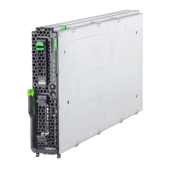
Appendix 12.1 Mechanical overview 12.1.1 Server blade front Figure 107: PRIMERGY BX920 S3 server blade front Pos. Component ID card Y-cable connector Front panel (buttons and indicators) USB connector Upgrade and Maintenance Manual BX920 S3... -
Page 256: Server Blade Interior
Appendix 12.1.2 Server blade interior Figure 108: PRIMERGY BX920 S3 interior Pos. Component UFM (option, on the system board, in the figure below mezzanine card 1) Mezzanine card 1 slot (under the support plate) CPU 1 / Heatsink Memory modules for CPU 2... -
Page 257: Configuration Tables
Appendix 12.2 Configuration tables 12.2.1 Memory configuration table Please refer to chapter "Main memory" on page 163. 12.2.2 Mezzanine card configuration table Please refer to chapter "Population rules for mezzanine cards" on page 124. Upgrade and Maintenance Manual BX920 S3... -
Page 258: Connectors And Indicators
Connector for SAS RAID HDD module Memory modules Connectors for memory modules ROM1 SCU key Connector for ROM1 SCU key USB Dongle Connector for onboard USB port Mezz 2 Connector for mezzanine card 2 Connector for TPM Upgrade and Maintenance Manual BX920 S3... -
Page 259: Onboard Settings
Switch Status Description Switch 1 CMOS clear Switch 2 Clear Password Switch 3 System BIOS recovery / NVRAM clear Switch 4 ME_RCVR (for service personnel only) Default settings: Switch 1 to 4 = Off Upgrade and Maintenance Manual BX920 S3... -
Page 260: Onboard Indicators And Controls
The LEDs C to G are visible from the outside. All other LEDs are only visible if the server blade has been opened. In order to access memory LEDs (B), the air cowls need to be removed (see section "Removing the air cowls" on page 182). Upgrade and Maintenance Manual BX920 S3... - Page 261 SAS RAID HDD module failure Mezzanine card 2 operational Mezzanine card 2 orange on Mezzanine card 2 failure CPU 1 operational CPU 1 orange on CPU 1 failure CPU 2 operational CPU 2 orange on CPU 2 failure Upgrade and Maintenance Manual BX920 S3...
-
Page 262: Connectors And Indicators On The Front
Appendix 12.3.2 Connectors and indicators on the front 12.3.2.1 Front panel connectors Figure 112: Front panel connectors Pos. Component Y-cable port USB connector Upgrade and Maintenance Manual BX920 S3... -
Page 263: Front Panel Indicators
Fabric 2 an active network connection flashing green on Fabric 2 network connection Fabric 1 no network connection green Fabric 1 Fabric 1 an active network connection flashing green on Fabric 1 network connection Upgrade and Maintenance Manual BX920 S3... - Page 264 Server has been switched on and is in flashing standby mode. Power indicator green on Server is switched on. Server is switched off but line voltage is orange on present. yellow on Power supply error. Upgrade and Maintenance Manual BX920 S3...
-
Page 265: Indicators On The Hot-Plug Hdd/Ssd Module
HDD/SSD module is not correctly inserted) – Slow flashing: HDD/SSD Rebuild (the data is being restored after changing a drive) – Fast flashing: HDD/SSD Identify Upgrade and Maintenance Manual BX920 S3... -
Page 266: Minimum Startup Configuration
The minimum startup configuration consists of the following components: Component Notes and reference BX920 S3 server blade Installed in slot CPU 1, see section "Basic 1 CPU with heat sink information" on page 184.