
Related Manuals for MicroNet SP1678A


Summary of Contents for MicroNet SP1678A
- Page 1 User’s Manual 10/100M Management Switch Model No.: SP1678A http://www.micronet.info...
-
Page 2: Table Of Contents
TABLE OF CONTENT INTRODUCTION ..........................................................................ACKAGE ONTENT ......................................EATURES ..................................... HYSICAL ESCRIPTION INSTALLATION ....................................................................... NSTALLATION WITHOUT THE ..................................MOUNT NSTALLATION ................................. NSTALLING ETWORK ABLES ................................. NSTALLATION OF MODULE WEB-BASED USER INTERFACE..................................................................ETTING UP ONNECTION ................................ANAGEMENT VERVIEW ........................................ - Page 3 3.19 Q ............................UALITY OF ERVICE ONFIGURATION 3.19.1 QoS Global Setting................................... 3.19.2 VIP Port Setting ....................................3.19.3 802.1p Setting ....................................3.19.4 D-Type TOS...................................... 3.19.5 T-Type TOS....................................... 3.19.6 R-Type TOS ...................................... 3.19.7 M-Type TOS ..................................... 3.19.8 DSCP Setting....................................3.19.9 Diagnostics ...................................... 3.19.10 Loopback Test....................................
-
Page 4: Introduction
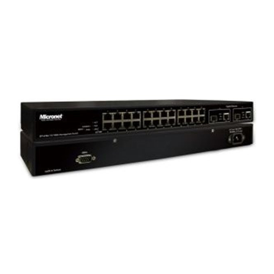
Introduction Micronet SP1678A 10/100M Management Switch delivers wire speed performance and rich layer 2 management functions, suitable for high performance workgroups and server applications. With 24 10/100Mbps RJ-45 ports and 2 Gigabit dual media (RJ-45/SFP) ports, it provides a perfect solution for huge data transmission and preserves the great flexibility of network infrastructure. -
Page 5: Physical Description
1.3 Physical Description SP1678A front view RESET Button It is used to restart the management system only. LEDSET Button LEDSET button is used to change the LED display mode Status Operation System POWER Green Power is on CPURUN Green CPU is activity... -
Page 6: Installation
Installation This switch can be placed directly on your desktop, or mounted in a rack. If you install the device in a normal-standalone standard, the switch is an Intelligent Switch, and users can immediately use most of the features simply by attaching the cables and turning the power on. Before installing the switch, we strongly recommend: 1. -
Page 7: Installation Of Sfp Module
Model Description The switch supports 24 port 10/100M RJ-45 and also 2 Gigabit dual media ports(TP/SFP). Model Port 1~ 26 Configuration 24 Port 10/100M RJ-45 SP1678A 2 Gigabit dual media ports--- TP/SFP fiber 1000BASE-SX mini-GBIC M363A module... - Page 8 Power On The switch supports 100-240 VAC, 50-60 Hz power supply. The power supply will automatically convert the local AC power source to DC power. It does not matter whether any connection plugged into the switch or not when power on, even modules as well. After the power is on, all LED indicators will light up immediately and then all off except the power LED still keeps on.
-
Page 9: Web-Based User Interface
Web-based User Interface 3.1 Setting up Connection This switch can be managed using a standard Web Browser from any computer attached to the network. The SNMP management feature also permits the switch to be managed from any SNMP network management station running a network management program. -
Page 10: Web Management Overview
3.2 Web Management Overview After you login, the switch shows you the system information as a below. This page is default and tells you the basic information of the system, including “Model Name”, “System Description”, “Location”, “Contact”, “Device Name”, “System Up Time”, “Current Time”, “BIOS Version”, “Firmware Version”, “Hardware-Mechanical Version”, “Serial Number”, “Host IP Address”, “Host Mac Address”, “Device Port”, “RAM Size”... -
Page 11: System
On the left-top corner, there is a pull-down list for Auto Logout. For the sake of security, we provide auto-logout function to protect you from illegal user as you are leaving. If you do not choose any selection in Auto Logout list, it means you turn on the Auto Logout function and the system will be logged out automatically when no action on the device 3 minutes later. -
Page 12: Ip Configuration
Hardware-Mechanical version: The version of Hardware and Mechanical. The figure before the hyphen is the version of electronic hardware; the one after the hyphen is the version of mechanical. Series number: The serial number is assigned by the manufacturer. Host IP address: The IP address of the switch. Host MAC address: It is the Ethernet MAC address of the management agent in this switch. -
Page 13: Time Configuration
switch supports DNS client function to re-route the mnemonic name address to DNS server to get its associated IP address for accessing Internet. User can specify a DNS IP address for the switch. With this, the switch can translate a mnemonic name address into an IP address. There are two ways to specify the IP address of DNS. - Page 14 NTP server as well as Time Zone, the switch will sync the time in a short after pressing <Apply> button. Though it synchronizes the time automatically, NTP does not update the time periodically without user’s processing. Time Zone is an offset time off GMT. You have to select the time zone first and then perform time sync via NTP because the switch will combine this time zone offset and updated NTP time to come out the local time, otherwise, you will not able to get the correct time.
-
Page 15: Account Configuration
3.3.4 Account Configuration In this function, only administrator can create, modify or delete the username and password. Administrator can modify other guest identities’ password without confirming the password but it is necessary to modify the administrator-equivalent identity. Guest-equivalent identity can modify his password only. Please note that you must confirm administrator/guest identity in the field of Authorization in advance before configuring the username and password. -
Page 16: Virtual Stack
Parameter description: Name: A name is composed of any letter (A-Z, a-z) and digit (0-9) with maximal 8 characters. VID: The switch supports two kinds of options for managed valid VLAN VID, including “Any” and “Custom”. Default is “Any”. When you choose “Custom”, you can fill in VID number. The valid VID range is 1~4094. -
Page 17: Port Configuration
Parameter description: State: It is used for the activation or de-activation of VSM. Default is Enable. Role: The role that the switch would like to play in virtual stack. Two types of roles, including master and slave are offered for option. Default is Master. Group ID: It is the group identifier (GID) which signs for VSM. - Page 18 Parameter description: Slot No.: Display the slot number. The number is 1 – 3. Port No: Display the port number. The number is 1 – 26. Both port 25 and 26 are optional modules. Media: Show the media type adopted in all ports. The Port 25 and Port 26 are optional modules, which support either fiber or UTP media with either Gigabit Ethernet (1000Mbps) or 10/100Mbps Fast Ethernet port.
- Page 19 Default: Enabled Speed / Duplex Mode: Display the speed and duplex of all port. There are three speeds 10Mbps, 100Mbps and 1000Mbps supported for TP media, and the duplex supported is half duplex and full duplex. If the media is 1Gbps fiber, it is 1000Mbps supported only.
-
Page 20: Configuration
Display the fiber mode, for instance, Multi-Mode, Single-Mode. Tx Central Wavelength: Display the fiber optical transmitting central wavelength, for instance, 850nm, 1310nm, 1550nm and so Baud Rate: Display the maximum baud rate of the fiber module supported, for instance, 10M, 100M, 1G and so on. Vendor OUI: Display the Manufacturer's OUI code which is assigned by IEEE. - Page 21 Parameter description: State: Set the communication capability of the port is enabled or disabled. When enabled, traffic can be transmitted and received via this port. When disabled, the port is blocked and no traffic can be transferred through this port. Port State is configurable by the user. There are only two states “Enable” and “Disable”...
-
Page 22: Port Description
3.4.3 Port Description Port Description is applied to change the setting of each port. In this configuration function, you can give a name to each port. All of them are described in detail below. Fig. 3-12 It is used to set each port’s description. This human readable description can make the port management easier. -
Page 23: Detailed Counter
Parameter description: Tx Byte: Total transmitted bytes. Rx Byte: Total received bytes. Tx Packet: The counting number of the packet transmitted. Rx Packet: The counting number of the packet received. Tx Collision: Number of collisions transmitting frames experienced. Rx Error Packet: Number of bad packets received. 3.4.5 Detailed Counter The function of Detail Counter collects any information and provides the counting about the traffic of the port, no matter the packet is good or bad. -
Page 24: Snmp
Rx 128-255 Bytes: Number of 127 ~ 255-byte frames in good and bad packets received. Rx 256-511 Bytes: Number of 256 ~ 511-byte frames in good and bad packets received. Rx 512-1023 Bytes: Number of 512 ~ 1023-byte frames in good and bad packets received. Rx 1024-Bytes: Number of 1024-max_length-byte frames in good and bad packets received. -
Page 25: Loop Detection
Community name is used as password for authenticating if the requesting network management unit belongs to the same community group. If they both don’t have the same community name, they don’t belong to the same group. Hence, the requesting network management unit can not access the device with different community name via SNMP protocol;... - Page 26 Fig. 3-16 Loop Detection This function will start when you enable looping action by ticking the check box ( ) of the Action. That will create some special packet for looping detection. After enabling looping action, you should decide which port you would like to open loop detection capability.
-
Page 27: Dhcp Boot
3.7 DHCP Boot The DHCP Boot function is used to spread the request broadcast packet into a bigger time frame to prevent the traffic congestion due to broadcast packets from many network devices which may seek its NMS, boot server, DHCP server and many connections predefined when the whole building or block lose the power and then reboot and recover. - Page 28 Parameter description: IGMP snooping mode selection: The switch supports three kinds of IGMP Snooping status, including “Passive”, “Active” and “Disable”. Disable: Set “Disable” mode to disable IGMP Snooping function. Default: Disable Active: In Active mode, IGMP snooping switch will periodically issue the Membership Query message to all hosts attached to it and gather the Membership report message to update the database of the Multicast table.
-
Page 29: Vlan
The Allowed Group function allows the IGMP Snooping to set up the IP multicast table based on user’s specific conditions. IGMP report packets that meet the items you set up will be joined or formed the multicast group. Parameter description: IP Range: The switch supports two kinds of options for managed valid IP range, including “Any”... - Page 30 Tag-based: This is the default setting. Tag-based VLAN identifies its member by VID. This is quite different from port-based VLAN. If there are any more rules in ingress filtering list or egress filtering list, the packet will be screened with more filtering criteria to determine if it can be forwarded.
-
Page 31: Tag-Based Group
3.9.2 Tag-based Group It shows the information of existed Tag-based VLAN Groups. You can also easily create, edit and delete a Tag-based VLAN group by pressing <Add>, <Edit> and <Delete> function buttons. User can add a new VLAN group by inputting a new VLAN name and VLAN ID after pressing <Add> button. Parameter description: VLAN Name: The name defined by administrator is associated with a VLAN group. -
Page 32: Pvid
Add Group: Input the VLAN name, VID and then choose the member by ticking the check box beside the port No. to create a new Tag-based VLAN. As to the parameter of Un-tag, it stands for an egress rule of the port. - Page 33 Parameter description: Port 1-26: Port number. PVID: This PVID range will be 1-4094. Before you set a number x as PVID, you have to create a Tag-based VLAN with VID x. For example, if port x receives an untagged packet, the switch will apply the PVID (assume as VID y) of port x to tag this packet, the packet then will be forwarded as the tagged packet with VID y.
-
Page 34: Port-Based Group
3.9.4 Port-based Group It shows the information of the existed Port-based VLAN Groups. You can easily create, edit and delete a Port-based VLAN group by pressing <Add>, <Edit> and <Delete> function buttons. User can add a new VLAN group by inputting a new VLAN name. Parameter description: VLAN Name: The name defined by administrator is associated with a VLAN group. -
Page 35: Management Vlan
3.9.5 Management VLAN Management VLAN Parameter description: State: It works when the tag-based mode is chosen. When this function is enabled, only the tagged packets with this VID can manage the switch. VID: Valid range 1~4094. 3.10 MAC Table MAC Table Configuration gathers many functions, including MAC Table Information, MAC Table Maintenance, Static and MAC Alias, which cannot be categorized to some function type. -
Page 36: Mac Table Maintenance
Find the entry that meets your setup. Previous Page: Move to the previous page. Next Page: Move to the next page. Alias: The Alias of the searched entry. MAC Address: The MAC address of the searched entry. Port: The port that exists in the searched MAC Entry. VID: VLAN Group that MAC Entry exists. -
Page 37: Static Setting
Learning Limit: To set up the maximum amount of MAC that each port can learn. Valid value of learning limit for port 1~24 ranges from 0-8191. As to port 25~port 26, only the fixed value “8192” is assigned to these two ports and user cannot configure this value. -
Page 38: Mac Alias
hyphens. For example, 00 – 3B- 11 - D6 – 00 - 01 VID: VLAN identifier. This will be filled only when tagged VLAN is applied. Valid range is 1 ~ 4094. Queue: Set up the priority( 0~3) for the MAC. Forwarding Rule: ** Static: A MAC address is assigned to a specific port, all of the switch’s traffics sent to this MAC address... - Page 39 Parameter description: MAC Address: It is a six-byte long Ethernet hardware address and usually expressed by hex and separated by hyphens. For example, 00 – 3B - 11 - D6 – 00 - 02 Alias: MAC alias name you assign. Note: If there are too many MAC addresses learned in the table, we recommend you inputting the MAC address and alias name directly.
-
Page 40: Gvrp
3.11 GVRP GVRP is an application based on Generic Attribute Registration Protocol (GARP), mainly used to automatically and dynamically maintain the group membership information of the VLANs. The GVRP offers the function providing the VLAN registration service through a GARP application. It makes use of GARP Information Declaration (GID) to maintain the ports associated with their attribute database and GARP Information Propagation (GIP) to communicate among switches and end stations. -
Page 41: Gvrp Counter
Default: 1000 unit time. Default Applicant Mode: The mode here means the type of participant. There are two modes, normal participant and non-participant, provided for the user’s choice. Normal: It is Normal Participant. In this mode, the switch participates normally in GARP protocol exchanges. The default setting is Normal. - Page 42 Parameter description: Received: Total GVRP Packets: Total GVRP BPDU is received by the GVRP application. Invalid GVRP Packets: Number of invalid GARP BPDU is received by the GARP application. LeaveAll Message Packets: Number of GARP BPDU with Leave All message is received by the GARP application. JoinEmpty Message Packets: Number of GARP BPDU with Join Empty message is received by the GARP application.
-
Page 43: Group
3.11.3 Group It shows the dynamic group member and their information. Parameter description: VID: VLAN identifier. When GVRP group creates, each dynamic VLAN group owns its VID. Valid range is 1 ~ 4094. Member Port: Those are the members belonging to the same dynamic VLAN group. Edit Administrative Control: When you create GVRP group, you can use Administrative Control function to change Applicant Mode and Registrar Mode of GVRP group member. - Page 44 Parameter description: STP State: Show the current STP Enabled / Disabled status. Default is “Disabled”. Bridge ID: Show switch’s bridge ID which stands for the MAC address of this switch. Bridge Priority: Show this switch’s current bridge priority setting. Default is 32768. Designated Root: Show root bridge ID of this network segment.
-
Page 45: Stp Configuration
3.12.2 STP Configuration User can set the following Spanning Tree parameters to control STP function enable/disable, select mode RSTP/STP and affect STP state machine behavior to send BPDU in this switch. The default setting of Spanning Tree Protocol is “Disable”. Parameter description: Spanning Tree Protocol: Set 802.1W Rapid STP function Enable / Disable. -
Page 46: Stp Port Configuration
The valid value is 4 ~ 30 seconds, default is 15 seconds. Force Version: Two options are offered for the user’s choosing STP algorithm. One is RSTP and the other is STP. If STP is chosen, RSTP will run as a legacy STP. The switch supports RSTP (802.1w) which is backward compatible with STP (802.1d). - Page 47 Configured Path Cost: The range is 0 - 200,000,000. In the switch, if path cost is set to be zero, the STP will get the recommended value resulted from auto-negotiation of the link accordingly and display this value in the field of Path Cost Status.
-
Page 48: Trunk
3.13 Trunk The Port Trunk Configuration is used to configure the settings of Link Aggregation. You can bundle more than one port with the same speed, full duplex and the same MAC to be a single logical port, thus the logical port aggregates the bandwidth of these ports. -
Page 49: Trunk Port Setting/Status
3.13.1 Trunk Port Setting/Status Port setting/status is used to configure the trunk property of each and every port in the switch system. Parameter description: Method: This determines the method a port uses to aggregate with other ports. None: A port does not want to aggregate with any other port should choose this default setting. LACP: A port use LACP as its trunk method to get aggregated with other ports also using LACP. -
Page 50: Aggregation View
trunk group. Status: This field represents the trunk status of a port which uses a trunk method other than “None”. It also represents the management link status of a port which uses the “None” trunk method. “---“ means “not ready” 3.13.2 Aggregation View To display the current port trunk information from the aggregator point of view. -
Page 51: Lacp System Priority
MAC Address: Show the MAC Address part of a system ID. Port: Show the port number part of an LACP port ID. Key: Show the key value of the aggregator. The key value is determined by the LACP protocol entity and can’t be set through management. - Page 52 Supplicant: It is an entity being authenticated by an authenticator. It is used to communicate with the Authenticator PAE (Port Access Entity) by exchanging the authentication message when the Authenticator PAE request to it. Authenticator: An entity facilitates the authentication of the supplicant entity. It controls the state of the port, authorized or unauthorized, according to the result of authentication message exchanged between it and a supplicant PAE.
- Page 53 The figure as above shows the procedure of 802.1x authentication. There are steps for the login based on 802.1x port access control management. The protocol used in the right side is EAPOL and the left side is EAP. At the initial stage, the supplicant A is unauthenticated and a port on switch acting as an authenticator is in unauthorized state.
-
Page 54: Status
connected is in the unauthorized state, the supplicant and the devices connected to this port won’t be allowed to access the network. 10. When the supplicant issue an EAP-Logoff message to Authentication server, the port you are using is set to be unauthorized. Only MultiHost 802.1X is the type of authentication supported in the switch. -
Page 55: Mode
Default: Radius 3.14.2 Mode Set the operation mode of 802.1X for each port. In this device, it supports only Multi-host operation mode. Parameter description: Port Number: Indicate which port is selected to configure the 802.1x operation mode. 802.1x Mode: 802.1x operation mode. There are two options, including Disable and Multi-host mode. Default is Disable. -
Page 56: Param. Setting
Parameter description: Disable Mode: When selecting Disable mode for a port in the function 802.1X Port Mode Configuration, the port is in the uncontrolled port state and does not apply 802.1X authenticator on it. Any node attached on this port can access the network without the admittance of 802.1X authenticator. The Port Status will show the following screen. - Page 57 The controlled port is forced to hold in the authorized state. Auto: The controlled port is set to be in authorized state or unauthorized state depends on the result of the authentication exchange between the authentication server and the supplicant. Default: Auto reAuthMax(1-10): The number of authentication attempt that is permitted before the port becomes unauthorized.
-
Page 58: Alarm
3.15 Alarm 3.15.1 Event The Trap Events Configuration function is used to enable the switch to send out the trap information while pre-defined trap events occurred. The switch offers 24 different trap events to users for switch management. The trap information can be sent out in three ways, including email, mobile phone SMS (short message system) and trap. -
Page 59: Configuration
Note: SMS may not work in your mobile phone system. It is customized for different systems. Parameter description: Email: Mail Server: the IP address of the server transferring your email. Username: your username on the mail server. Password: your password on the mail server. Email Address 1 –... -
Page 60: Save/Restore
Default Configuration: This is the ex-factory setting and cannot be altered. Working Configuration: It is the configuration you are using currently and can be changed any time. The configurations you are using are saved into this configuration file. This is updated each time as you press <Apply> button. User Configuration: It is the configuration file for the specified or backup purposes and can be updated while having confirmed the configuration. -
Page 61: Security
Parameter description: Export File Path: Export Start: Export Save As Start’s config file stored in the flash. Export User-Conf: Export Save As User’s config file stored in the flash. Import File Path: Import Start: Import Save As Start’s config file stored in the flash. Import User-Conf: Import Save As User’s config file stored in the flash. -
Page 62: Isolated Group
Monitored Egress Port: Set up the port for being monitored. It only monitor the packets transmitted by the port you set up. Just tick the check box ( ) beside the port x and valid port is Port 1~26. 3.17.2 Isolated Group Isolated Group function can let the port be independent of other ports in the Isolated group, and the communication is also forbidden between these ports. -
Page 63: Bandwidth Management
3.18 Bandwidth Management 3.18.1 Ingress Bandwidth Setting Ingress Bandwidth setting function is used to set up the limit of Ingress bandwidth for each port. Parameter description: Port No.: Choose the port that you would like this function to work on it. Valid range of the port is 1~26. Rate: Set up the limit of Ingress bandwidth for the port you choose. -
Page 64: Egress Bandwidth Setting
3.18.2 Egress Bandwidth Setting Egress Bandwidth Setting function is used to set up the limit of Egress bandwidth for each port. Parameter description: Port No.: Choose the port that you would like this function to work on it. Valid range of the port is 1~26. Rate: Set up the limit of Egress bandwidth for the port you choose. -
Page 65: Storm Setting
3.18.3 Storm Setting Bandwidth Management function is used to set up the limit of Ingress and Egress bandwidth for each port. Parameter description: Storm Type: Disable: Disable the function of the bandwidth storm control. Broadcast Storm Control: Enable the function of bandwidth storm control for broadcast packets. Multicast Storm Control: Enable the function of bandwidth storm control for multicast packets. -
Page 66: Qos Global Setting
DiffServ DSCP Priority act on DSCP field of IP Header. In the late 1990s, the IETF redefined the meaning of the 8-bit SERVICE TYPE field to accommodate a set of differentiated services (DS). Under the differentiated services interpretation, the first six bits comprise a codepoint, which is sometimes abbreviated DSCP, and the last two bits are left unused. -
Page 67: Vip Port Setting
You can Enable QoS Mode and let QoS function become effective. Default is Disable Priority Control: Just tick the check box ( ) of 802.1P, TOS, or DSCP Qos and click Apply button to be in operation. Scheduling Method: There are two Scheduling Method, WRR and Strict Priority. Default is WRR. After you choose any of Scheduling Method, please click Apply button to be in operation. -
Page 68: Setting
3.19.3 802.1p Setting This function will affect the priority of VLAN tag. Based on priority of VLAN tag, it can arrange 0~8 priorities, priorities can map to 4 queues of the switch (queue 0~3) and possess different bandwidth distribution according to your weight setting. Parameter description: 802.1p Priority Mapping: Each Priority can select any of Queue 0 ~ Queue 3. -
Page 69: T-Type Tos
Parameter description: TOS Delay Priority Mapping: Each Priority can select any of Queue 0 ~ Queue 3. In Default, Priority 0 is mapping to Queue 0, Priority 1 is mapping to Queue 0, Priority 2 is mapping to Queue 1, Priority 3 is mapping to Queue 1, Priority 4 is mapping to Queue 2, Priority 5 is mapping to Queue 2, Priority 6 is mapping to Queue 3, and Priority 0 is mapping to Queue 3. -
Page 70: R-Type Tos
Each Priority can select any of Queue 0 ~ Queue 3. In Default, Priority 0 is mapping to Queue 0, Priority 1 is mapping to Queue 0, Priority 2 is mapping to Queue 1, Priority 3 is mapping to Queue 1, Priority 4 is mapping to Queue 2, Priority 5 is mapping to Queue 2, Priority 6 is mapping to Queue 3, and Priority 0 is mapping to Queue 3. -
Page 71: M-Type Tos
3.19.7 M-Type TOS IP TOS Priority affect TOS fields of IP header, you can find it has 8-bit SERVICE TYPE field that specifies how the datagram should be handled. The field could be divided into six subfields as follows, PRECEDENCE (3 bits), D-Type (Delay Priority, 1 bit ), T-Type (Throughput Priority, 1bit), R-Type (Reliability Priority, 1bit ), M-Type (Monetary Cost Priority, 1bit ), and UNUSED. -
Page 72: Dscp Setting
3.19.8 DSCP Setting In the late 1990s, the IETF redefined the meaning of the 8-bit SERVICE TYPE field to accommodate a set of differentiated services (DS). Under the differentiated services interpretation, the first six bits comprise a codepoint, which is sometimes abbreviated DSCP, and the last two bits are left unused. DSCP can form total 64 (0~63) kinds of Traffic Class based on the arrangement of 6-bit field in DSCP of the IP packet. -
Page 73: Diagnostics
Diagnostics Three functions, including Diagnostics, Loopback Test and Ping Test are contained in this function folder for device self-diagnostics. Each of them will be described in detail orderly in the following sections. 3.19.9 Diagnostics Diagnostics function provides a set of basic system diagnosis. It let users know that whether the system is health or needs to be fixed. -
Page 74: Ping
3.19.11 Ping Ping Test function is a tool for detecting if the target device is alive or not through ICMP protocol which abounds with report messages. The switch provides Ping Test function to let you know that if the target device is available or not. -
Page 75: Firmware Upgrade
Auto Upload Enable: Switch the enabled or disabled status of the auto upload function. Upload Log: Upload log data through tftp. Clear Log: Clear log data. 3.22 Firmware Upgrade The switch supports TFTP upgrade tool for upgrading software. If you assure to upgrade software to a newer version one, you must follow two procedures: Specifying the IP address where TFTP server locates. -
Page 76: Logout
3.24 Logout The switch allows you to logout the system to prevent other users from the system without the permission. If you do not logout and exit the browser, the switch will automatically have you logout. Besides this manually logout and implicit logout, you can pull down the <Auto Logout> list at the left-top corner to explicitly ON/OFF this logout function. -
Page 77: Text-Based User Interface
Text-based User Interface 4.1 Setup the Connection Out-of-band Connection (Console) To activate console port connection, attach a RS-232 cable (Straight-through) to the serial port of a PC running a terminal emulation program and configure the program as follows: Baud rate: 57600 Parity: None... - Page 78 Command instructions reside in the corresponding modes are local commands. The same command with the same command name may occur but perform totally different function in different modes. For example, “show” in IP mode performs displaying the IP information; however, it performs displaying the system information in system mode.
- Page 79 Description: Back to the previous mode. When you enter this command, your current position would move back to the previous mode. If you use this command in the top mode, you are still in the position of the top mode. Argument: None.
- Page 80 Command history: 0. trunk 1. exit 2. FEL2SW-26# trunk 3. FEL2SW-26 (trunk)# exit 4. FEL2SW-26# 5. ? 6. trunk 7. exit 8. alarm 9. events 10. end 11. ip 12. help 13. ip 14. history FEL2SW-26(ip)# history 3 Command history: 13.
- Page 81 4.2.7 save user Syntax: save user Description: To save the current configuration as the user-defined configuration. When you enter this command, the CLI would save your current configuration into the non-volatile FLASH as user-defined configuration. Argument: None. Possible value: None. Example: FEL2SW-26# save user Saving user...
- Page 82 Description: To set up 802.1X status of each port. Argument: <port range> : syntax 1,5-7, available from 1 to 24 <authorized> : Set up the status of each port 0:ForceUnauthorized 1:ForceAuthorized 2:Auto Possible value: <port range> : 1 to 24 <authorized>...
- Page 83 Possible value: <port range> : 1 to 24 <max> : 1-10, default is 2 Example: FEL2SW-26(802.1x)# set reAuthMax 2 2 set reAuthPeriod Syntax: set reAuthPeriod <port-range> <sec> Description: A constant that defines a nonzero number of seconds between periodic reauthentication of the supplicant.
- Page 84 A timer used by the Backend Authentication state machine in order to determine timeout conditions in the exchanges between the Authenticator and the Supplicant or Authentication Server. The initial value of this timer is either suppTimeout or serverTimeout, as determined by the operation of the Backend Authentication state machine.
- Page 85 port 1) port control : Auto reAuthMax txPeriod : 30 Quiet Period : 60 reAuthEnabled : ON reAuthPeriod : 3600 max. Request : 2 suppTimeout : 30 serverTimeout : 30 port 2) port control : Auto reAuthMax txPeriod : 30 Quiet Period : 60 reAuthEnabled : ON reAuthPeriod : 3600...
- Page 86 Description: To create a new guest user. When you create a new guest user, you must type in password and confirm password. Argument: <name>: new account name Possible value: A string must be at least 5 character. Example: FEL2SW-26(account)# add aaaaa Password: Confirm Password: Save Successfully...
- Page 87 Syntax: del <#> Description: The Del here is used to remove the configuration of E-mail address. Argument: <#>: email address number, range: 1 to 6 Possible value: <#>: 1 to 6 Example: FEL2SW-26(alarm-email)# del 2 Syntax: set server <ip> set user <username> set mail-address <#>...
- Page 88 Description: The Del here is used for the de-activation of sms, email and trap event. Argument: <range>:trap number. Possible value: available from 1 to 24. Example: FEL2SW-26(alarm-events)# del sms 1-3 FEL2SW-26(alarm-events)# del email 1-3 FEL2SW-26(alarm-events)# del trap 1-3 FEL2SW-26(alarm-events)# del all 1-3 Syntax: set sms <range>...
- Page 89 show Syntax: show Description: The Show for alarm here is used to display the configuration of Trap, SMS or E-mail. Argument: None. Possible value: None. Example: FEL2SW-26(alarm)# show events FEL2SW-26(alarm)# show email FEL2SW-26(alarm)# show sms <<sms>> Syntax: del <#> Description: The Del here is used to remove the configuration of mobile phone number. Argument: <#>: mobile phone number, range: 1 to 6 Possible value: <#>: 1 to 6 Example:...
- Page 90 Mobile Phone 2: Mobile Phone 3: Mobile Phone 4: Mobile Phone 5: Mobile Phone 6: <<events>> Syntax: del sms <range> del email <range> del trap <range> del all <range> Description: The Del here is used for the de-activation of sms, email and trap event. Argument: <range>:trap number.
- Page 91 8 STP Topology Changed 9 STP Disabled 10 STP Enabled 11 LACP Disabled 12 LACP Enabled 13 LACP Member Added 14 LACP Port Failure 15 GVRP Disabled 16 GVRP Enabled 17 VLAN Disabled 18 Port-based Vlan Enabled 19 Tag-based Vlan Enabled 20 Metro-mode Vlan Enabled 21 Double-tag Vlan Enabled 22 Module Inserted...
- Page 92 Password: Confirm Password: FEL2SW-26(alarm-sms)# set phone-number 1 0968777777 show Syntax: show Description: The Show here is to display the configuration of SMS trap event. Argument: None. Possible value: None. Example: FEL2SW-26(alarm-sms)# show SMS Server : 192.168.1.7 Username Password : **************** Mobile Phone 1: 0968777777 Mobile Phone 2: Mobile Phone 3:...
- Page 93 disable storm-rate Syntax: disable storm-rate <range> Description: To cancel the storm-ate of the port. Argument: <range>:syntax 1,5-7, available from 1 to 24 Possible value: <range>: 1 to 24 Example: FEL2SW-26(bandwidth)# disable storm-rate 1-8 enable egress-rate Syntax: enable egress-rate <range> <data_rate> Description: To set up the egress-rate of the port.
- Page 94 Example: FEL2SW-26(bandwidth)# show Ingress Egress Port ================================================= ====================== All State All Rate Storm State Storm Rate All state All Rate ====== =========== ========== ============= ============ =========== ========== Disabled Disabled Disabled Disabled Disabled Disabled Disabled Disabled Disabled Disabled Disabled Disabled Disabled Disabled Disabled Disabled...
- Page 95 import start Syntax: import start Description: To run the import start function. Argument: None Possible value: None Example: FEL2SW-26(config-file)# import start Import successful. import user-conf Syntax: import user-conf Description: To run the import user-conf function. Argument: None Possible value: None Example: FEL2SW-26(config-file)# import user-conf Import successful.
- Page 96 Description: To set up the delay time for DHCP Boot. Argument: <sec>:range syntax: 0, 1-30. The value “0” is to disable dhcp-boot delay Possible value: <sec>:0-30 Example: FEL2SW-26(dhcp-boot)# set dhcp-boot 30 show Syntax: show Description: To display the status of DHCP Boot. Argument: None Possible value: None Example:...
- Page 97 4.3.9 firmware set upgrade-path Syntax: set upgrade-path <filepath> Description: To set up the image fie that will be upgraded. Argument: <filepath>: upgrade file path Possible value: <filepath>: upgrade file path Example: FEL2SW-26(firmware)# set upgrade-path FEL2SW-26_v2.00.bin.gz show Syntax: show Description: To display the information of tftp server and upgrade-path. Argument: None Possible value: None Example:...
- Page 98 group Syntax: group <group number> Description: To enter any of gvrp group for changing gvrp group setting. You can change the applicant or registrar mode of existing gvrp group per port. Argument: <group number>: enter which gvrp group you had created, using value is vid. Available range: 1 to 4094 Possible value: <group number>: 1~4094 Example: FEL2SW-26(gvrp)# show group...
- Page 99 set applicant Syntax: set applicant <range> <normal|non-participant> Description: To set default applicant mode for each port. Argument: <range>: port range, syntax 1,5-7, available from 1 to 24 <normal>: set applicant as normal mode <non-participant>: set applicant as non-participant mode Possible value: <range>: 1 to 24 <normal|non-participant>: normal or non-participant Example:...
- Page 100 1000 Normal Normal Disable 1000 Normal Normal Disable 1000 Normal Normal Disable set timer Syntax: set timer <range> <join> <leave> <leaveall> Description: To set gvrp join time, leave time, and leaveall time for each port. Argument: <range> : port range, syntax 1,5-7, available from 1 to 24 <join>: join timer, available from 20 to 100 <leave>: leave timer, available from 60 to 300 <leaveall>: leaveall timer, available from 1000 to 5000...
- Page 101 GVRP Counter port: 2 Counter Name Received Transmitted -------------------- -------- ----------- Total GVRP Packets Invalid GVRP Packets ---- LeaveAll message JoinEmpty message JoinIn message LeaveEmpty message Empty message show group Syntax: show group Description: To show the gvrp group. Argument: none Possible value: none Example: FEL2SW-26(gvrp)# show group...
- Page 102 IP Multicast: 1) IP Address : 224.1.1.1 VLAN ID Member Port: 22 4.3.13 disable dhcp Syntax: disable dhcp Description: To disable the DHCP function of the system. Argument: None Possible value: None Example: FEL2SW-26(ip)# disable dhcp : Disabled system DHCP function. enable dhcp Syntax: enable dhcp <manual|auto>...
- Page 103 show Syntax: show Description: To display the system’s DHCP function state, IP address, subnet mask, default gateway, DNS mode, DNS server IP address and current IP address. Argument: None Possible value: None Example: FEL2SW-26(ip)# show DHCP : Disable IP Address : 192.168.2.65 Subnet mask : 255.255.255.0...
- Page 104 Argument: None. Possible value: None. Example: FEL2SW-26(log)# show Tftp Server : 0.0.0.0 Auto Upload : Disable 1) Wed Apr 13 12:13:27 2005 Link Up [Port 1] 2) Wed Apr 13 12:13:26 2005 Link Down [Port 1] 3) Wed Apr 13 11:58:31 2005 Login [admin] 4) Wed Apr 13 11:19:45 2005 Login [admin] 5) Wed Apr 13 11:19:37 2005 Logout [admin] upload...
- Page 105 FEL2SW-26(mac-table-alias)# show MAC Alias List MAC Address Alias ----- ----------------- ---------------- 00-02-03-04-05-06 aaa 00-33-03-04-05-06 ccc 00-44-33-44-55-44 www <<information>> search Syntax: search <port> <mac> <vid> Description: To look for the relative mac information in mac table. Argument: <port> : set up the range of the ports to search for, syntax 1,5-7, available form 1 to 24 <mac>...
- Page 106 Possible value: None Example: FEL2SW-26(mac-table-maintain)# set flush FEL2SW-26(mac-table-maintain)# show Syntax: show Description: To display the settings of age-timer. Argument: None Possible value: None Example: FEL2SW-26(mac-table-maintain)# show age-timer : 300 seconds FEL2SW-26(mac-table-maintain)# <<static-mac>> Syntax: add <mac> <port> <vid> [alias] Description: To add the static mac entry. Argument: <mac>...
- Page 107 Possible value: None Example: FEL2SW-26(mac-table-static-mac)# show filter Static Filtering Etnry: (Total 1 item(s)) 1) mac: 00-33-03-04-05-06, vid: -, alias: ccc FEL2SW-26(mac-table-static-mac)# show forward Syntax: show forward Description: To display the static forward table. Argument: None Possible value: None Example: FEL2SW-26(mac-table-static-mac)# show forward Static Forwarding Etnry: (Total 1 item(s)) 1) mac: 00-02-03-04-05-06, port: 3, vid: -, alias: aaa...
- Page 108 delete Syntax: delete # Description: To delete a specific record or range. Argument: <#>: a specific or range management security entry(s) Possible value: none Example: FEL2SW-26(management)# show #: 1 Name : Tom VlanID : 2 IP : 192.168.1.30-192.168.1.80 Type : SNMP Action : Deny Port : 1,2 FEL2SW-26(management)# delete 1...
- Page 109 Description: To show the specific management policy record. Argument: none Possible value: none Example: FEL2SW-26(management)# show #: 1 Name : Tom VlanID : 2 IP : 192.168.1.30-192.168.1.80 Type : SNMP Action : Deny Port : 1,2 4.3.17 max-pkt-len set len Syntax: set len <range>...
- Page 110 1532 1532 1532 1532 1532 4.3.18 mirror set mirror-mode Syntax: set mirror-mode <rx|disable> Description: To set up the mode of Mirror (rx mode or disable). Argument: <rx | disable>: rx : Enable the mode of Mirror(Only mirror the packets that is received) disable: End the function of mirror Possible value: <rx | disable>: rx or disable Example:...
- Page 111 Possible value: None Example: FEL2SW-26(mirror)# show Mirror Mode : rx Monitoring Port : 2 Monitored Port : 3 4 5 7 10 FEL2SW-26(mirror)# 4.3.19 port clear counter Syntax: clear counter Description: To clear all ports’ counter (include simple and detail port counter) information. Argument: None Possible value: None Example:...
- Page 112 set speed-duplex Syntax: set speed-duplex <range> <auto|10half|10full|100half|100full|1Gfull> Description: To set up the speed and duplex of all ports. Argument: <range>:syntax 1,5-7, available from 1 to 24 <port-speed>: auto: set auto-negotiation mode 10half: set speed/duplex 10M Half 10full: set speed/duplex 10M Full 100half: set speed/duplex 100M Half 100full: set speed/duplex 100M Full 1Gfull: set speed/duplex 1G Full.
- Page 113 show status Syntax: show status Description: To display the port’s current status. Argument: None Possible value: None Example: FEL2SW-26 (port)# show status 4.3.20 set advance-layer4 Syntax: set advance-layer4 <port-range> <#> <tcp/udp port> <default> <match> Description: To set class of ports on advanced mode of Layer 4 qos. Argument: <port-range>: port range, syntax: 1,5-7, available from 1 to 24 <#>: special UDP/TCP port selection, range: 1-10...
- Page 114 set diffserv Syntax: set diffserv <ds-range> <class> Description: To set class of ports on IP DiffServe qos. Argument: <ds-range>: dscp field, syntax 1,5-7, available from 0 to 63 <class>: class of service setting. 1: high, 0: low Possible value: <ds-range>: 0 to 63 <class>: 1or 0 Example: FEL2SW-26(qos)# set diffserv 0-20 1...
- Page 115 FEL2SW-26(qos)# set pri-tag 1-15 1-2 1 set simple-layer4 Syntax: set simple-layer4 <#> Description: To set class of ports on simple mode of Layer 4 qos. Argument: <#>: layer-4 configuration mode, valid values are as follows: 0: disable ip tcp/udp port classification 1: down prioritize web browsing, e-mail, FTP and news 2: prioritize ip telephony (VoIP) 3: prioritize iSCSI...
- Page 116 high high high high high high high high high high high high high high high high high high high high high high high high high high high high high high high high 4.3.21 reboot reboot Syntax: reboot Description: To reboot the system. Argument: None Possible value: None Example:...
- Page 117 Description: The Set here is used for the setup of get-community, set-community, trap host ip, host port and trap-community. Argument: <#>: trap number <ip>: ip address or domain name <port>: trap port <community>:trap community name Possible value: <#>: 1 to 6 <port>:1~65535 Example: FEL2SW-26(snmp)# set get-community public...
- Page 118 Example: FEL2SW-26(stp)# disable enable Syntax: enable Description: To enable the STP function. Argument: None Possible value: None Example: FEL2SW-26(stp)# enable set config Syntax: set config <Bridge Priority> <Hello Time> <Max. Age> <Forward Delay> Description: To set up the parameters of STP. Argument: <Bridge Priority>:priority must be a multiple of 4096,available from 0 to 61440.
- Page 119 Argument: <stp|rstp>:stp / rstp Possible value: <stp|rstp>:stp / rstp Example: FEL2SW-26(stp)# set version rstp show config Syntax: show config Description: To display the configuration of STP. Argument: None Possible value: None Example: FEL2SW-26(stp)# show config STP State Configuration Spanning Tree Protocol : Enabled Bridge Priority (0-61440) : 61440...
- Page 120 show status Syntax: show status Description: To display the status of STP. Argument: None Possible value: None Example: FEL2SW-26(stp)# show status STP Status : STP State : Enabled Bridge ID : 00:11:3B:D8:09:1D Bridge Priority : 61440 Designated Root : 00:11:3B:D8:09:1D Designated Priority : 61440 Root Port...
- Page 121 Argument: None Possible value: None Example: FEL2SW-26(system)# show Model Name : FEL2SW-26 System Description : L2 Managed Switch Location Contact Device Name : FEL2SW-26 System Up Time : 0 Days 1 Hours 19 Mins 17 Secs Current Time : Fri Nov 13 01:26:11 2004 BIOS Version : v1.00 Firmware Version...
- Page 122 : daylight saving end Month (01-12) : daylight saving end Day (01-31) : daylight saving end Hour (00-23) Possible value: : -5 to +5 : (01-12) : (01-31) : (00-23) : (01-12) : (01-31) : (00-23) Example: FEL2SW-26(time)# set daylightsaving 3 10/12/01 11/12/01 Save Successfully FEL2SW-26(time)# set manual...
- Page 123 Example: FEL2SW-26(time)# show Current Time : Thu Thu 14 15:04:03 2005 NTP Server : 209.81.9.7 Timezone : GMT+8:00 Day light Saving : 0 Hours Day light Saving Start : Mth: 1 Day: 1 Hour: 0 Day light Saving End : Mth: 1 Day: 1 Hour: 0 FEL2SW-26(time)# 4.3.25 trunk...
- Page 124 Argument: None Possible value: None Example: FEL2SW-26(trunk)# show aggtr-view Aggregator 1) Method: None Member Ports: 1 Ready Ports:1 Aggregator 2) Method: LACP Member Ports: 2 Ready Ports: show lacp-detail Syntax: show lacp-detail <aggtr> Description: To display the detailed information of the LACP trunk group. Argument: <aggtr>: aggregator, available from 1 to 24 Possible value: <aggtr>: 1 to 24 Example:...
- Page 125 LACP Active LACP Active LACP Active LACP Active LACP Active None Active None Active None Active None Active None Active None Active 4.3.26 vlan del port-group <name> Syntax: del port-group <name> Description: To delete the port-based vlan group. Argument: <name>: which vlan group you want to delete. Possible value: <name>: port-vlan name Example: FEL2SW-26(vlan)# del port-group VLAN-2...
- Page 126 Argument: <range>: which port(s) you want to set, syntax 1,5-7, available from 1 to 24 Possible value: <range>: 1 to 24 Example: FEL2SW-26(vlan)# enable drop-untag 5-10 enable sym-vlan <range> Syntax: enable sym-vlan <range> Description: To drop frames from the non-member port. Argument: <range>: which port(s) you want to set, syntax 1,5-7, available from 1 to 24 Possible value: <range>: 1 to 24 Example:...
- Page 127 <range>: 1 to 24 <vid>: 1 to 4094 Example: FEL2SW-26(vlan)# set port-role 5 hybrid 6 set pvid Syntax: set pvid <range> <pvid> Description: To set the pvid of vlan. Argument: <range>: which port(s) you want to set PVID(s), syntax 1,5-7, available from 1 to 24 syntax: 1,5-7 <pvid>: which PVID(s) you want to set, available from 1 to 4094 Possible value: <range>: 1 to 24...
- Page 128 1) Vlan Name : default Vlan ID Sym-vlan : Disable Member : 1 2 3 4 5 6 7 8 9 10 11 12 13 14 15 16 2) Vlan Name : VLAN-2 Vlan ID Sym-vlan : Disable Member : 2 3 4 5 6 13 14 15 FEL2SW-26(vlan)# show pvid Syntax: show pvid...
- Page 129 set gid Syntax: set gid <gid> Description: To set the group id. Argument: <gid>:Group ID Possible value: <gid>:a-z,A-Z,0-9 Example: FEL2SW-26(vs)# set gid group1 set role Syntax: set role <master|slave> Description: To set role. Argument: <master|slave>: master: act as master, slave: act as slave Possible value: <master|slave>: master or slave Example: FEL2SW-26(vs)# set role master...
-
Page 130: Specification
Specification IEEE Standards IEEE802.3, 10BASE-T IEEE802.3u, 100BASE-TX IEEE802.3ab, 1000BASE-T IEEE802.3z, 1000BASE-LX/SX IEEE802.3x, Flow control IEEE802.1q, Tag-based VLAN IEEE802.1p, Traffic prioritization (CoS) IEEE802.1d, Spanning Tree Protocol IEEE 802.1w Rapid Spanning Trees IEEE802.1x network access control Hardware Packet Buffer 256KBytes 128KB control memory &... - Page 131 Security IEEE802.1x access control Limit number of MAC addresses learned per port static MAC addresses stay in the filtering table. Management Web-based, Telnet, Console, SNMP, Virtual Stacking. TFTP software-upgrade. MIB-2 (RFC 1213) MIBs Supported - Interface MIB - Address Translation MIB - IP MIB - ICMP MIB - TCP MIB...
Need help?
Do you have a question about the SP1678A and is the answer not in the manual?
Questions and answers