Advertisement
Quick Links
INSTALLATION
INSTRUCTIONS
PARTS LIST
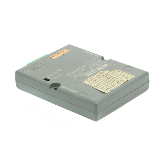
Security System (sold separately):
P/N 08E51-S01-101F
Control unit
Owner's Manual
(discard)
2 Washer-screws
(not used)
Relay 4-pin
Relay 5-pin
2 Fuses (3A)
2 Long wire ties
Card
(not used)
2 Decals
Fuse box label
© 1999 American Honda Motor Co., Inc - All Rights Reserved.
www.collegehillshonda.com/parts
Accessory
SECURITY SYSTEM
AII 20465 (9908)
Y0540-B
Application
2000 CIVIC
4-DOOR
(LX/EX/VP MODELS ONLY)
Remote Transmitter (sold separately):
P/N 08E61-S01-101
(Required for LX model only)
2 Transmitters
Owner's Manual
Security Attachment (sold separately):
P/N 08E55-S01-100H
Control unit bracket
LED
Disarm switch
Push nut (for LED)
2-Pin connector
Publications No.
AII 20469
Issue Date
AUG 1999
1 of 8
08E55-S01-1H00-91
Advertisement

Related Manuals for Honda 08E55-S01-100H


Summary of Contents for Honda 08E55-S01-100H
- Page 1 (LX/EX/VP MODELS ONLY) Remote Transmitter (sold separately): P/N 08E61-S01-101 (Required for LX model only) 2 Transmitters Owner’s Manual Security Attachment (sold separately): P/N 08E55-S01-100H Control unit bracket Disarm switch Push nut (for LED) 2-Pin connector AII 20465 (9908) Y0540-B Application Publications No.
-
Page 2: Installation
3-Pin connector Washer Owner’s Manual Cushion tape 2 Collars Flange bolt, 6 x 12 mm 2 Bolts, 4 x 30 mm Wire tie 4 Short wire ties (white) Resistor TOOLS AND SUPPLIES REQUIRED Phillips screwdriver Stubby Phillips screwdriver Drill Eye protection (face shield, safety goggles, etc.) 5.5 mm and 12 mm Drill bits Tape measure 10 mm and 12 mm Sockets... - Page 3 Remove the driver's dashboard lower cover: • Remove the three screws. • Gently pull along the top to release the three retaining clips. • Unplug the connector(s) and remove the cover. DRIVER'S DASHBOARD LOWER COVER MOONROOF MODEL Remove the knee bolster (two bolts). KNEE BOLSTER ©...
- Page 4 Intalling the LED Measure and mark the upper steering column cover removed in step 7, and lightly center-punch the mark. While wearing eye protection, drill a 5.5 mm hole through the center-punched mark. Remove all burrs. 5.5 mm DRILL CENTER OF COLUMN COVER 30 mm MARK...
- Page 5 13. Route the terminal ends of the disarm switch harness through the 12 mm hole you just drilled in the dashboard lower cover. Secure the disarm switch on the dashboard lower cover using the 12 mm and washer provided. Tighten the nut securely. DASHBOARD LOWER COVER DISARM SWITCH...
- Page 6 18. Position the control unit on the control bracket, and install the two collars and two 4 x 30 mm bolts. CONTROL UNIT 19. Locate the 22-pin connector blue-taped to the vehicle harness, and remove the blue tape to free the connector.
- Page 7 23. Locate the 4-pin and 6-pin connectors blue-taped to the vehicle harness behind the fuse box. 24. Locate the 4-pin connector blue-taped to the vehicle harness above the fuse box, and remove the tape to free the connector. Plug the 4-pin relay into the 4-pin connector you just freed, then secure the relay to the vehicle harness with the wire tie.
- Page 8 29. Behind the left side of the fuse box, locate the 3-pin connector blue-taped to the vehicle harness, and remove the blue tape to free the connector. Plug the 3-pin connector you just freed into the 3-pin connector from the disarm switch. VEHICLE HARNESS 3-PIN CONNECTOR FUSE BOX...