
Related Manuals for Clarke air INDY OIL FREE


Summary of Contents for Clarke air INDY OIL FREE
- Page 1 INDY OIL FREE INDY OIL FREE AIR COMPRESSOR AIR COMPRESSOR OPERATION & MAINTENANCE INSTRUCTIONS 009050502 Serial/Batch No: .......
- Page 2 THIS PAGE LEFT INTENTIONALLY BLANK Please note that the details and specifications contained herein are correct at the time of going to print. However CLARKE International reserve the right to change specifications at any time without prior notice. Always consult the machines data plate...
- Page 3 INDY AIR COMPRESSOR Thank you for purchasing this Clarke Indy Air Compressor. Before attempting to operate the machine, please read this instruction manual thoroughly and carefully follow all directions given. This is for your own safety and that of others around you, and also to help you achieve long and trouble free service from your compressor.
-
Page 4: Safety Precautions
Never direct a jet of compressed air at people or animals, or spray paint towards people or animals. Gasket Pressure Gauge • Use appropriate protective equipment, such as Clarke safety- Valve Disk goggles or glasses, dust masks, ear defenders etc. when using compressed air tools. -
Page 5: Electrical Connections
Electrical Connections PARTS DIAGRAM (Compressor) 230 Volt models: Connect the mains lead to a standard 230 Volt (50Hz) electrical supply through an approved BS1363, 13amp plug or a suitably fused isolator switch. 110 Volt models: Connect the mains lead to a suitable 110 Volt (50Hz) electrical supply through an approved plug or a suitably fused isolator switch. - Page 6 OPERATION PARTS LIST (JS Spraygun) (Numbers in brackets refer to fig 1. Page 6) Item No Description Check that the mains voltage corresponds to that shown on the Air Cap Ring data sticker on the crankcase cover (5). Ensure that the on/off switch (4) is set to off, position ‘O’ and all air Air Cap is expelled from the compressor by opening the outlet tap (3).
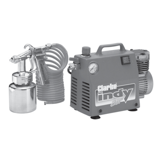
- Page 7 PARTS DIAGRAM (JS Spraygun) INDY SPRAY OUTFIT 1. Pressure regulator knob. 6. Mains Lead. 2. Pressure gauge. (not shown) 3. Air outlet tap. 7. Recoil air hose. 4. On/Off switch. 8. JS Spraygun. 5. Crank case cover. -14 - - 7 -...
- Page 8 PAINT SPRAYING HINTS TECHNICAL DATA WARNING Model Indy Air - (Oil Free) NEVER attempt to spray unless you are wearing suitable, approved Maximum Air Pressure 115 PSI respiratory and eye protection. REMEMBER that some modern paints require specialist respiratory Air Displacement 3.5 CFM protection...always consult the paint manufacturers instructions.
- Page 9 PAINT SPRAYING HINTS Cont FAULT FINDING With considerate use, your CLARKE Air Compressor should provide you with long PAINT THINNING and trouble free service. Routine checks should be made on both the electrical supply as well as the compressed air lines and connections. If any fault appears, the reason for which is not immediately obvious, please contact your local For a professional looking finish paint must be thinned.
- Page 10 PAINT SPRAYING HINTS Cont ROUTINE MAINTENANCE IMPORTANT Before attempting to service or carry out any maintenance or repairs on your Indy air compressor, always ensure that the unit is disconnected from the main electrical supply, i.e. mains plug removed, also ensure that all air has been expelled from the cylinder head.
Need help?
Do you have a question about the air INDY OIL FREE and is the answer not in the manual?
Questions and answers