Brother Z-8550A Service Manual
Electronic direct drive zigzag lock stitcher with thread trimmer
Hide thumbs
Also See for Z-8550A:
- Instruction manual (90 pages) ,
- Parts book (70 pages) ,
- Brochure & specs (6 pages)

Related Manuals for Brother Z-8550A


Summary of Contents for Brother Z-8550A
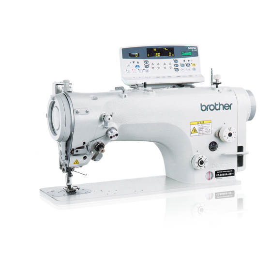
- Page 1 Z-8550A SERVICE MANUAL Z-8560A Please read this manual before making any adjustments. ELECTRONIC DIRECT DRIVE ZIGZAG LOCK STITCHER ELECTRONIC DIRECT DRIVE ZIGZAG LOCK STITCHER WITH THREAD TRIMMER...
- Page 2 This service manual is intended for Z-8550A, Z-8560A; be sure to read the Z-8550A, Z-8560A instruction manual before this manual. Carefully read the “SAFETY INSTRUCTIONS” and the whole of this manual to understand this product before you start maintenance. As a result of research and improvements regarding this product, some details of this manual may not be the same as those for the product you purchased.
-
Page 3: Safety Instructions
) indicates something that you must do. The picture inside the circle indicates the · · · · · nature of the thing that must be done. (For example, the symbol at left means “you must make the ground connection”.) Z-8550A, 8560A... - Page 4 Contact your Brother dealer or a qualified shocks could occur. electrician for any electrical work that may need to be done.
- Page 5 If an error occurs in machine, or if abnormal noises or smells are noticed, immediately turn off the If the actuator is pressed by mistake when using the power switch. Then contact your nearest Brother correction sewing function, the needle will move in a dealer or a qualified technician.
-
Page 6: Maintenance And Inspection
The following warning labels appear on the sewing machine. Please follow the instructions on the labels at all times when using the machine. If the labels have been removed or are difficult to read, please contact your nearest Brother dealer. Safety devices:... - Page 7 Do not touch the thread takeup or the knife, otherwise injury may result. Oil pan 3316M (For Europe) 3317M Z-8550A, 8560A...
-
Page 8: Table Of Contents
..........29 4-8-2. Restoring the control program if an error CHANGING THE FEED AMOUNT TO LONG occurs during version updating ..... 30 STITCH SPECIFICATIONS 4-9. Writing error log data to CF cards ....31 ......(from 2.0mm to 5.0mm) Z-8550A, 8560A... - Page 9 (8560A only) ......83 16. SEGMENT DISPLAY DEFINITION 9-24. Adjusting the thread wiper (8560A only, optional device) ......84 TABLE ..........10. APPLYING GREASE (When “GrEASEUP” appears)....10-1. To continue sewing temporarily without applying grease ..........85 Z-8550A, 8560A...
-
Page 10: Machine Specifications
*4… The maximum number of custom-made patterns that can be stored is 99 patterns with a total of 49,500 stitches, at 500 stitches or less per pattern. (Custom patterns can be created using the PS-300B (option device) and are saved into the control box using commercially-available CF cards. Ask the place of purchase for details.) Z-8550A, 8560A... -
Page 11: Sewing Pattern
1 to 99 stitches. Blind stitch (right) (No. of stitches) 1430M Sewing patterns created using PS-300B (optional device) can be sewn. Custom made pattern (The pattern number is set in the columns marked with 3320M-3333M 3334M-3348M Z-8550A, 8560A... -
Page 12: Function Settings
• If the memory switch number is changed after the setting value has been changed but before the ENTER key is pressed, the setting value will not be changed. Press the ENTER key for each memory switch number to accept the setting values. Z-8550A, 8560A... -
Page 13: List Of Memory Switch Settings
1: Thread trimming switch Deceleration stop control when treadle is returned to neutral position 0 - 1 0: Deceleration stop control without single stitch advance 1: Above control is not carried out Z-8550A, 8560A... - Page 14 (if No. 31 is set to “0”, sewing starts again when the treadle is depressed slghtly 2246M Delay time for motor to start when presser foot is lifted and sewing machine 150 (ms) 0 - 500 (ms) starts operating when automatic presser foot lifting is being used Z-8550A, 8560A...
- Page 15 Delay time for motor to start when standing operation pedal turns on. Operation during standing operation when AUTO function is on 0: Sewing stops before finished when presser lifter pedal turns on 0 - 1 (momentary stop operation) 1: Above function is disabled Z-8550A, 8560A...
- Page 16 (When No. 58 is set to “1”) 0 (ms) 0 - 150 (ms) Presser foot lifting 0 (ms) 0 - 99 (ms) (Fully on) 2247M * : Settings indicated with * are enabled after the power is turned off and then back on again. Z-8550A, 8560A...
- Page 17 • When set to positive (+) settings with the initial values as a reference, the quick reverse solenoid ON/OFF timing will become slower. If the seams are too short immediately after changing occurs, change the setting in the (+) direction. Z-8550A, 8560A...
- Page 18 2258M (Ex. 2) No. 83 setting Sewing speed Treadle backward Neutral Treadle forward 2259M depression stroke depression stroke (Ex. 3) No. 85 setting Sewing speed Treadle backward Neutral Treadle forward 2260M depression stroke depression stroke Z-8550A, 8560A...
- Page 19 *1: Setting is read from machine head detection switch. *2: This is the upper limit setting for the maximum sewing speed. Refer to “7-6. Setting the maximum sewing spped” of the instruction manual for details on the maximum sewing speed settings. Z-8550A, 8560A...
- Page 20 Correction level when 2-step zigzag direction is reversed (“0” means no 0 - 2 correction) * Enabled when zigzag width setting is 4.1, 4.3, … 30 - 90 45 (degrees) Servo lock release rotation angle [Do not change this setting.] (degrees) Z-8550A, 8560A...
- Page 21 Needle zigzag sync position (angle from needle up stop signal turning off x 8 4 - 14 degrees) 0 - 5 Needle zigzag sync delay (degrees) Machine head fan 0: Stopped 0 - 1 1: Operating (stops when machine head is tilted back and when an error occurs) Z-8550A, 8560A...
- Page 22 The following memory switch numbers are used for displaying maintenance information. Explanation of display details Cumulative power on time (Actual time = Displayed time x 10 hours) Cumulative running time (Actual time = Display xxxx x 10 hours) ROM version (x.xxx) Z-8550A, 8560A...
-
Page 23: Data Initialization
While holding down the MAX key on the operation panel, turn on the power switch (1). Orange display 0170B Green display The speed data will be set to the speed data for the machine head detection unit. After this, operation panel and treadle operation will be possible. 0171B Z-8550A, 8560A... - Page 24 * If there is no custom pattern data in the internal memory, the buzzer will sound twice. 0175B Deleting all custom pattern data Press and hold the RESET key. After this, press the ENTER key. The initial display will appear. Z-8550A, 8560A...
-
Page 25: When Data Is Initialized Automatically
After the initialization is complete, “iniT rPM” will appear in green in the main display. After this, operation panel and treadle operation will be possible. Z-8550A, 8560A... -
Page 26: Error History Checking Method
* The last seven digits (3) show the time stamp (1 hour). The time displayed is the cumulative time since the power was turned on. 0179B To return to the normal operating mode Set the power switch (1) to OFF. 0180B Z-8550A, 8560A... -
Page 27: Error History Display Examples
* The programs indicated by the symbols (2) are as follows. Symbol (2) Program Main program 2 MT Motor program 3 PL Panel program 4 iP IPL program 0182B When the TEST key is pressed, the mode returns to normal operation mode. 0183B Z-8550A, 8560A... -
Page 28: Checking Input And Output
Machine head tilt detection When the machine head is tilted back, the TEST icon Switch TEST icon Switch - ON turns ON. When the knee switch is pressed, the slow start icon Knee switch - ON Slow start icon turns ON. Z-8550A, 8560A... - Page 29 Thread trimmer solenoid operates. Continuous backtack key Thread wiper solenoid operates. Start backtack key Quick reverse solenoid operates. Fixed stitch/name label key Presser foot solenoid operates. P1 key Upper thread feeding solenoid operates. P2 key Option solenoid operates. Z-8550A, 8560A...
-
Page 30: Dip Switch Setting Method
(*3) When set to ON, treadle operation is disabled, so it should always be set to OFF. If it is set to ON, [DIP SW4] (green) and [Err 101] (orange) will appear alternately in the main display of the operation panel. Z-8550A, 8560A... -
Page 31: Needle Zigzag Home Position Adjustment Procedure
The setting will be written to the machine head memory and adjustment mode will be exited. 0183B NOTE: If the TEST key is pressed while [orG] is flashing, [Err 202] will appear. Press the TEST key once more to exit adjustment mode. Repeat the procedure from step 3. Z-8550A, 8560A... -
Page 32: Using Cf Cards
However, no TM or other similar symbols appear in the main text of this manual. 4-2. Structure of a CF card folder \BROTHER\ISM\ISMSYS\ISM04MN.MOT : Control program \BROTHER\ISM\ISMDD00\ISMMSW.SEW : Memory switch data \ISMHST.SEW : Error log data \ISMS0901.SEW : Additional sewing data P No. = 91 \ISMS0902.SEW : Additional sewing data P No. -
Page 33: Preparation For Reading/Writing Data
Control programs are read from the CF card and used to update the firmware version. [LoG-] Error log data is written from the sewing machine to the CF card. * The additional sewing data that can be use with this sewing machine is data that has been created for the Z-8550A/Z-8560A. Z-8550A, 8560A... -
Page 34: Reading Additional Sewing Data Into The Sewing Machine
When [End] is displayed, the process is complete. Reading complete 0194B Press the TEST key to exit read/write mode. 0195B Set the power switch (1) to OFF and remove the CF card. 0196B Z-8550A, 8560A... -
Page 35: Writing Additional Sewing Data To Cf Cards
CF card. When [End] is displayed, the process is complete. Writing complete 0194B Press the TEST key to exit read/write mode. 0195B Set the power switch (1) to OFF and remove the CF card. 0196B Z-8550A, 8560A... -
Page 36: Reading Memory Switch Data Into The Sewing Machine
The buzzer will sound and the memory switch data will be loaded from the CF card and copied into the sewing machine's internal memory. Reading Finished when [End] is displayed. 0203B Set the power switch (1) to OFF and remove the CF card. 0196B Z-8550A, 8560A... -
Page 37: Writing Memory Switch Data To A Cf Card
The buzzer will sound and the memory switch data will be copied from the internal memory onto the CF card. Writing Writing complete 0205B Press the TEST key to exit read/write mode. 0195B Set the power switch (1) to OFF and remove the CF card. 0196B Z-8550A, 8560A... -
Page 38: Updating The Control Program Version
* Never remove the CF card or turn off the power switch while reading of the CF card is in progress. 0208B * If the filename and folder name for the control program are incorrect, error [Err 421] will be displayed. Set the power switch (1) to OFF and remove the CF card. 0196B Z-8550A, 8560A... -
Page 39: Restoring The Control Program If An Error Occurs During Version Updating
The operation panel will switch off and the version updating will be carried out. When the power turns back on, the updating is complete. 0216B Set the power switch (1) to OFF and remove the CF card. 0196B Z-8550A, 8560A... -
Page 40: Writing Error Log Data To Cf Cards
The buzzer will sound and the error log data will be copied from the internal memory onto the CF card. Writing Writing complete 0210B Press the TEST key to exit read/write mode. 0195B Set the power switch (1) to OFF and remove the CF card. 0196B Z-8550A, 8560A... -
Page 41: Mechanical Descriptions
5-1. Needle bar and thread take-up mechanisms 1109B 1. Motor 2. Upper shaft <2> Pulley 3. Thread take-up crank 4. Needle bar connecting rod shaft 5. Needle bar connecting rod [5] Rotary thread take-up lever 6. Needle bar clamp 7. Needle bar Z-8550A, 8560A... -
Page 42: Lower Shaft And Shuttle Race Mechanisms
4. Timing belt 5. Timing pulley D 6. Lower shaft 7. Bevel gear 8. Bevel gear 9. Rotary hook driving shaft 10. Timing pulley 39 11. Timing belt 12. Timing pulley 26 13. Rotary hook shaft 14. Rotary hook Z-8550A, 8560A... -
Page 43: Zigzag Mechanism
5. MECHANICAL DESCRIPTIONS 5-3. Zigzag mechanism 1. Pulse motor 2. Motor lever 3. Zigzag connecting rod 4. Zigzag joint 5. Needle bar base 1110B 6. Needle bar Z-8550A, 8560A... -
Page 44: Presser Foot Mechanism
2. Knee lifter shaft 3. Knee lifter complying bar assembly 4. Knee lifter bar 5. Knee lifter lever 6. Knee lifter connecting rod 7. Presser bar lifter lever 8. Presser bar bracket 9. Presser bar 10. Presser foot 1112B Z-8550A, 8560A... - Page 45 1. Lifting lever 2. Presser bar lifter lever 3. Presser bar bracket 4. Presser bar 5. Presser foot 1113B <For options> 1. Presser foot lifter solenoid set 2. Knee lifter shaft L 3. Knee lifter complying bar assembly 0079B Z-8550A, 8560A...
-
Page 46: Feed Mechanism
4. Side connecting rod 5. Feed rocker arm 6. Feed rocker shaft (1) Feed regulator [Up/down movement] 1115B 1. Lower shaft 2. Lower shaft tip (eccentricity) 3. Feed lifting link 4. Feed bar 5. Feed dog (up/down movement) Z-8550A, 8560A... - Page 47 (1) Feed regulator 0084B (2) Side connecting rod (3) Feed driving connecting rod (4) Feed rocker arm Changing the angle of the feed regulator causes the amount of horizontal feed movement to change. (Continued on next page) Z-8550A, 8560A...
- Page 48 6. Feed adjusting lever D <5> Feed regulating stud tip 7. Feed regulator shaft 8. Feed connecting lever (1) Condense dial 5 9. Feed regulator connecting rod 10. Feed regulator lever 11. Feed regulator <8550A-A31, 8560A> (1) Feed regulator shaft 0083B Z-8550A, 8560A...
-
Page 49: Lubrication Mechanism
5-6. Lubrication mechanism : Flow of oil 1176B 1. Oil feeding 2. Oil tank 3. Plunger pump <3> Oil gauge window 4. Rotary hook shaft bush 5. Rotary hook shaft [5] Adjusting screw 6. Rotary hook (Continued on next page) Z-8550A, 8560A... - Page 50 : Flow of oil 1119B 0090B 1. Plunger pump 2. Rotary hook shaft bush 3. Rotary hook shaft <3> Adjusting screw 4. Felt (Adjusts the size of the outlet.) 5. Screw <4> Bed 6. Lubricating felt 7. Wick felt Z-8550A, 8560A...
-
Page 51: Thread Trimmer Mechanism (8560A Only)
5. Thread trimmer driving rod plate 6. Main lever assembly 7. Roller 8. Thread trimmer cam 9. Knife driving rod 10. Thread trimmer driving lever 11. Movable knife (1) Fixed knife clutch (2) Fixed knife (3) Plate spring (4) Movable knife 0092B Z-8550A, 8560A... -
Page 52: Tension Release Mechanism
<1> Knee lifter connecting rod (Press the knee switch.) 2. Presser bar lifter lever 3. Tension release plate 4. Tension release stud 5. Tension release pin (Press the tension disc presser.) 6. Tension disc presser 7. Rotary disc (1) Tension release pin Z-8550A, 8560A... - Page 53 6. Tension release plate 7. Tension release stud 8. Tension release pin 1121B <Upper thread feeding mechanism (8560A only)> 1. Solenoid 2. Link 3. Lever B (Tension release is delayed by the length of the slot) 4. Base 5. Wire 1122B Z-8550A, 8560A...
-
Page 54: Thread Wiper Mechanism (8560A Only, Optional Device)
5. MECHANICAL DESCRIPTIONS 5-9. Thread wiper mechanism (8560A only, optional device) 1. Thread wiper solenoid 2. Thread wiper rod 3. Thread wiper lever 4. Thread wiper crank shaft 5. Thread wiper 6. Thread wiper spring 1123B Z-8550A, 8560A... -
Page 55: Disassembly
Furthermore, do not drink or eat the lubricating oil or grease. They may cause diarrhea or vomiting. Keep the oil out of the reach of children. Z-8550A, 8560A... -
Page 56: Covers
5. Flat screws [3 pcs] 14. Rear cover 6. Rotary thread take-up lever 15. Panel 7. Rotary take-up mounting plate 16. Screws [3 pcs] 8. Flat screw 17. Pulse motor cover 9. Thread guide 18. Window plate (8550A) Z-8550A, 8560A... -
Page 57: Presser Foot Mechanism
6-3. Needle bar mechanism 1. Rubber cap 2. Screw 3. Thread guide 4. Screw (Loosen) 5. Needle bar 6. Needle bar clamp 7. Set screws [2 pcs] (Loosen) 8. Needle bar connecting rod shaft 9. Needle bar connecting rod 1126B 0100B Z-8550A, 8560A... -
Page 58: Zigzag Mechanism
6. DISASSEMBLY 6-4. Zigzag mechanism <For the 8560A> Remove the solenoid before doing this. (1) Screws [3 pcs] (2) Shoulder screw 1127B 1. Shoulder screw 2. Knee lifter bar 0102B Z-8550A, 8560A... - Page 59 13. Needle bar base guide pin (Loosen) (Pull out in the direction of the arrow.) 14. Needle bar base 7. Wick (Remove from needle bar base.) (1) Needle bar base shaft 8. Bolts [3 pcs] (2) Oil tank 9. Pulse motor assembly (3) Wick Z-8550A, 8560A...
-
Page 60: Rotary Hook Mechanism
4. Flat screws [2 pcs] 5. Auxiliary needle plate 6. Screws [2 pcs] 7. Feed dog 8. Scew 9. Bobbin case holder position bracket 10. Set screws [2 pcs] (Loosen) 11. Rotary hook (1) Needle plate spacer (8560A) Z-8550A, 8560A... -
Page 61: Lubrication Mechanism
6-7. Feed mechanism 0108B 1. Screw (Loosen) (1) Set screw collar 2. Set screws [2 pcs] (Loosen) (2) Feed rocker arm 3. Screws [2 pcs] (Loosen) 4. Feed rocker shaft (Pull out to the left.) 5. Feed bar set Z-8550A, 8560A... -
Page 62: Thread Trimmer Mechanism (8560A Only)
1. Shoulder screw [2 pcs] 2. Knife driving rod 3. Washer 4. Screws [3 pcs] 5. Thread trimmer solenoid assembly 1128B <Knife unit> 1. Screws [4 pcs] 2. Knife holder 3. Movable knife 4. Fixed knife 5. Knife bracket 0110B Z-8550A, 8560A... -
Page 63: Thread Wiper Mechanism (8560A Only, Optional Device)
8. Screw 9. Bolt 10. Wiper bracket 11. Screws [2 pcs] 12. Thread wiper base 13. Screws [6 pcs] 14-pin machine connector (1) Black (2) White A special tool is needed to pull out the pin. 0114B 1131B Z-8550A, 8560A... -
Page 64: Assembly
Adjusting the position of the thread trimming cam”. <Knife unit> 0117B 1. Fixed knife (1) Knife driving rod 2. Movable knife (2) Thread trimmer cam 3. Knife holder (3) Roller 1177B 4. Screws [4 pcs] (4) Knife bracket Z-8550A, 8560A... -
Page 65: Feed Mechanism
5. Set screws [2 pcs] 6. Screws [2 pcs] (Temporarily tighten) (5) Bush M Tighten after adjusting the feed dog. (6) Feed bar set Refer to “9-7. Feed dog forward/back and (7) Feed rocker shaft sideways position”. (8) Feed rocker arm Z-8550A, 8560A... -
Page 66: Lubrication Mechanism
7. ASSEMBLY 7-3. Lubrication mechanism 0121B 1. Bottom cover packing 2. Bed bottom cover assembly 3. Screws [9 pcs] 4. Screw 5. (Add lubricating oil [approx. 120 ml].) (1) Bed (2) Wick (3) Felt (4) Bed bottom cover 1134B Z-8550A, 8560A... -
Page 67: Zigzag Mechanism
R and F, and also that the (ring) after installing, pull only the wick needle moves smoothly when it zigzags. shown in the illustration through the oil tube to adjust. 14. Knee lifter bar 15. Screw 0123B Z-8550A, 8560A... -
Page 68: Needle Bar Mechanism
5. Needle bar 6. Screw (Temporarily tighten) 7. Thread guide 8. Screw 9. Rubber cap 1135B Face the needle check hole toward the front. Tighten the screws after carrying out the adjustment in “9-10. Needle bar height” 0126B Z-8550A, 8560A... -
Page 69: Rotary Hook Mechanism
8. Screws [2 pcs] (Temporarily tighten) 9. Needle plate 10. Flat screws [2 pcs] 11. Auxiliary needle plate 12. Flat screws [2 pcs] 13. Slide plate (8550A) <13> Knife unit (8560A) 0128B <For the 8560A > (1) Needle plate spacer (8560A) 0129B Z-8550A, 8560A... -
Page 70: Presser Foot Mechanism
12 and 13. 1137B 9. Lifting lever (Lift up) 10. Presser foot 11. Screw 12. (Adjust the height) 13. (Align the hole positions) 14. Screw 15. Presser adjusting screw 16. Adjusting screw nut 1138B 0133B 1139B Z-8550A, 8560A... -
Page 71: Covers
13. Rotary thread take-up lever 5. Rear cover 14. Flat screws [3 pcs] 6. Screws [6 pcs] 15. Thread take-up guard assembly 7. Face plate packing 16. Screws [2 pcs] 8. Face plate 9. Flat screws [7 pcs] Z-8550A, 8560A... -
Page 72: Thread Wiper Mechanism (8560A Only, Optional Device)
Check that the thread wiper connecting rod assembly moves smoothly and the wiper bracket is horizontal to the 1141B arm, and then tighten. 14. 14-pin machine connector 15. (Secure with the 6 screws.) (1) Black (2) White 0137B 1142B 1143B Z-8550A, 8560A... -
Page 73: Changing The Feed Amount To Long Stitch Specifications (From 2.0Mm To 5.0Mm)
Use only the proper replacement parts as specified by Brother. 1. Replace the feed dog (1) and needle plate (2) with the ones for long stitches. - Page 74 (10), and then tighten the screw (3). [Fig. A] 1179B 8. With the reverse stitching lever (9) lowered all the way, move the stopper (6) down until it touches the F-regulator connecting rod (10), and then tighten the screw (4). [Fig. 1180B Z-8550A, 8560A...
- Page 75 (3−5). * When turning the dial from a larger number to a smaller number, it can be turned to the second time setting without pushing the left lever (2). Setting for 1st turn Setting for 2nd turn 1164B Z-8550A, 8560A...
-
Page 76: Adjustments
If only one hand is used, the weight of the machine Ask your Brother dealer or a qualified electrician to head may cause your hand to slip, and your hand carry out any maintenance and inspection of the may get caught. -
Page 77: Adjusting The Safety Switch Position
If the spring stroke is too small, the safety switch will not operate. 3.5 mm or more Sewing machine Table Clearance is too large. By changing the position of the safety switch, the required spring stroke can be maintained. Reduce the clearance. 3692M 3690M Z-8550A, 8560A... -
Page 78: Thread Tension Spring
(6) and turn it to adjust the tension of the thread tension spring (1). Becomes stronger NOTE: If using a tension gauge (7) (sold separately) to measure the tension, take the reading from the scale on the side of the red line. Becomes weaker Scale 3513M Z-8550A, 8560A... -
Page 79: Presser Foot Height
2. Tilt back the machine head. 3. Loosen the screw (2). 4. Turn the pin (3) to move the feed bar (4) up and down in order to adjust the height. 5. Tighten the screw (2). Highest position Lowest position 3516M Z-8550A, 8560A... -
Page 80: Feed Dog Angle
If adjustment is not possible using this method, adjust using the following method. <Forward/back clearance Y and sideways clearance X adjustment> Loosen the two screws (5) of the feed rocker bracket arm (4) and adjust the position of the feed dog. 0141B Z-8550A, 8560A... -
Page 81: Feed Amounts For Reverse Stitching And Condense Stitching
* After the needle and feed timing has been adjusted, also carry out the adjustment in “9-14. Needle and rotary hook timing”. For the 8560A, also carry out the adjustment in “9-21. Adjusting the position of the thread trimming cam”. 1181B Z-8550A, 8560A... -
Page 82: Needle Bar Height
6. Remove the needle bar height gauge (2). 7. For the 8560A, install the needle plate spacer (7), needle plate (3) and auxiliary needle plate (6). 8. Install the presser foot (5) and the needle (4). 8560A (Fig. A) 3522M Z-8550A, 8560A... -
Page 83: Needle Zigzag Forward/Back Position
* After adjusting, carry out the adjustment in “9-12. Needle zigzag sideways position”. 1149B Z-8550A, 8560A... -
Page 84: Needle Zigzag Sideways Position
(3). 9. Press the TEST key (6) on the operation panel (the TEST icon (7) will switch off) to return the sewing machine to normal sewing mode. 10. Turn off the power switch. 0150B 0151B 0218B Z-8550A, 8560A... -
Page 85: Needle Zigzag Load
3. Set both the zigzag width and the zigzag base line position to “0”. (Refer to “6-2-4. Setting the zigzag base line position” and “6-2-5. Setting the zigzag stop position” of the Instruction Manual.) 3523M (Continued on next page) Z-8550A, 8560A... -
Page 86: Bobbin Case Holder Bracket Position
(A) of the inner rotary hook (2). 1. Loosen the screw (3) and adjust the position of the bobbin case holder position bracket (1). 2. Securely tighten the screw (3). 3528M Z-8550A, 8560A... -
Page 87: Adjusting The Rotary Hook Lubrication Amount
3. Check the lubrication amount again according to the < > procedure given in Checking the lubrication amount above. * Turn the rotary hook adjusting screw (3) and check the lubrication amount repeatedly until the lubrication Becomes Becomes amount is correct. less more Z-8550A, 8560A... -
Page 88: Adjusting The Presser Foot Floating Amount (Minute Lifting Amount)
(6) from the position in figure A to the position in figure B. The treadle stroke will then be increased by approximately 30 %. At this time, the treadle forward and backward depression sensitivity will change, so readjust if necessary. 2302M Z-8550A, 8560A... -
Page 89: Adjusting The Quick Reverse Device (8550A-A31, 8560A)
1. Turn the condense dial (5) counterclockwise to its maximum setting. 2. Loosen the two screws (4). 3. Move the quick reverse solenoid (2) up or down to adjust. 4. Securely tighten the two screws (4). Z-8550A, 8560A... -
Page 90: Adjusting The Tension Release During Thread Trimming (8560 Only)
4. While gently pushing the lever (7) toward the rear, tighten the two set screws (6). 5. Push in the plunger (3) of the solenoid (2) to the position shown in the illustration, and check the tension release start timing. Z-8550A, 8560A... -
Page 91: Adjusting The Position Of The Thread Trimming Cam (8560A Only)
(12) is aligned with the T mark on the face plate. Check that the knife begins to move at this point. 1183B Z-8550A, 8560A... -
Page 92: Adjusting The Tension Of The Plate Spring (8560A Only)
5. Move the wire (3) to the left or right so that the end of the wire (3) is 10 mm from the top-left edge of the thread guide (5). 6. Tighten the bolts (6). Seen from direction (B) Z-8550A, 8560A... -
Page 93: Adjusting The Thread Wiper (8560A Only, Optional Device)
<Forward/back adjustment> • Adjust so that the edge of the thread wiper (2) is positioned 1 mm forward of the needle tip (8). • Loosen the screw (7), and then turn the thread wiper (2) to adjust. 3812M Z-8550A, 8560A... -
Page 94: Applying Grease (When "Greaseup" Appears)
If this happens, apply grease and carry out the reset procedure. * If you continue to use the sewing machine after carrying out the reset procedure but without applying grease, problems with the sewing machine may result. Z-8550A, 8560A... -
Page 95: Applying Grease
10. APPLYING GREASE (When “GrEASEUP” appears) 10-2 Applying grease Use Brother-specified <GREASE (SA2355-001)>. 1. Using the tube 2216M 2. Applying grease 1. Turn the power switch to “OFF”. 2. Apply grease in the places indicated by arrows [A] to [G] below. -
Page 96: Resetting The Cumulative Operating Time
A long beep will sound and the main display (1) will switch to zigzag width/zigzag base line position display mode. 7. Depress the treadle to run the sewing machine for 1 second or more. 8. Turn the power switch to “OFF”. (This completes the reset procedure.) 3489M Z-8550A, 8560A... -
Page 97: Electrical Mechanism
The fan inside the control box turns while the power is turned on, so be careful not to get anything caught in it. Be careful not to touch metallic objects such as the heat sink and cover when connecting and disconnecting connectors and making measurements. Z-8550A, 8560A... -
Page 98: Control Box Internal Configuration
This eliminates the electrical interference that is generated by the power supply fan. Control box (1) Main P.C. board (2) PMD P.C. board (3) Power supply P.C. board (4) Cooling fan (5) Transformer (6) NF P.C. board 0160B Z-8550A, 8560A... -
Page 99: Description Of Fuses
* The diagram of the power supply P.C. board shown below is for the 200 V systems. The power supply P.C. board for 100 V systems are the same as the one for 200 V systems except for the section indicated in the diagram. 100V 0161B Z-8550A, 8560A... -
Page 100: Main P.c. Board (Fuses And Fuse Resistors)
Symptom when fuse blows Fuse 8A [Err 790] is displayed when the sewing machine J04502-001 (Glass tube fuse 8A-250V) starts. Power does not turn on and green LED (1) Fuse resistor 1/2W 0.22Ω J02754-001 does not illuminate. 0162B Z-8550A, 8560A... -
Page 101: Description Of Connectors
A large number of problems are often caused by connectors that are not inserted correctly or which are contacting poorly. As a result, check that all connectors are inserted correctly and that the pins and wires are crimped properly before carrying out problem diagnosis. 11-4-1. Connector positions Main P.C. board 0163B PMD P.C. board 0164B Z-8550A, 8560A... - Page 102 11. ELECTRICAL MECHANISM Power supply P.C. board 0165B Z-8550A, 8560A...
-
Page 103: Troubleshooting
“Cause” column, carry out the necessary inspections, repairs or adjustments, and replace any parts if a problem is found. NOTE: When replacing the fuses, be sure to use a fuse with the same material and rating. Z-8550A, 8560A... -
Page 104: Diagnosis Flowchart
11. ELECTRICAL MECHANISM 11-5-2. Diagnosis flowchart Description of symbols Switch Setting and status operation Judgment Power switch OFF Refer to the corresponding “Problem No.” in “11-5-3. Remedy”. Problem No. xx 0303B Z-8550A, 8560A... - Page 105 11. ELECTRICAL MECHANISM 0304B Z-8550A, 8560A...
-
Page 106: Remedy
4. When [Err 90] is displayed: Treadle unit Check that connector P11 (PEDAL) is inserted Poor connection for treadle unit into the main P.C. board. connector Z-8550A, 8560A... - Page 107 Malfunction of encoder P.C. board in 1) Turn the pulley to move the needle bar to Encoder P.C. board in sewing sewing machine motor the needle up stop position. machine motor 2) Check if the needle up signal remains on. Z-8550A, 8560A...
- Page 108 Sewing machine motor operates but an error code is displayed when the treadle is depressed Problem No. 10 forward. Cause Inspection/Remedy/Adjustment Replacement if a malfunction When [Err 132] is displayed: (Replace the part(s) indicated at right.) Motor or encoder P.C. board Problem with A phase encoder signal of sewing machine motor Z-8550A, 8560A...
- Page 109 Try carrying out the procedures in “3-6. machine motor cannot be verified. Checking input and output”. 2. Stop position for needle zigzag (If the needle zigzag stop position key is on, motor cannot be verified stopping will be delayed when 3-step zigzags are sewn.) Z-8550A, 8560A...
-
Page 110: Wiring Diagrams
11. ELECTRICAL MECHANISM 11-6. Wiring diagrams 0124B Z-8550A, 8560A... - Page 111 11. ELECTRICAL MECHANISM 0125B Z-8550A, 8560A...
-
Page 112: Treadle Unit
OFF, the presser foot lifting signal is not output while the treadle is being depressed backward after the knee switch has been used to lift the presser foot. In addition, if memory switch No. 41 is set to “1”, the presser foot lifting signal is no longer output while the treadle is being depressed backward. Z-8550A, 8560A... -
Page 113: Standard Setting Values
• For treadle unit -H, the point (F) where the forward depression force changes is in between S1 and S2, and the point (R) where the backward depression force changes is between S6 and S7. Sewing speed Depressed backward Neutral Depressed forward 1841M Z-8550A, 8560A... -
Page 114: Standard Settings For Treadle Depression Stroke
(x.xxx indicates the depression voltage.) 3573M 2) Storing the maximum forward depression amount Press the straight stitch key (2) while the treadle is at the point of maximum forward depression. “Pdnn x.xxx” will appear in the main display (3). 3574M Z-8550A, 8560A... - Page 115 The buzzer will sound and the main display (3) will switch off. NOTE: If you do not press the ENTER key (4), the settings will not be stored. 3577M 2. Set the power switch (1) to OFF. 3. Set DIP switch No. 4 to “OFF”. 3578M Z-8550A, 8560A...
-
Page 116: Standing Operation Pedal
Touching areas where high voltages are present can result in severe injury. 0168B 1. Insert the foot plug (1) into connector <P12> on the main P.C. board. 2. Connect the connector (2) of the standing operation pedal to the foot plug (1). Z-8550A, 8560A... -
Page 117: Connectors
Thread trimming switch Spare Low-speed switch Presser foot switch Variable speed input Ground 0220B <At pedals> NOTE: Connector types Name of Connector No. Connector pins manufacturer MOLEX 1292P 1380TL 1867M <A> Two-step pedal <B> Variable speed pedal 1868M Z-8550A, 8560A... -
Page 118: Troubleshooting
• Was the thread threaded through the thread guide of the bobbin case in accordance with the type and thickness of the sewing article’s material. Use thread guide A or B in Instruction accordance with the material being manual sewn. 0574M 3556M Z-8550A, 8560A... - Page 119 Adjust the tension of the lower thread presser spring. • Is the needle up stop position too high? Instruction manual Adjust the needle up stop position. • Is the sewing speed too fast at the sewing start? Instruction Use the slow start feature. manual 0623M Z-8550A, 8560A...
- Page 120 • Is the sewing speed too fast? Instruction Use the sewing speed control keys to gradually reduce the manual sewing speed. • Is the angle of the feed dog incorrect? Tilt the front of the feed dog down slightly. 0627M Z-8550A, 8560A...
- Page 121 • Is the bobbin turning smoothly? If the bobbin is not turning smoothly, replace the bobbin. • Is a bobbin other than the light-alloy bobbins specified by Brother being used? (8560A) Instruction Use only bobbins which are specified by Brother.
- Page 122 8P inside the control box disconnected? Insert the connector securely. Instruction manual 3558M • This display is to notify you that it is time to apply grease. “GrEASEUP” flashes on the operation panel when Apply grease. the power is turned on. Z-8550A, 8560A...
-
Page 123: Error Codes
Needle zigzag motor stopped due to a problem. Turn off the power switch, move the needle bar sideways and Err 201 check that it does not move stiffly. Err 202 Problem with needle zigzag motor home position adjustment data. Re-adjust the home position. Z-8550A, 8560A... - Page 124 Internal memory is full and copying is not possible. <Data editing-related errors> Code Cause and remedy Problem with sewing data. (Invalid code in sewing data.) Err 510 For additional data, re-read the data from the CF card. Err 512 Number of stitches exceeds allowed maximum. Z-8550A, 8560A...
- Page 125 Err 16 Err 191 sec.) Err 20 Err 91 Problem with treadle setting (If treadle position data is outside the specified range) Err 100 Err 100 Grease-up warning Err 101 Err 101 If DIP switch No. 4 is ON Z-8550A, 8560A...
-
Page 126: Segment Display Definition Table
16. SEGMENT DISPLAY DEFINITION TABLE 16. SEGMENT DISPLAY DEFINITION TABLE LCD display character list <Additional special symbols> 0169B Z-8550A, 8560A... - Page 127 MEMO Z-8550A, 8560A...
- Page 128 SERVICE MANUAL Printed in Japan Z-8550A, 8560A I5120896B 2006. 12. B (1)