Advertisement
PRODUCT APPLICATION:
The Firex Series Duct Smoke Detectors provide early detection of smoke and products of combustion present in the air moving through an HVAC
duct in commercial, industrial and residential applications.
These devices are designed to prevent the recirculation of smoke in areas by the air handling systems, fans and blowers. Complete systems
may be shut down in the event of smoke detection.
NOTE
For the correct installation of a duct smoke unit, please refer to the NFPA 72E (Standard for Automatic Fire Detectors) and NFPA 90A (Standard
for Installation of Air Condition and Ventilation Systems.)
This detector is not intended for open area protection nor should it be used for early warning detection or replace a regular fire detection system.
Maple Chase provides a special U.L. 50 listed, NEMA 3R rated weatherproof enclosure separately (Model 0590) which should be used in
appropriate outdoor applications for protection from the elements. Other installations above the roof line (attics, banjo type roofs, etc.) do not
require the special Model 0590 weatherproof enclosure as long as the Maple Chase duct smoke detectors are not exposed to dripping water or
other environmental elements. The Model 0590 weatherproof enclosure should be used in all applications where environmental elements are
a concern or local code requires a weatherproof enclosure for proper installation. All installations of our duct smoke detectors and weatherproof
enclosures should be done in accordance with all applicable electrical and building codes.
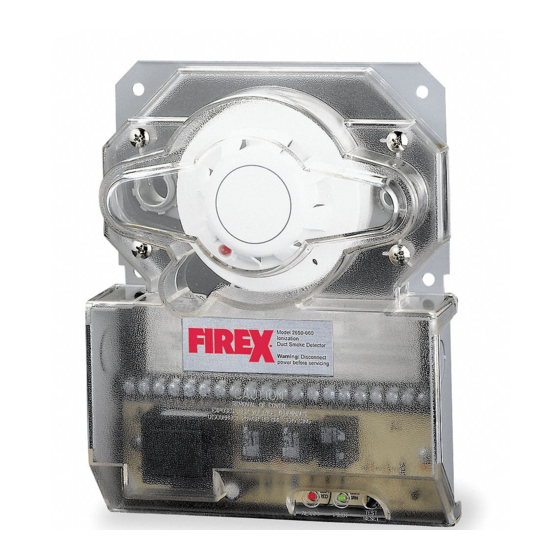
PRODUCT DESCRIPTION:
The Firex Smoke Detector is fitted with a mounting base that will accept an Ionization Detector Head Model # 2850 - 250 or Photoelectric
Detector Head Model # 2850 - 350. The duct unit supports 2 sets of Form "C" Alarm Contacts and 1 form "C" Trouble Contact. The trouble
contact supervises the presence of the input power and removal of the detector head.
THE TROUBLE CONTACTS (TERMINALS 13-14-15) ARE SHOWN IN THE NON-ENERGIZED CONDITION.
The trouble contact will not operate in the event of a smoke alarm.
The Firex Duct Detector models 2650-660 and 2650-661 will operate on one of the following input voltage sources: 24VAC, 24VDC, 115VAC
and 230VAC.
The duct smoke detector units are designed to operate in duct widths from 12 inches to 10 feet wide with an air velocity between 500 and 4000
feet per minute. To verify correct installation, the pressure differential between the input and exhaust tubes should be measured using a
Magnehelic pressure gauge or equivalent. An acceptable reading must be between 0.01 and 1.2 inches of water.
For a Smoke Duct Detector unit to operate correctly, it must be installed 6 duct widths from any obstruction i.e. elbows, deflector plates, filters,
dampers, etc. In situations where the criteria cannot be met, deviations are acceptable providing they meet the pressure differential
requirements.
SAMPLING TUBES:
The principal of operation of a duct detector is based on the Venturi effect. Two tubes extend into the HVAC duct. Air flowing through the duct
is forced into the air intake tube via the air intake holes, and passes over the detector head. The air will be drawn out via the exhaust tube back
into the HVAC duct. (7" exhaust tube provided in the installation kit.)
When the particles of smoke suspended in the air stream reach the alarm threshold of the detector head, the unit will go into alarm.
REMOTE ACCESSORIES:
Audible and visual alarm indicators, remote status indicators and remote reset/test switches can be accommodated by the
Firex Duct units by connecting to the DC voltage output terminals 16 thru 21 (see page 6 for details). These terminals are not supervised and
the current will only be present when the detector unit is in alarm. The remote pilot LED will be permanently illuminated when connected to the
output terminals. Trouble contacts cannot be connected to a fire alarm panel when the trouble (yellow) LED is connected. When connecting the
- trouble LED place a jumper between terminals 14 and 18.
INSTALLATION INSTRUCTIONS FOR
UNIVERSAL DUCT SMOKE DETECTORS
MODEL 2650-660 Ionization
MODEL 2650-661 Photoelectric
PRODUCT OVERVIEW
1
Advertisement
Table of Contents

Subscribe to Our Youtube Channel
Related Manuals for Firex 2650-660


Summary of Contents for Firex 2650-660
-
Page 1: Product Overview
Audible and visual alarm indicators, remote status indicators and remote reset/test switches can be accommodated by the Firex Duct units by connecting to the DC voltage output terminals 16 thru 21 (see page 6 for details). These terminals are not supervised and the current will only be present when the detector unit is in alarm. - Page 2 The pressure differential between the input sampling tube and exhaust tube for the Firex series duct smoke unit should be greater than 0.01 inches of water and less than 1.2 inches of water.
- Page 3 18GA Steel back box, clear plastic cover Finish: Gray paint Dimensions: L-9 1/8” X W-7 1/4” X H-2 1/4” Max. net wt.: 3 1/2 lbs. Radioactive element: For Firex 2650-660 (Ionization model) Americium 241, 0.9 micro curie Do not expose to corrosive atmospheres.
-
Page 4: Test Procedures
MAINTENANCE Each installation location must be assessed on its own merits. If the protected area is of a very dirty nature then the Firex Duct units will have to be checked and cleaned on a Quarterly basis or when cleaning is required. -
Page 5: Electrical Installation
Electrical Installation WIRING Prior to connecting power to the Firex 2650-660 and 2650-661 duct units, determine the correct input voltage and ensure it is connected to the correct terminals. (Refer to power connections) 24V AC/DC,Terminals 5, 6; 115V AC, Terminals 1, 2, 3; 230V AC, Terminals 1, 2, 4... - Page 6 PUSH BUTTON YELLOW CANNOT BE CONNECTED “TEST/RESET “TROUBLE TO FIRE ALARM PANEL SWITCH WHEN USING THIS OPTION JUMPER BLACK TEST / RESET TROUBLE Fire Alarm Control Panel Wiring Listed Fire Alarm Line Control Unit Fig. 1 Firex Detector Firex Detector...
-
Page 7: Common Functions
COMMON FUNCTIONS Unit #1 Unit #2 Unit #3 Unit #1 Unit #2 Unit #3 + RED + RED + RED - BLK - BLK - BLK ALL RELAYS OPERATE WITH SINGLE ALARM ALL RELAYS OPERATE WITH SINGLE ALARM INDIVIDUAL HORN/STROBE OPERATE ON ALARMED DETECTOR ONLY 30 DETECTORS MAX 30 DETECTORS MAX... - Page 8 Maple Chase Company 2820 Thatcher Road Downers Grove, Illinois 60515 USA Telephone +1 630 719 5500 Facsimile +1 630 719 4400 Technical Service Telephone +1 800 445 8299 E-mail mctechservices@maplechase.com www.maplechase.com...
Need help?
Do you have a question about the 2650-660 and is the answer not in the manual?
Questions and answers
where can i get two replacments of firex 2650-560
Two replacements for Firex model 2650-660 can be found on the product page where it is listed for sale at $80.00 each. You can purchase two units by setting the quantity to 2 on that page.
This answer is automatically generated