Table of Contents
Troubleshooting

Subscribe to Our Youtube Channel
Related Manuals for Maretron TLM100


Summary of Contents for Maretron TLM100
- Page 1 TLM100 Tank Level Monitor User’s Manual Revision 1.4 Copyright © 2013 Maretron, LLP All Rights Reserved Maretron, LLP 9014 N. 23 Ave #10 Phoenix, AZ 85021 http://www.maretron.com Maretron Manual Part #: M002201 Revision 1.4 Page i...
-
Page 2: Revision History
TLM100 User’s Manual Revision History Revision Description Original document Corrected typo in NMEA protocol PGN list Typographical corrections Added documentation on mounting locations and theory of operation Corrected torque specifications Added prohibition of red Loctite threadlocking compound and cleaning agents... -
Page 3: Table Of Contents
2.2 Theory of Operation ....................... 3 2.3 Choosing a Mounting Location ..................3 2.3.1 Effect of Pitch and Roll on the TLM100 ............... 4 2.3.2 Use of an Airlock on Black Water Tanks ............. 5 2.3.3 Other Operational Notes ..................5 2.4 Mounting the TLM100 .................... - Page 4 Figure 1 - TLM100 Operation ....................3 Figure 2 – TLM100 Mounting – SAE 5-Hole Bolt Pattern ............7 Figure 3 – Mounting TLM100 to SAE 5-Hole Tank with Focus Tube ......... 8 Figure 4 – TLM100 Mounting With Threaded Adapter ............... 9 Figure 5 –...
-
Page 5: General
TLM100 can be calibrated for irregular tank shapes so you know the true level of your tanks. The TLM100 can be mounted on tanks with a SAE J1810 5-hole mounting pattern, or to tanks using 1.5” NPT or 1.25” BSP threaded openings via available adapters. -
Page 6: Tlm100 Accessories
Custom Calibration (Section 3.4.2) 2 Installation 2.1 Unpacking the Box When unpacking the box containing the Maretron TLM100, you should find the following items: 1 – TLM100 Tank Level Monitor 1 – TLM100 Gasket 1 – Packet of Petroleum Jelly ... -
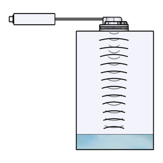
Page 7: Theory Of Operation
The TLM100 operates by directing a pulse of ultrasonic sound from the sensor component at the top of the tank down to the surface of the liquid in the tank. The TLM100 then measures the time it takes this pulse to travel down to the surface of the liquid, be reflected back up, and then be received back at the sensor component. -
Page 8: Effect Of Pitch And Roll On The Tlm100
2.3.1 Effect of Pitch and Roll on the TLM100 Assuming that the TLM100 sensor component is mounted on a flat tank top, the TLM100 will operate correctly as long as the vessel does not experience pitch and/or roll in excess of 6° for an extended period of time. -
Page 9: Use Of An Airlock On Black Water Tanks
This is a tube which mounts into the tank before the sensor and directs the ultrasonic waves down to the surface of the liquid and back. With a focus tube, the TLM100 will operate correctly as long as the vessel does not exceed 15° of pitch and/or roll for extended periods of time. -
Page 10: Mounting The Tlm100 Sensor Component
2.4.2.1 Installation on a Tank with a SAE J1810 5-Bolt Fitting To install the TLM100 on a tank with a SAE J1850 5-bolt fitting, place the gasket over the tank fitting so that the bolt holes line up (WARNING – the gasket must be properly aligned; it only fits one way). -
Page 11: Figure 2 - Tlm100 Mounting - Sae 5-Hole Bolt Pattern
Place the gasket included with the TLM100 over the focus tube so that the bolt holes line up (WARNING – the gasket must be properly aligned; it only fits one way), then place the TLM100 sensor component on top of the TLM100 gasket so that the bolt holes line up. -
Page 12: Figure 3 - Mounting Tlm100 To Sae 5-Hole Tank With Focus Tube
2.4.2.3 Installation on a Tank with a SAE J1810 5-Bolt Fitting and Airlock Installation of the TLM100 on a tank with a SAE J1810 5-bolt fitting with an airlock is identical to installation with a focus tube, except that the trimming step is eliminated. Please refer to Section 0 for details of the mounting procedure. -
Page 13: Figure 4 - Tlm100 Mounting With Threaded Adapter
3-5 ft-lbs (4.1-6.8 N·m). Next, place the TLM100 gasket over the adapter so that the bolt holes on the gasket line up with the bolt holes on the adapter (WARNING – the gasket must be properly aligned; it only fits one way). -
Page 14: Mounting The Tlm100 Interface Component
2.4.2.6 Installation on a Tank with a 1.25”BSP or 1.5”NPT Threaded Tank Fitting and Airlock Installation of the TLM100 on a tank with a 1.25” BSP or 1.5” NPT threaded tank fitting with an airlock is identical to installation with a focus tube, except that the trimming step is eliminated. -
Page 15: Connecting The Tlm100
TLM100 (note the key on the male connector and keyway on the female connector). Be sure the cable is connected securely and that the collar on the cable connector ®... -
Page 16: Configuring The Tlm100
3.3 Configuring Tank Capacity In addition to indicating the fluid level within a tank, the TLM100 also has the ability to be configured or programmed with the attached tank’s capacity. This way, you will be able to view the tank’s capacity as well as the amount of liquid remaining anywhere on the vessel where... -
Page 17: Tank Depth Or Custom Calibration
40” (1.02m), you must program the TLM100 with the actual depth of the tank using a display product such as the Maretron DSM250 or Maretron N2KAnalyzer software. Refer to the user’s manual of the particular product that will be used for configuring the TLM100 as these manuals provide detailed instruction on configuration procedures. -
Page 18: Figure 8 - Troubleshooting Guide
Figure 8 – Troubleshooting Guide If these steps do not solve your problem, please contact Maretron Technical Support (refer to Section 7 for contact information). Page 14... -
Page 19: Technical Specifications
6 Technical Specifications Specifications Parameter Value Comment Accuracy ±2% Resolution ±1% Number of Tank Types Fuel, Fresh Water, Waste Water, Live Well, Oil, etc. Number of Tanks per Tank Type 16 Tanks per Tank Type Numbered 0-15 40” (1.02m) Maximum Tank Depth 2”... -
Page 20: Technical Support
Conducted, Radiated, Supply, and ESD per IEC 60945-10 Safety Precautions Dangerous Voltage, Electromagnetic Radio Frequency per IEC 60945-12 7 Technical Support If you require technical support for Maretron products, you can reach us in any of the following ways: Telephone: 1-866-550-9100... -
Page 21: Maretron (2 Year) Limited Warranty
Maretron (2 Year) Limited Warranty Maretron warrants the TLM100 to be free from defects in materials and workmanship for two (2) years from the date of original purchase. If within the applicable period any such products shall be proved to Maretron’s satisfaction to fail to meet the above limited warranty, such products shall be repaired or replaced at Maretron’s... -
Page 23: Appendix A - Nmea 2000 Interfacing
NMEA command PGN. The TLM100 ships from the factory with a default value of 0xFFFFFFFF indicating “Data Not Available”. 5: Reserved – This field is reserved by NMEA; therefore, the TLM100 sets all bits to a logic 1.
Need help?
Do you have a question about the TLM100 and is the answer not in the manual?
Questions and answers