Table of Contents
Advertisement
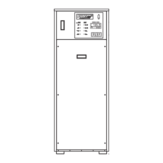
FUTERA II SERIES FINNED COPPER
GAS BOILERS (MODEL FB) &
WATER HEATERS (MODEL FW)
INSTALLATION & OPERATION MANUAL
DESIGNED AND TESTED ACCORDING TO A.S.M.E. BOILER AND PRESSURE
VESSEL CODE, SECTION IV FOR A MAXIMUM ALLOWABLE WORKING PRESSURE
OF 160 PSI, 1103 kPa , WATER.
WARNING: If the information in this manual is not followed exactly, a fire
or explosion may result causing property damage, personal injury or loss of life.
Do not store or use gasoline or other flammable vapors and liquids in the vicinity of
this or any other appliance.
WHAT TO DO IF YOU SMELL GAS:
• Do not try to light any appliance.
• Do not touch any electrical switch. Do not use any phone in your building.
• Immediately call your gas supplier from a neighbor's phone. Follow the gas
supplier's instructions.
• If you cannot reach your gas supplier, call the fire department.
Installation and service must be performed by a qualified installer, service agency or
the gas supplier.
WARNING: Failure to properly vent this unit can cause excessive amounts of carbon
monoxide resulting in severe personal injury or death!
INSTALLER, THESE INSTRUCTIONS TO BE AFFIXED ADJACENT TO THE BOILER / WATER HEATER.
CONSUMER, RETAIN THESE INSTRUCTIONS FOR FUTURE REFERENCE PURPOSES.
260 North Elm Street
1300 Midway Boulevard
Westfield, MA 01085
Mississauga, Ontario L5T 2G8 Canada
Phone: (413) 568-9571
Phone: (905) 670-5888
Fax: (413) 568-9613
Fax: (905) 670-5782
www.rbiwaterheaters.com
FTII-IOM-5
Advertisement
Table of Contents

Related Manuals for RBI FB series


Summary of Contents for RBI FB series
- Page 1 FTII-IOM-5 FUTERA II SERIES FINNED COPPER GAS BOILERS (MODEL FB) & WATER HEATERS (MODEL FW) INSTALLATION & OPERATION MANUAL DESIGNED AND TESTED ACCORDING TO A.S.M.E. BOILER AND PRESSURE VESSEL CODE, SECTION IV FOR A MAXIMUM ALLOWABLE WORKING PRESSURE OF 160 PSI, 1103 kPa , WATER. WARNING: If the information in this manual is not followed exactly, a fire or explosion may result causing property damage, personal injury or loss of life.
-
Page 2: Table Of Contents
Diagnostics ............page 30 MUST FOLLOW the additional instructions contained in Maintenance ............page 31 RBI’s instruction sheet MACODE-1. If you do not have a copy, call your RBI distributor or contact the RBI Customer Trouble-Shooting ..........page 33 Service Department. -
Page 3: Ratings & Capacities
FUTERA II INSTALLATION AND OPERATION INSTRUCTIONS RATINGS & CAPACITIES NEVER place this boiler/water heater in a location that Before undertaking the installation of the Futera II Series would subject it to temperatures at or near freezing. boiler/water heater check the rating plate to ensure that the See the “Freeze Protection”... - Page 4 3 in, 76 mm from, the top of the enclosure. using the direct vent option. The RBI air intake adapter The bottom opening must be within 12 in, 305 mm of, but must be fitted to the blower inlet.
-
Page 5: Vent System Options
3.1 m of pipe. If horizontal runs exceed 5 ft, 1.5 m they must be supported at 3 ft, 0.9 m intervals with overhead hangers. The certified combustion air terminal from RBI must be used and installed as shown in Figures 3 and 4. - Page 6 Protect building ULS636 for installations in Canada. The certified vent materials and vegetation from degradation caused by the terminal from RBI must also be used. flue gases. The maximum equivalent length for the horizontal vent Vertical Direct Vent Systems –...
- Page 7 FUTERA II INSTALLATION AND OPERATION INSTRUCTIONS Figure 1 - Air Intake Vertical or Thru Wall Figure 2 - Venting Thru Wall/Vertical...
- Page 8 FUTERA II INSTALLATION AND OPERATION INSTRUCTIONS Figure 3 – Horizontal Air Intake and Venting for a Single Direct Vent System 4 FT 1.2 m 1/4 IN. PER FOOT 20 mm/m 3 FT 0.9 m 16 FT 4.9 m 5 FT 1.5 m 5 FT 1.5 m 1.5 FT 0.5 m When running horizontal combustion air and venting for single or multiple units, exhaust and combustion air terminals...
- Page 9 FUTERA II INSTALLATION AND OPERATION INSTRUCTIONS Figure 5 - Vertical Air Intake and Venting for Direct Vent System Figure 6 – Combination Direct Vent Systems...
- Page 10 FUTERA II INSTALLATION AND OPERATION INSTRUCTIONS SIDE WALL VENT, VERTICAL/CHIMNEY VENT, POSITIVE PRESSURE, CATEGORY III NEGATIVE PRESSURE, CATEGORY I In this configuration the boiler/water heater blower is used The Futera II is listed as a Category I appliance when to push the flue products horizontally to the outdoors, see vented vertically into a listed metal chimney system or Figure 7.
- Page 11 FUTERA II INSTALLATION AND OPERATION INSTRUCTIONS The vent connector should be sloped up toward the WARNING: Failure to maintain minimum chimney at a minimum rate of 1/4 in/ft, 21 mm/m . On clearances between vent connectors and any masonry chimneys the connector must terminate flush with combustible material can result in a fire causing the inside of the chimney flue, Figure 9.
- Page 12 FUTERA II INSTALLATION AND OPERATION INSTRUCTIONS Figure 8 – Vertical Venting with a Metal Chimney System...
-
Page 13: Outdoor Venting
FUTERA II INSTALLATION AND OPERATION INSTRUCTIONS Figure 9 – Vertical Venting using a Masonry Chimney 24" .6 m OUTDOOR VENTING When installed outdoors the Futera II must be fitted with CAUTION: Do not place the boiler/water heater in a location that would subject it to runoff from adjacent the factory supplied outdoor hood, air intake adapter with buildings or damage may occur voiding the warranty! filter and exhaust terminal, see Figure 10. -
Page 14: Common Vent Systems
FUTERA II INSTALLATION AND OPERATION INSTRUCTIONS COMMON VENT SYSTEMS e) Test for spillage at the draft hood relief opening after 5 If an existing boiler/water heater is removed from a minutes of main burner operation. Use the flame of a common venting system, the common venting system may match or candle, or smoke from a cigarette, cigar or then be too large for the proper venting of the remaining... - Page 15 FUTERA II INSTALLATION AND OPERATION INSTRUCTIONS NOTE: Shut off valves and unions should be installed CAUTION: Improper outdoor installation of this unit at the inlet and outlet connections of the boiler/hot can cause boiler failure voiding the manufacturer’s water heater to provide for isolation of the unit should warranty! servicing be necessary.
-
Page 16: Heating System Piping
FUTERA II INSTALLATION AND OPERATION INSTRUCTIONS HEATING SYSTEM PIPING Table 5 - Temperature Rise Table ∆T = 20°F ∆ T = 11.1 ° C Model Flow Rate Pres. Drop Flow Rate Pres. Drop General Piping Requirements Number All heating system piping must be installed by a qualified 42.5 0.53 technician in accordance with the latest revision of the... - Page 17 FUTERA II INSTALLATION AND OPERATION INSTRUCTIONS Low Water Cutoff Low Return Water Temperatures If a boiler is installed above any radiation elements it must To prevent the problems associated with condensation of be fitted with a low water cutoff device. the products of combustion due to low return water temperatures a primary/secondary piping system with a Refer to the wiring diagram supplied with the boiler/water...
- Page 18 FUTERA II INSTALLATION AND OPERATION INSTRUCTIONS Figure 13 - Typical Boiler Primary/Secondary Piping System (See Notes) Pump Gate Valve Globe Valve Angle Valve Bufferfly Valve Balance Valve Ball Valve Motorized Valve Solenoid Operated Valve H-1 Rev 2 Self-Operated Valve Figure 14 - Low Temperature Boiler Piping (See Notes and Adjustment Procedures) Pressure Reducing Valve...
- Page 19 FUTERA II INSTALLATION AND OPERATION INSTRUCTIONS Figure 15 - Multiple Boiler Piping (See Notes) Pump Gate Valve Globe Valve Angle Valve Bufferfly Valve Balance Valve Ball Valve Motorized Valve Solenoid Operated Valve Self-Operated Valve Pressure Reducing Valve Check Valve Pressure Relief Valve H-15 Rev 2 Flow Switch...
-
Page 20: Domestic Water Supply Piping
General Piping Requirements Ensure that the water heater is equipped with bronze RBI water heaters are designed to run scale free. Due to headers. Piping and components connected to the water the extreme variables of water conditions world wide it is heater must be suitable for use with potable water. - Page 21 FUTERA II INSTALLATION AND OPERATION INSTRUCTIONS Table 5A - Futera II Heat Exchanger Selection Graph Table 5B - Futera II Pumping Performance Requirement...
- Page 22 FUTERA II INSTALLATION AND OPERATION INSTRUCTIONS Expansion Tank A balancing valve should be installed on the outlet side of An expansion tank or other means to control thermal the water heater for purposes of adjusting the flow rate expansion must be installed in the water heating system if through the heat exchanger.
- Page 23 FUTERA II INSTALLATION AND OPERATION INSTRUCTIONS Figure 16 - Typical Water Heating Piping (FW Models Only) (See Notes) Pump Valve Globe Valve Angle Valve D-1 Rev. 4 Bufferfly Valve Balance Valve Ball Valve Motorized Valve Figure 17 - Multiple Water Heating Piping (FW Models Only) (See Notes) Solenoid Operated Valve...
-
Page 24: Gas Supply Piping
If for any reason the boiler/water heater is not for the type of gas available at the installation site, call your RBI representative to resolve the problem. NOTE: A minimum gas supply pressure of 6 in, 152 mm W.C. -
Page 25: Electrical Wiring
FUTERA II INSTALLATION AND OPERATION INSTRUCTIONS ELECTRICAL WIRING Hydronic Heating Boilers Open the make-up water valve and slowly fill the boiler and Electrical Power Connections all of the radiation with water. Ensure that all bleed and drain valves are closed. CAUTION: Label all wires prior to disconnection when servicing controls. - Page 26 FUTERA II INSTALLATION AND OPERATION INSTRUCTIONS DANGER: Propane gas may not always be detected Wait five (5) minutes to clear out any gas. Then smell by smell. Propane gas is heavier than air and can for gas, including near the floor. If you smell gas, collect in low areas.
-
Page 27: Checking & Adjustments
FUTERA II INSTALLATION AND OPERATION INSTRUCTIONS CHECKING & ADJUSTMENTS Pilot Operation On initial light-off, the installer may alter the preset factory With the manual main gas valve and manual pilot gas valve settings to attain satisfactory combustion. An accurate closed energize the unit and allow it to try for ignition until manometer and flue gas analyzer must be used. - Page 28 FUTERA II INSTALLATION AND OPERATION INSTRUCTIONS When fire tested at the factory the unit’s input was Figure 21 – Air Box Pressure Tap rated and the gas pressure(s) recorded on the test label affixed to the jacket next to the junction box. To confirm the input of the unit follow the instructions in the INPUT RATE section below.
-
Page 29: Control Description
FUTERA II INSTALLATION AND OPERATION INSTRUCTIONS “Static and operating gas pressure required at the gas Check the input rate as follows: valve inlet is between 6" W.C. and 14" W.C. for natural gas Turn off all other gas appliances that use the same gas and 11"... -
Page 30: Diagnostics
Call For Low Fire: This green light will illuminate when there SP Setpoint or Target Temperature: is a low fire heat demand either from the RBI Temperature The Setpoint is the inlet water temperature that the Controller or a Building Management Control. -
Page 31: Maintenance
FUTERA II INSTALLATION AND OPERATION INSTRUCTIONS MAINTENANCE If there are no signs of damage, sooting or corrosion, reassemble the unit following the previous steps in WARNING: Disconnect electrical power and close reverse order. the manual gas shut off valve before performing A badly corroded or damaged heat exchanger must be replaced, see the Heat Exchanger Repair &... - Page 32 FUTERA II INSTALLATION AND OPERATION INSTRUCTIONS Controls Use the “GENERAL OPERATION” and “CHECKING AND WARNING: A yellow, floating flame indicate a lack ADJUSTMENTS” sections of this manual for reference. of combustion air. Do not operate the boiler/water Check the thermostat or operating controls for proper heater until the problem is solved or severe operation.
-
Page 33: Trouble-Shooting
FUTERA II INSTALLATION AND OPERATION INSTRUCTIONS TROUBLE-SHOOTING OPERATIONAL PROBLEMS CORRECTIVE ACTION The On/Off toggle switch light doesn’t illuminate. Ensure that proper voltage is being supplied to the unit. Inspect the circuit breaker for the boiler/water heater circuit. Ensure that the power switch operates properly and is wired correctly. -
Page 34: Repair Parts
FUTERA II INSTALLATION AND OPERATION INSTRUCTIONS Figure 24 – Exploded View... - Page 35 FUTERA II INSTALLATION AND OPERATION INSTRUCTIONS Futera II Model Size with Item Quantities Below Ref # Name of Part Part # 1000 1250 1500 1750 1950 Base Panel Assembly 70-2163 70-2164 Gas Train Support Bracket 03-1639 Base Panel Heat Exchanger Legs 03-1599 03-1600 Combustion Chamber Top Panel...
- Page 36 FUTERA II INSTALLATION AND OPERATION INSTRUCTIONS Futera II Model Size with Item Quantities Below Ref # Name of Part Part # 1000 1250 1500 1750 1950 Drain Valve 11-0396 Drain Valve Assembly (FB) 30-0427K 30-0428K Drain Valve Assembly (FW) 30-0436K 30-0437K Drain Valve Assembly (FB) (Outdoor) 30-0420K...
- Page 37 FUTERA II INSTALLATION AND OPERATION INSTRUCTIONS Futera II Model Size with Item Quantities Below Ref # Name of Part Part # 1000 1250 1500 1750 1950 Jacket Left Side Panel 03-1767 03-1768 03-1769 03-1770 03-1771 03-1772 03-1773 Jacket Right Side Panel 03-1774 03-1775 03-1776...
- Page 38 FUTERA II INSTALLATION AND OPERATION INSTRUCTIONS Futera II Model Size with Item Quantities Below Ref # Name of Part Part # 1000 1250 1500 1750 1950 Main Gas Valve, V4944B, 1", 120V 11-0166 Main Gas Valve, V4944B, 1 1/4", 120V 11-0167 Main Gas Valve, V4944B, 1 1/2", 120V 11-0168...
- Page 39 FUTERA II INSTALLATION AND OPERATION INSTRUCTIONS Futera II Model Size with Item Quantities Below Ref # Name of Part Part # 1000 1250 1500 1750 1950 Heat Exchanger Assembly (Copper) 70-2186 70-2187 70-2188 70-2189 70-2190 70-2191 70-2192 Heat Exchanger Assembly (Cupronickel) 70-2193 70-2194 70-2195...
- Page 40 FUTERA II INSTALLATION AND OPERATION INSTRUCTIONS Futera II Model Size with Item Quantities Below Ref # Name of Part Part # 1000 1250 1500 1750 1950 OPTIONS Alarm Contact 30-0781 Alarm Bell 70-2232 Flame Failure Dry Contact 30-0757 Enable/Disable Relay 24V 30-0824 Main Flame Status Contact 30-0759...
-
Page 41: Start Up Sheet
FUTERA II START UP SHEET Date of Start Up: RBI Ref. #: Serial # ('s): Boiler #1 Model# Boiler #2 Boiler #3 Boiler #4 Boiler #5 The above information will be used to identify each boiler in the system. You should make every attempt to affix the boiler number as noted here to the boiler physically. - Page 42 SAFETY CHECKS AND ADJUSTMENTS Readings Or Checks By Boiler Number STEP DESCRIPTION Low water cut off Low gas pressure High gas pressure Operator okay and set @: High limit okay and set @: Blocked flue switch drops out at ("W.C".): Flame fail time: With fan running: Record air box pressure "W.C".
- Page 43 FUTERA II START UP CHECK LIST The following items must be field verified as complete prior to the scheduling of factory authorized start up. 1. All electrical is installed and checked: ............2. All water connections are made: ..............3. System is flooded and pressure tested: ............4.
- Page 44 260 North Elm Street 1300 Midway Boulevard Westfield, MA 01085 Mississauga, Ontario L5T 2G8 Canada Phone: (413) 568-9571 Phone: (905) 670-5888 Fax: (413) 568-9613 Fax: (905) 670-5782 www.rbiwaterheaters.com...
Need help?
Do you have a question about the FB series and is the answer not in the manual?
Questions and answers