Table of Contents
Advertisement
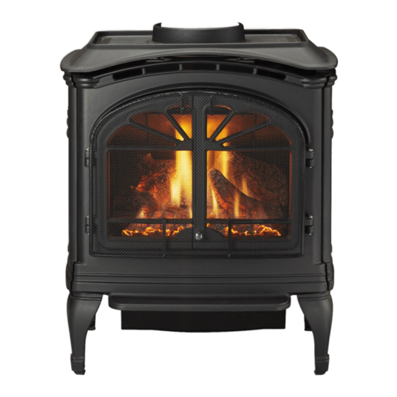
TIARA I-B
TIARA II-B
DIRECT VENT ROOM HEATER
Models:
TIARAI-BK-B
TIARAI-BR-B
TIARAI-CTO
TIARAI-CES
• Important operating and
maintenance instructions
included.
WARNING: If the information in these
instructions is not followed exactly, a fi re
or explosion may result causing property
damage, personal injury, or death.
• Do not store or use gasoline or other fl am-
mable vapors and liquids in the vicinity of this
or any other appliance.
• What to do if you smell gas
- Do not try to light any appliance.
Do not touch any electrical switch. Do not
use any phone in your building.
- Immediately call your gas supplier from a
neighbor's phone. Follow the gas supplier's
instructions.
- If you cannot reach your gas supplier, call
the fi re department.
• Installation and service must be performed
by a qualifi ed installer, service agency, or the
gas supplier.
Installation and service of this appliance should be
performed by qualifi ed personnel. Hearth & Home
Technologies suggests NFI certifi ed or factory-trained
professionals, or technicians supervised by an NFI
certifi ed professional.
TIARAII-BK-B
TIARAII-BR-B
TIARAII-CTO
TIARAII-CES
DO NOT DISCARD THIS MANUAL
• Read, understand and
follow these instructions
for safe installation and
operation.
CAUTION
• Leave this manual with
party responsible for use
and operation.
Hot glass will cause burns.
• Do not touch glass until it is cooled
• NEVER allow children to touch glass
• Keep children away
• CAREFULLY SUPERVISE children in the same room
as appliance
• Alert children and adults to hazards of high
temperatures
High temperatures may ignite clothing or other
fl ammable materials.
• Keep clothing, furniture, draperies and other
combustibles away.
In the Commonwealth of Massachusetts:
• installation must be performed by a licensed plumber or gas
fi tter.
See Table of Contents for additional Commonwealth of Mas-
sachusetts requirements.
This appliance may be installed as an OEM installation in manufactured
home (USA only) or mobile home and must be installed in accordance with
the manufacturer's instructions and the manufactured home construction and
safety standard, Title 24 CFR, Part 3280 or Standard for Installation in Mobile
Homes, CAN/CSA Z240MH.
This appliance is only for use with the type(s) of gas indicated on the rating plate.
7010-149M
Owner's Manual
Installation and Operation
O-T L
O-T
Tested and
Listed by
C
OMNI-Test Laboratories, Inc.
WARNING
HOT SURFACES!
Glass and other surfaces are
hot during operation AND
cool down.
August 1, 2008
Portland
Oregon USA
US
Advertisement
Table of Contents

Related Manuals for Heat & Glo TIARA I-B

Summary of Contents for Heat & Glo TIARA I-B
-
Page 1: Installation And Operation
TIARA I-B TIARA II-B DIRECT VENT ROOM HEATER Models: TIARAI-BK-B TIARAII-BK-B TIARAI-BR-B TIARAII-BR-B TIARAI-CTO TIARAII-CTO TIARAI-CES TIARAII-CES • Important operating and maintenance instructions included. WARNING: If the information in these instructions is not followed exactly, a fi re or explosion may result causing property damage, personal injury, or death. - Page 2 Read this manual before installing or operating this appliance. Please retain this owner's manual for future reference. Congratulations on selecting a Heat & Glo gas appliance - an elegant and clean alternative to wood burning appliances. The Heat & Glo gas appliance you have selected is designed to provide the utmost in safety, reliability, and efficiency.
-
Page 3: Table Of Contents
C. Damper Adjustment ...31 D. Shutter Adjustment ...32 E. Leg Leveling System ...32 F. Installing the Baffl e - Tiara I-B ...32 G. Brick Installation - Tiara II-B ...32 H. Positioning the Logs - Tiara I-B ...33 J. Mineral Wool ...34 K. -
Page 4: Section 1: Listing And Code Approvals
Listing and Code Approvals A. Appliance Certifi cation MODEL Tiara I B LABORATORY OMNI-Test Laboratories, Inc. 061-S-43b-5 TYPE Vented Gas Fireplace Heater STANDARD ANSI Z21.88-2002 ּ UL307b CAN/CBA 2.17-M91 MODEL Tiara II B LABORATORY OMNI-Test Laboratories, Inc. 061-S-44b-5 TYPE Vented Gas Fireplace Heater STANDARD ANSI Z21.88-2002 ּ... -
Page 5: Requirements For The Commonwealth Of Massachusetts
NOTE: The following requirements reference various Massachusetts and national codes not contained in this document. G. Requirements for the Commonwealth of Massachusetts For all side wall horizontally vented gas fueled equipment installed in every dwelling, building or structure used in whole or in part for residential purposes, including those owned or operated by the Commonwealth and where the side wall exhaust vent termination is less than seven (7) feet above... -
Page 6: Section 2: Getting Started
Getting Started A. Design & Installation Considerations Heat & Glo direct vent gas appliances are designed to oper- ate with all combustion air drawn from outside of the building and all exhaust gases expelled to the outside. No additional air source is required. CAUTION Check building codes prior to installation. -
Page 7: Section 3: Appliance Location & Clearances A. Selecting Appliance Location
When selecting a location for your appliance it is important to consider the required clearances to wall (see Figure 3.1). NOTE: For actual appliance dimensions refer to Section 12. B. Clearances to Combustibles - Tiara I-B "A" measurement is from appliance top, not side Model... -
Page 8: Clearances To Combustibles - Tiara Ii-B
Tiara II B Inches 5-1/4 Millimeters Figure 3.1 For both the Tiara I-B and Tiara II-B, it is permissible to place the appliance on carpet. CAUTION Some carpet materials may be sensitive to radiant heat from the appliance causing discoloration or odor. -
Page 9: Vent Termination Minimum Clearances
Termination Locations A. Vent Termination Minimum Clearances WARNING Fire Risk. Explosion Risk. Maintain vent clearance to combustibles as specifi ed. • Do not pack air space with insulation or other materials. Failure to keep insulation or other materials away from vent pipe may cause fi re. Measure vertical clearances from this surface. - Page 10 = VENT TERMINAL = 12 inche s ... clearances above grade , veran- (S ee N ot e 1 ) da, porch, deck or balcon y = 12 inche s ... clearances to window or doo r that may be opened, or to per - manen t ly closed windo w .
-
Page 11: Section 5: Vent Information
Vent Information A. Venting Components In order to comply with applicable codes and product warranties, use only following venting components: • Hearth & Home Technologies (HHT) • Simpson Dura-Vent • Selkirk Direct-Temp • Amerivent Direct • Security Secure Vent FIELD-FABRICATED COMPONENTS. -
Page 12: How To Use The Vent Graph
• For any vertical termination a minimum of 6 ft. (2m) vertical must be used. EXCEPTIONS FOR HORIZONTAL INSTALLATIONS: *When installing the Tiara I-B or Tiara II-B in a rear vent configuration with no vertical rise, a Snorkel Kit must be used. Refer to venting components. -
Page 13: Horizontal Termination
F. Horizontal Termination Type A - Up & Out Installation 90° ELBOW CENTER LINE PIPE LENGTH WALL THIMBLE/ HEAT SHIELD WALL THIMBLE COVER PIPE LENGTH Type B - Straight Out Installation 15-5/8 in. (397mm) WALL THIMBLE COVER CENTER LINE PIPE LENGTH WALL STRAP 14 in. - Page 14 Step 3. For installations using a round support box/wall thimble (check pipe manufacturer's instructions), mark the wall for a 10 in. x 10 in. (254mm x 254mm) square hole. The center of the square hole should line up with the center line of the horizontal pipe, as shown in Figure 5.5.
- Page 15 VINYL SIDING Apply sealant to all four sides WALL THIMBLE COVER Vinyl siding standoff with siding beneath removed WALL THIMBLE Figure 5.8 Step 5. Place the wall thimble cover over the pipe assembly and slide the appliance and vent assembly towards the wall, carefully inserting the vent pipe into the vent termination cap assembly.
-
Page 16: Vertical Termination
G. Vertical Termination 1. Direct Vent Pipe STORM COLLAR FIRESTOP PIPE LENGTH Figure 5.10 Step 1. Check the installation instructions for required 1 in. (25mm) clearances (air space) to combustibles when passing through ceilings, walls, roofs, enclosures, attic rafters, or other nearby combustible surfaces. - Page 17 Step 3. To install the round support box/wall thimble cover in a flat ceiling, cut a 10 in. (254mm) square hole in the ceiling, centered on the hole drilled in Step 2. Frame the hole as shown in Figure 5.13. Framing Figure 5.13 Step 4.
- Page 18 Step 9. Twist-lock the vent cap and seal. Note: For multi-story vertical installations, a ceiling firestop is required at the second floor, and any subsequent floors (Figure 5.16). The opening should be framed to 10 in. x 10 in. (254mm x 254mm) inside dimensions, in the same manner as shown in Figure 5.13, on the previous page.
- Page 19 2. Cathedral Ceiling Step 1. Follow installation Steps 1 and 2 under vertical installation section, page 16. Step 2. Remove shingles or other roof covering as necessary to cut the rectangular hole for the support box. Cut the hole 1/8 in. (3mm) larger than the support box outline.
- Page 20 3. Class A Metal Chimney EXISTING METAL CHIMNEY SYSTEM DIRECT VENT PIPE Figure 5.20 CAUTION Ensure that existing chimney is functionally sound and clean. • Have inspection done by qualified chimney sweep or professional installer BEFORE converting to direct vent appliance.
-
Page 21: Existing Masonry Chimney
4. Existing Masonry Chimney Co-Axial to Co-Linear Connector Pipe Length Optional Type C - Up & Out Installation TOP ADAPTOR RETRO CONNECTOR 90° ELBOW DIRECT VENT PIPE Figure 5.24 August 1, 2008 Type A & B Co-Axial to Co-Linear Chimney Liner Termination Cap 3 in. - Page 22 CAUTION Ensure that existing chimney is functionally sound and clean. • Have inspection done by qualified chimney sweep or professional installer BEFORE converting to direct vent appliance. Step 1. Before cutting any holes, assemble the desired sections of direct vent pipe to determine the center of the masonry penetration.
- Page 23 Figure 5.27 Step 8. Secure the top adapter to the flashing. Use three sheet metal screws through the side of the top adapter into the flange on the flashing (Figure 5.28). Twist lock the high wind termination cap on to the top adapter. High Wind Termination Cap Top Adaptor...
-
Page 24: Section 6: Gas Information
Torx TH20, 5/32 in. Allen wrench, 5/8 in. open end wrench, Remove front (if installed), glass, and logs (if installed.) Tiara I-B Burner Removal: Figure 6.1 Remove the optional brick set, if installed. Remove the two screws, one on each side of burner. Retain fasteners for reinstallation. -
Page 25: Valve Regulator Replacement
.073 Reinstall burner by placing it into the fi rebox. August 1, 2008 Tiara I-B: Installation is the reverse of the removal. DO NOT OVERTIGHTEN. Reinstall the optional brick set, if applica- ble. Tiara II-B: Installation is the reverse of the removal. Make THERMOCOUPLE sure to reinstall the two 1/4 in. -
Page 26: Gas Pressures
Identification Label Ensure that the rubber gasket (4) is properly posi- Figure 6.7 tioned and install the new HI/LO pressure regulator assem- bly to the valve using the new screws (5) supplied with the kit. Tighten screws securely. (Reference torque = 25 in./lb.) Install the enclosed identifi... -
Page 27: Gas Connection
C. Gas Connection NOTE: Have the gas supply line installed in accordance with local building codes, if any. If not, follow ANSI Z223.1. Instal- lation should be done by a qualifi ed installer approved and/or licensed as required by the locality. (In the Commonwealth of Massachusetts, installation must be performed by a licensed plumber or gas fi... -
Page 28: Section 7: Electrical Information
Electrical Information A. Recommendation for Wire See B5 below for recommended maximum lead length (two wire) when using wall thermostat/switch. NOTE: This appliance must be electrically wired and grounded in accordance with local codes or, in the absence of local codes, with National Electric Code ANSI/NFPA 70-latest edition or the Canadian Electric Code, CSA C221.1. -
Page 29: Ignition Module Access And Battery Replacement
The Ignition Module (automatic-ignitor) is located on the side of the appliance. This module was incorporated into the design of the Tiara I-B & II-B to facilitate "one hand" lighting of the appliance. When the gas control knob is turned to the "Pilot"... -
Page 30: Section 8: Appliance Setup
Appliance Setup A. Remove Shipping Materials Remove shipping materials from inside or underneath the fi rebox. B. Top to Rear Vent Conversion TOOLS REQUIRED: Power drill; #2 Phillips bit; high-temp sealant (optional). Figure 8.1 Remove top grille, as highlighted. CAUTION Sharp Edges •... -
Page 31: Damper Adjustment
Figure 8.6 Place cover plate and gasket over top vent and attach with the eight screws removed in Figure 8.2. Figure 8.7 Insert inner collar adapter to rear fl ue vent. Figure 8.8 Install vent pipe adapter with gasket or high-temp sealant to rear vent opening. -
Page 32: Shutter Adjustment
CLOSE Figure 8.14 up and down to desired level. F. Installing the Baffl e - Tiara I-B Figure 8.15 and right sides. Centering baffl e on retainers, ensure that the dark painted bevelled edge and darker painted baffl e bottom side faces toward the front viewing area of the fi... -
Page 33: Positioning The Logs - Tiara I-B
TABS easily. PLEASE NOTE: Logs have been designed to work specifically with the burners of the Tiara I-B and Tiara II- B. Exact placement will ensure proper operation of your gas appliance and reduce sooting. Figure 8.20 Figure 8.21... -
Page 34: Positioning The Logs - Tiara Ii-B
I. Positioning the Logs - Tiara II-B Figure 8.23 Place rear log onto the two locating pins located on the rear log shelf in the back of the fi rebox. Figure 8.24 Place left and right logs into recesses cut out for them on the left and right side of the burner. -
Page 35: Optional Blower
M. Optional Blower KIT CONTENTS: Blower; speed control; lock nut; control knob; ground clip; temperature sensor switch; wing nut; 2 high-temp black wires; 1 high-temp blue wire. TOOLS REQUIRED: Philips head screwdriver; 1/2 in. wrench. The GFK-160A blower has been designed to circulate room air through the appliance to enhance heat output. - Page 36 SPEED CONTROL Figure 8.31 Remove the knob and lock nut from the speed control. Install speed control onto access panel with stem sticking out the pre-punched hole. Attach the lock nut tightly and reattach the knob on the stem. Attach blue and black wires routed through orange grommet in fan housing to the speed control.
-
Page 37: Warming Shelves Installation
Remove the front by lifting upwards 1/2 in. (13mm) and away from the appliance. Tiara I-B: Remove the glass door by opening the latches located on both the left and right sides at the bottom of the glass. Pull towards you and separate latches from notches. -
Page 38: Section 9: Operating Instructions
Operating Instructions A. Before Lighting Appliance Read this entire manual prior to using the appliance. Failure to follow the instructions may result in property damage, bodily injury, or even death. • Remove all shipping materials from inside and/or underneath the fi rebox. •... -
Page 39: Lighting Appliance
C. Lighting Appliance FOR YOUR SAFETY READ BEFORE LIGHTING FOR YOUR SAFETY READ BEFORE LIGHTING WARNING: If you do not follow these instructions exactly, a fire or explosion may result causing property damage, personal injury or loss of life A. This appliance has a pilot that must be lit manually. When lighting the pilot, follow these instructions exactly. B. -
Page 40: After Appliance Is Lit
D. After Appliance is Lit Initial Break-in Procedure When you light your appliance, you may notice that it pro- duces heat which does have an associated odor or smell. If you feel this odor is excessive it may require the initial three to four hour continuous burn on high followed by a second burn up to 12 hours to fully drive off any odor from paint and lubricants used in the manufacturing process. -
Page 41: Section 10: Troubleshooting
Troubleshooting With proper installation, operation, and maintenance your gas appliance will provide years of trouble-free service. If you do experience a problem, this troubleshooting guide will assist a qualifi ed service person in the diagnosis of a problem and the corrective action to be taken. - Page 42 Symptom Possible Cause 3. (Continued) c. Defective valve. d. Plugged burner orifi ce. e. Wall switch or wires are defective. 4. Frequent pilot outage a. Pilot fl ame may problem. be too high or too low, or blowing (high), causing safety pilot to drop out.
-
Page 43: Maintaining And Servicing Appliance
Maintaining and Servicing Appliance Although the frequency of your appliance servicing and maintenance will depend on use and the type of installation, a qualifi ed service technician should perform an appliance check-up at the beginning of each heating season. WARNING Risk of injury or property damage. -
Page 44: Maintenance Tasks
A. Maintenance Tasks Inspect Doors 1. Inspect for scratches, dents or other damage and repair as necessary. 2. Verify no obstructions to air fl ow. 3. Verify maintenance of proper clearance to combustible household objects. Gasket Seal, Glass 1. Inspect gasket seal and its condition. Assembly and Glass 2. -
Page 45: Section 12: Reference Materials
Reference Materials A. Appliance Dimension Diagram - Tiara I-B Dimensions are actual appliance dimensions. Use for reference only. For clearances to combustibles refer to Section 3. NOTE: Diagrams show gas appliance equipped with optional Blower, Part #GFK-160A. Location Figure 12.1... -
Page 46: Appliance Dimension Diagram - Tiara Ii-B
B. Appliance Dimension Diagram - Tiara II-B Dimensions are actual appliance dimensions. Use for reference only. For clearances to combustibles refer to Section 3. NOTE: Diagrams show gas appliance equipped with optional Blower, Part #GFK-160A. Location Figure 12.2 Appliance Dimensions Page 46 Inches Millimeter... -
Page 47: Vent Components Diagram
C. Vent Components Diagram 6-3/8 in. (162mm) 6-1/2 in. (165mm) 9-1/4 in. (235mm) 6-1/2 in. (165mm) 9-5/8 in. 6-3/8 in. (244mm) (162mm) 6-5/8 in. (168mm) SLP45-BK 6-5/8 in. (168mm) 9-5/8 in. SLP90M (244mm) 17-24 in. 6-1/2 in. (432-610mm) (165mm) 11-3/4 in. (298mm) 5-3/4 in. -
Page 48: Vent Components List
D. Vent Components List Description 4” Pipe Length, Galvanized 4” Pipe Length, Black 6” Pipe Length, Galvanized 6” Pipe Length, Black 7” Pipe Length, Galvanized 7” Pipe Length, Black 9” Pipe Length, Galvanized 9” Pipe Length, Black 12” Pipe Length, Galvanized 12”... - Page 49 Description 45° Elbow, Swivel, Black 90° Elbow, Galvanized 90° Elbow, Black 90° Elbow, Swivel, Galvanized 90° Elbow, Swivel, Black Adjustable Flashing, 0/12-6/12 Adjustable Flashing, 7/12-12/12 Attic Insulation Shield - Cold Climates 36” Attic Insulation Shield 12” Attic Insulation Shield, Adjustable 11”-20” Cathedral Support Box Ceiling Support Co-Axial to Co-Lineal Appliance Connector...
-
Page 50: Service Parts List - Tiara I-B
Valve Access Assembly Valve, Replacement Switch, Rocker, ON/OFF Back Shield Ignition Module Heat & Glo · Tiara I B & Tiara II B · 7010-149M TIARA I-B Beginning Manufacturing Date: 8-03 Ending Manufacturing Date: Item Description Grille, Top Vent Baffl e Bracket Baffl... - Page 51 August 1, 2008 Service Parts List (NG, LP) Exploded Parts Diagram Part Description Alphabetical Order Heat & Glo · Tiara I B & Tiara II B · 7010-149M TIARA I-B (cont’d.) Beginning Manufacturing Date:8-03 Ending Manufacturing Date: 200-2470 7000-162 7002-016...
- Page 52 Page 52 Service Parts List (NG, LP) Exploded Parts Diagram Part Description Alphabetical Order Heat & Glo · Tiara I B & Tiara II B · 7010-149M TIARA I-B (cont’d.) Beginning Manufacturing Date:8-03 Ending Manufacturing Date: Part # 7010-116 844-5750...
-
Page 53: Accessories - Tiara I-B
Item Wire Harness Door, Left Door, Right Front Side Warming Shelf Support Accessories - Tiara I-B Item Brick Set Fan Kit, 160 CFM Log Set Mesh Screen Rear Vent Grille Remote Control 110 VAC... -
Page 54: Service Parts List - Tiara Ii-B
Item Description Brick Assembly Log Set Bulkhead Stop Bulkhead Air Shutter Assembly Front Door Assembly Burner Assembly Page 54 Service Parts List (NG, LP) Exploded Parts Diagram Item Description Pilot Assembly Latch, Draw Side (Left/Right) Valve Access Assembly Valve Back Shield Switch, Rocker, ON/OFF Ignition Module Heat &... - Page 55 IMPORTANT: THIS IS DATED INFORMATION. The most current information is located on your dealer's VIP site. When ordering, supply serial and model numbers to ensure correct service parts. Item Adapter, DV (4 in.) Adapter, DV (6-5/8 in.) Air Defl ector Air Shutter Assembly AVK Repair Kit, 1/4-20 Back Shield...
- Page 56 IMPORTANT: THIS IS DATED INFORMATION. The most current information is located on your dealer's VIP site. When ordering, supply serial and model numbers to ensure correct service parts. Item Gasket, Flue Collar Gasket, Relief Door Glass Assembly Grille, Top Vent Hinge Pin, Gold, Button Head (1) Hinge Pin, Gold, Button Head (2) Ignition Access Cover...
-
Page 57: Accessories - Tiara Ii-B
IMPORTANT: THIS IS DATED INFORMATION. The most current information is located on your dealer's VIP site. When ordering, supply serial and model numbers to ensure correct service parts. Part Description Door, Left Door, Right Front Side Warming Shelf Support Accessories - Tiara II-B Item Refractory Assembly Fan Kit, 160 CFM... -
Page 58: Warranty Policy
I. Warranty Policy BASIC ONE-YEAR WARRANTY. HEAT & GLO, a brand of HEARTH & HOME TECHNOLOGIES INC., located at 20802 Kensington Boulevard, Lakeville, MN 55044, (“HEAT & GLO”) warrants to the original owner that your new HEAT & GLO Gas Appliance (the “Product”) will be free from defects in materials and workmanship for a period of one year from the date of installation. -
Page 59: Homeowner's Notes
J. Homeowner’s Notes Page 59 August 1, 2008 Heat & Glo · Tiara I B & Tiara II B · 7010-149M... -
Page 60: Contact Information
K. Contact Information Heat & Glo, a brand of Hearth & Home Technologies, Inc. Please contact your Heat & Glo dealer with any questions or concerns. For the number of your nearest Heat & Glo dealer, please visit our web site at www.heatnglo.com. SERIAL NUMBER: __________________ __________________...