Table of Contents
Advertisement
Advertisement
Table of Contents

Related Manuals for Harman Kardon AVR 645


Summary of Contents for Harman Kardon AVR 645
- Page 1 AVR 645 Audio/Video Receiver OWNER’S MANUAL...
-
Page 2: Table Of Contents
Table of Contents Introduction Safety Information Unpacking Front Panel Controls Rear Panel Connections Main Remote Control Functions Zone II Remote Control Functions Installation and Connections Audio Connections Video Connections HDMI Connections SCART A/V Connections System and Power Connections Speaker Selection Speaker Placement System Configuration First Turn On... -
Page 3: Introduction
They are your best local sources of information. Description and Features The AVR 645 serves as the hub of your home entertainment system, providing a wide range of listening possibilities for almost any audio or video program source, whether it is the broad- cast of a movie or sporting event in HDTV or a vintage mono or stereo recording. -
Page 4: Safety Information
TO RAIN OR MOISTURE. 4 INTRODUCTION / SAFETY INFORMATION Verify Line Voltage Before Use Your AVR 645 has been designed for use with 220-240-Volt AC current. Connection to a line voltage other than that for which it is intended can create a safety and fire hazard and may damage the unit. -
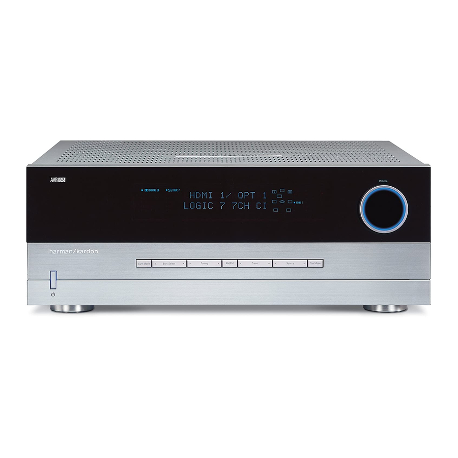
Page 5: Front Panel Controls
Front Panel Controls Main Power Switch System Power Control Power Indicator Headphone Jack Surround Mode Group Selector Speaker Selector Button ‹ Tone Mode Surround Mode Selector Tuning Selector Tuner Band Selector 1 Main Power Switch: Press this button to apply power to the AVR. When the switch is pressed in, the unit is placed in a Standby mode, as indicated by the orange LED 3 surrounding the System Power Control 2. - Page 6 Front Panel Controls 9 Surround Mode Selector: Press this button to cycle through the individual surround modes available after the Surround Mode Group Selector 5 was pressed (see item 5 above). Note that depending on the type of input, some modes are not always available. (See page 38 for more information about surround modes).
-
Page 7: Rear Panel Connections
Rear Panel Connections AM Antenna FM Antenna Tape Inputs Tape Outputs Main Subwoofer Output DVD Audio Inputs CD Inputs Multiroom Audio Outputs A-BUS Connector 8-Channel Direct Inputs Digital Audio Outputs Video Monitor Outputs DVD Video Inputs Front Speaker Outputs Center Speaker Outputs Surround Speaker Outputs Switched AC Accessory Outlet NOTE: To assist in making the correct connec-... - Page 8 AVR 645. This connection is also used to connect a compatible computer to the AVR for firmware upgrades, when available. See page 43 for more information on playback of computer audio with the AVR.
- Page 9 AVR 645 will automatically send a low-volt- age signal to the connected device that turns it on when the AVR 645 is on and off when the AVR 645 is placed in the Standby Mode. The connected component must respond to 6-volt presence as the control signal.
-
Page 10: Main Remote Control Functions
Main Remote Control Functions Power Off Button IR Transmitter Window LCD Information Display Power On Button Input Selectors AVR Selector AM/FM Tuner Select 6-Channel/8-Channel Direct Input Test Button Sleep Button Surround Mode Selector Night Mode Channel Select Button Dim Button Navigation Button Set Button Digital Select... - Page 11 Main Remote Control Functions IMPORTANT NOTE: The AVR 645’s remote may be programmed to control up to seven devices, including the AVR. Before using the remote, it is important to remember to press the Input Selector button that corresponds to the unit you wish to operate.
- Page 12 Disc Skip Button: This button has no direct function for the AVR 645 but may be used to change the disc in a CD or DVD changer when the remote is programmed for that type of...
- Page 13 Main Remote Control Functions Preset Up/Down: When the tuner is in use, press these buttons to scroll through the sta- tions programmed into the AVR’s memory. When CD or DVD is selected using the Input Selector button , these buttons may function as Slow Fwd/Rev (DVD) or ”+10”...
-
Page 14: Zone Ii Remote Control Functions
We strongly recommend that the ZR 10 remote be used for the initial configuration and setup process for the AVR 645. A Power Off: When used in the room where the AVR is located, press this button to place the unit in Standby. - Page 15 J Blank Buttons: These buttons are not active. Pressing them will not change or control any function on the AVR 645 or other IR devices. K Mute: When used in the room where the AVR is located, press this button to temporarily silence the unit.
-
Page 16: Installation And Connections
Installation and Connections After unpacking the unit, and placing it on a solid surface capable of supporting its weight, you will need to make the connections to your audio and video equipment. Audio Equipment Connections We recommend that you use high-quality inter- connect cables when making connections to source equipment and recorders to preserve the integrity of the signals. -
Page 17: Video Connections
Digital or DTS audio is not available on the HDMI connection, it will be necessary to make an additional connection between the source Ó and the AVR 645 to either the Coaxial * Digital Inputs. or Optical • HDMI 1.1 sources carry the multichannel digi- tal audio output from DVD-Audio players in addition to the digital video. -
Page 18: Scart A/V Connections
Connect the HDMI Output to an HDMI input on your video display. Thanks to the AVR 645’s video processing system, all video input signals are converted to an HDMI output, so only one connection is required between the AVR and your display. - Page 19 Installation and Connections Figure 1: SCART/Cinch-Adapter for playback; signal flow: SCART → Cinch Figure 2: SCART/Cinch-Adapter for record and playback; signal flow: SCART ↔ Cinch Black Black Figure 3: Yellow Yellow Cinch/SCART-Adapter for playback; signal flow: Cinch → SCART Figure 4: SCART/S-Video Adapter for playback;...
-
Page 20: System And Power Connections
Installation and Connections System and Power Connections The AVR 645 is designed for flexible use with multiroom systems, external control components and power amplifiers. Main Room Remote Control Extension If the receiver is placed behind a solid or smoked glass cabinet door, the obstruction may prevent the remote sensor from receiving commands. -
Page 21: Speaker Selection
Installation and Connections USB Connections The AVR 645 is one of the few A/V receivers to offer a USB connection that may be used for both playback of compatible audio content from a computer and for loading of system updates (when available). - Page 22 Installation and Connections Note: The 6.1-channel configuration is not rec- ommended for the AVR. We strongly recommend a 7.1-channel installation as described below. When 6.1-channel materials are played through a 7.1-channel system, the same surround back channel information is played through both the left and right surround back speakers.
-
Page 23: System Configuration
You are now ready to power up the AVR 645 to begin these final adjustments. First Turn On You are now ready to power up the AVR to begin these final adjustments. - Page 24 System Configuration Before using the unit, you will probably want to change the settings for some inputs so that they are properly configured to reflect the use of digi- tal or analog inputs and the surround mode associated with the input. Remember that since the AVR memorizes the settings for each input individually, you will need to make these adjust- ments for each input used.
- Page 25 The second page of the IN/OUT SETUP menu (Figure 9) allows you to further configure the AVR 645 for special custom features. I N / O U T S E T U P →...
-
Page 26: Video Monitor Settings
(Figure 10) is unique in that it contains a mix of information display lines that detail status information about the AVR 645’s video system settings, along with a few lines where a specific parameter may be changed. With the... -
Page 27: Surround Setup
System Configuration Surround Setup The next step for that input is to set the surround mode you wish to use with that input. Since sur- round modes are a matter of personal taste, feel free to select any mode you wish – you may change it later. - Page 28 This includes not only PCM sources from DVD or CD players, but also all two-channel analog sources that are in use, as they are converted to PCM within the AVR 645. The modes available include the proprietary Dolby modes (including Dolby Headphone and Dolby Virtual Speaker), DTS processing, our own Logic 7 modes, the conventional “DSP”...
-
Page 29: Night Mode Settings
Set Button MASTER MENU Q to return to the main menu so that you may move to the next step in configuring your AVR 645. Using EzSet/EQ The AVR uses Harman Kardon’s EzSet/EQ tech- nology to automatically configure your system to... - Page 30 System Configuration Step 2. Select one of the two options shown based on the way you wish to have the system settings entered: • In most cases, you will want to use the Automatic mode, which calibrates the system for speaker presence, speaker “size”, speaker crossover, channel output level, speaker-to- listener delay time and room equalization.
- Page 31 System Configuration Step 7a. If the measurements are not successful due to a missing or malfunctioning speaker, the message will FAR FIELD E Q ERROR appear as shown in Figure 17e. EzSet/EQ is pro- grammed to look for speaker pairs at the front left/front right, surround left/surround right and surround back left/surround back right positions.
-
Page 32: Manual Setup
However, if you feel that your listen- ing room or system components are best suited to manual entry of these settings, the AVR 645 also allows you to enter or trim any of these tra- ditional system parameters. Even if you do make... - Page 33 System Configuration that will have on the speaker’s performance. If you do not have access to the owner’s manual for a particular speaker, you should be able to obtain the needed information from the Web site or customer service department of the speaker’s manufacturer.
-
Page 34: Delay Settings
System Configuration Sub Mode Setting When the Front Left/Right speakers are con- figured as “Large” and a subwoofer is detected by EzSet/EQ or manually configured as being available, additional options are available to further customize bass redirection. To change these settings, first make sure that the menu (Figure 19) is on the SPEAKER SIZE screen, and then press the... -
Page 35: Output Level Adjustment
System Configuration To re-synchronize the front, center and surround channels at first measure and note the distance from the listening/viewing position to the front, center, surround and surround back (if any) speakers in meters. If you have already calibrated your system using Ezset/EQ the delay settings shown will reflect the results of the measurements made by Ezset/EQ. - Page 36 System Configuration C HANNEL ADJUST : 0dB SBR : 0dB → C E N : 0dB SBL : 0dB : 0dB : 0dB : 0dB SW1 : 0dB T E ST T ONE: AUTO L E VEL RESET: CH AD JUST: GLOBAL EZ SET SETTINGS: B A CK T O MANUAL SETUP Figure 22...
-
Page 37: Additional Input Adjustments
System Configuration To return to the settings established by Ezset/EQ, even if you have made manual changes to the output trims using the steps shown above, press F so that the Navigation Button ⁄ ¤ cursor is pointing to the EZSET line and then press the SETTINGS... -
Page 38: Operation
Operation Surround Mode Chart MODE FEATURES DOLBY DIGITAL Available only with digital input sources encoded with Dolby Digital data. It provides up to five separate main audio channels and a special dedicated Low Frequency Effects channel. DOLBY DIGITAL EX Available when the receiver is configured for 6.1/7.1 channel operation, Dolby Digital EX is the latest version of Dolby Digital. - Page 39 Operation Surround Mode Chart MODE FEATURES DTS Neo:6 Cinema These two modes are available when any analog source is playing to create a six-channel DTS Neo:6 Music surround presentation from conventional Matrix-encoded and traditional Stereo sources. Select the Cinema version of Neo:6 when a program with any type of analog Matrix surround encoding is present.
-
Page 40: Basic Operation
Operation Basic Operation Once you have completed the setup and configu- ration of the AVR, it is simple to operate and enjoy. The following instructions should be followed for you to maximize your enjoyment of your new receiver: Turning the AVR On or Off •... -
Page 41: Controls And Use Of Headphones
Operation Note that when the 6-Channel or 8-Channel Input is in use, you may not select a surround mode, as the external decoder determines the processing in use. In addition, there is no signal at the record outputs or bass management when the 6-Channel or 8-Channel Direct Input is in use and the tone or balance controls will not function. -
Page 42: Digital Audio Playback
42 OPERATION In order to provide maximum playback compatibility with DVDs, the AVR 645 receiver will always default first to the playback mode embedded in a disc’s digital “flag” information. For Dolby Digital discs, the following playback... -
Page 43: Selecting A Digital Source
AVR. USB Playback The AVR 645 is among the very few A/V receivers capable of direct connection to a computer for audio playback. Once the AVR is connected, audio streams and playback are possible through... -
Page 44: Speaker/Channel Indicators
Operation In addition, you will need to have a media player installed on the computer. The AVR has been tested for operation with Windows Media Player Version 8.0 and above, but it is also compatible with many other popular players such as iTunes ®... -
Page 45: Tape Recording
(e.g. DVD) of the AVR. Additionally, the digital signals will be passed through to the Digital Audio Outputs Using The AVR 645 is equipped for use with Bridge Harman Kardon’s optional iPod docking station. -
Page 46: Output Level Adjustment With Source
Operation Output Level Adjustment With Source Signals Normal output level adjustment for the AVR is established using the test tone, as out- lined on page 36. In some cases, however, it may be desirable to adjust the output levels using program material such as a test disc, or a selec- tion you are familiar with. -
Page 47: Advanced Features
Advanced Features The AVR is equipped with a number of advanced features that add extra flexibility to the unit’s operation. While it is not necessary to use these features to operate the unit, they provide addi- tional options that you may wish to use. Front-Panel-Display Fade In normal operation, the front-panel displays and indicators remain on at full brightness, although... -
Page 48: Semi-Osd Settings
Advanced Features Semi-OSD Settings The semi-OSD system places one line messages at the lower third of the video display screen whenever the Volume, Input Source, Surround mode or tuner frequency of any of the configura- tion settings are changed. The semi-OSD system is helpful in that enables you to have feedback on any control changes or remote commands using the video display when it is difficult to view... -
Page 49: Multiroom Operation
Multiroom Operation Multiroom Operation The AVR is fully equipped to operate as the con- trol center for a complete multiroom system that is capable of sending one source to a second zone in the house while separate source is listened to in the main room. In addition to providing for control over the selection of the remote source and its volume, the AVR offers a comprehensive range of options for powering the... -
Page 50: Infrared Output Selection
Multiroom Operation Infrared Output Selection The AVR enables you to select which IR input will be used to feed the Full Carrier IR Output The factory default setting is the IR signal that is fed to the Multiroom IR Input , but you may select other options. -
Page 51: Tuner Operation
Tuner Operation Basic Tuner Operation The AVR’s tuner is capable of tuning AM, FM and FM Stereo broadcast stations and receiving RDS data. Stations may be tuned manually, or they may be stored as favorite station presets and recalled from a 30 position memory. Station Selection 1. -
Page 52: Program Search
Tuner Operation Program Search (PTY) An important feature of RDS is its capability of encoding broadcasts with Program Type (PTY) codes that indicate the type of material being broadcast. The following list shows the abbreviations used to indicate each PTY, along with an explanation of the PTY: •... -
Page 53: Programming The Remote
Harman Kardon DVD players and changers, CD players and changers, CD recorders and cassette decks. The codes for other brand devices may be programmed into the AVR 645 remote using its extensive library of remote codes or a head-to-head learning process for codes not in the internal library. -
Page 54: Automatic Code Entry
Programming the Remote Although the AVR remote is preprogrammed with an extensive library of codes for many major brands, it is also possible that you may have attempted to program a product that is too new or too old, and thus not all of its commands will be in the code library. -
Page 55: Learning Commands
Step 3. Learning Codes for an Input Selector The AVR 645’s remote allows you to learn a specific code to be attached to one of the Input Selectors so that whenever that button is pressed, you will not only be selecting that device as the AVR’s input and telling the remote... -
Page 56: Macro Programming
Programming the Remote Changing Devices In the factory default settings, the AVR remote is programmed so that the commands transmitted correspond to the device selected by pressing one of the Input Selectors . This is logical, as you want the remote to control the device you have selected. - Page 57 Programming the Remote M A I N M E N U M A C R O Figure 47 3. At the next menu screen (Figure 48) press the Set Button to begin recording a macro. M A C R O R E C O R D A M A C R O Figure 48 4.
-
Page 58: Punch-Through Configuration
Programming the Remote Read a Macro To check the commands stored in the remote’s memory for one of the buttons, follow these steps: 1. Press and hold the Program Button about three seconds while the message shown in Figure 25 appears in the remote’s LCD Information Display . - Page 59 Programming the Remote To program the AVR for Channel punch-through, follow these steps. This example will show how to program channel punch-through so that the commands programmed for Channel Up/Down for the VID 3/ Cable device will be transmitted when the VID 1/VCR device has been selected as the current device.
-
Page 60: Renaming
Programming the Remote Returning the Transport Control Settings to Default Operation: If you wish to remove the Transport Punch- Through so that the transport commands are returned to the factory default setting, follow the steps shown above, except that in Steps 4 and 5, select the same device for both the DEVICE IN USE on the left side of the bottom line and the PUNCH-THROUGH device. -
Page 61: Resetting The Remote
Programming the Remote 3. At the next menu screen press the ⁄¤ Navigation Buttons until RENAME KEY appears on the bottom line of the LCD screen, as shown in Figure 77. Press the Set Button to continue. R E N A M E R E N A M E K E Y Figure 77 4. -
Page 62: Backlight Options
C O M P L E T E Figure 84 Backlight Options The AVR 645’s remote has a built-in backlight system that makes it easier to use the remote when the room lighting is dimmed for an optimal home theater experience. To turn the back- lighting on, simply press the Light Button That button is made from a special “glow”... -
Page 63: Troubleshooting Guide
Troubleshooting Guide SYMPTOM CAUSE Unit does not function when Main • No AC Power Power Switch 1 is pushed Display lights, but no sound • Intermittent input connections or picture • Mute is on • Volume control is down Units turns on, but Front-Panel •... -
Page 64: Appendix
The two tables in this section show the factory default settings for the Video Inputs, Video Sources and Video Display Aspect Ratios. These tables give you the complete picture on the AVR 645’s initial settings. You may then decide whether any item needs to be changed so that it is more appropriate for your specific installation. - Page 65 APPENDIX Worksheet B: Surround Configuration Defaults and Settings Feature System Default Logic 7 Global Default Surround Dolby Pro Logic II Music Center Width Dolby Pro Logic II Music Dimension Dolby Pro Logic II Panorama Dolby Pro Logic IIx Music Center Width Dolby Pro Logic IIx Music Dimension Dolby Pro Logic IIx Panorama Night Mode...
- Page 66 APPENDIX 66 APPENDIX...
-
Page 67: Technical Specifications
Technical Specifications Audio Section Stereo Mode Continuous Average Power (FTC) 90 Watts per channel, 20Hz–20kHz, @ < 0.07% THD, both channels driven into 8 ohms 5/7 Channel Surround Modes Power Per Individual Channel Front L&R channels: 75 Watts per channel, @ <... - Page 68 250 Crossways Park Drive, Woodbury, New York 11797 www.harmankardon.com Harman Consumer Group, Inc.: 2, route de Tours, 72500 Château-du-Loir, France © 2006 Harman Kardon, Incorporated Part No.: ZKD3001HA00-R...