
Related Manuals for Harman Kardon AVR 120


Summary of Contents for Harman Kardon AVR 120
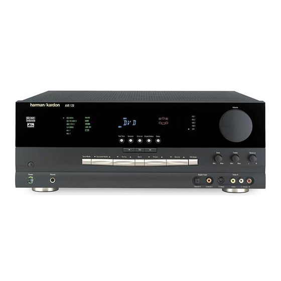
- Page 1 AVR 120 Audio/Video Receiver OWNER’S MANUAL AVR 120 ® ® Power for the Digital Revolution. ™...
-
Page 2: Table Of Contents
AVR 120 Audio/Video Receiver Introduction Safety Information Unpacking Front Panel Controls Front Panel Information Display Rear Panel Connections Remote Control Functions Installation and Connections System Installation Audio Equipment Connections Video Equipment Connections Power Connections System Configuration Speaker Selection and Placement... -
Page 3: Introduction
DVD and LD releases and Digital Television broadcasts. While complex digital systems are hard at work within the AVR 120 to make all of this happen, hookup and operation are simple. Color-keyed connections and a programmable remote control make the AVR 120 easy to use. -
Page 4: Safety Information
Safety Information Important Safety Information Verify Line Voltage Before Use Your AVR 120 has been designed for use with 120-volt AC current. Connection to a line volt- age other than that for which it is intended can create a safety and fire hazard and may damage the unit. -
Page 5: Front Panel Controls
System Power Control: When the Main Power Switch is “ON, ” press this button to turn on the AVR 120; press it again to turn the unit off. Note that the Power Indicator surrounding the switch will turn green when the unit is on. - Page 6 Volume Control: Turn this knob clockwise to increase the volume, counterclockwise to decrease the volume. If the AVR 120 is muted, adjusting the Volume Control will automatically release the unit from the silenced condition.
-
Page 7: Front Panel Information Display
Standby mode. Night Mode Indicator: This indicator lights when the AVR 120 is in the Night mode, which preserves the dynamic range of digital program material at low volume levels. - Page 8 Front Panel Information Display Memory Indicator: This indicator flashes when entering presets and other information into the tuner’s memory. Stereo Indicator: This indicator lights when an FM station is being tuned in stereo. Tuned Indicator: This indicator lights when a station is being received with sufficient signal strength to provide acceptable listening quality.
-
Page 9: Rear Panel Connections
fl Switched AC Accessory Outlet ‡ Unswitched AC Accessory Outlet ° AC Power Cord · Video 1 Video Outputs a Video 1 Video Inputs ° AC INPUT ~120V/60HZ A MODEL NO. AVR 120 – SERIAL NO. RIGHT LEFT SURR. SPKRS (8 ) fi fl... - Page 10 fl Switched AC Accessory Outlet: This outlet may be used to power any device you wish to have turned on when the AVR 120 is turned on with the System Power Control Switch ‡ Unswitched AC Accessory Outlet: This outlet may be used to power any AC device.
-
Page 11: Remote Control Functions
TV/Video Selector Mute NOTE: The function names shown here refer to each button’s feature when used with the AVR 120. Most buttons have additional func- tions when used with other devices. See pages 31–32 for a list of these functions. POWER... - Page 12 Input Selectors: Pressing one of these buttons will perform three actions at the same time. First, if the AVR 120 is not turned on, this will power up the unit. Next, it will select the source shown on the button as the input to the AVR 120.
- Page 13 (See page 28 for more information on storing and recalling macros.) Transport Controls: These buttons do not have any functions for the AVR 120, but they may be programmed for the forward/ reverse play operation of a wide variety of CD or DVD players, and audio or video cassette recorders.
-
Page 14: Installation And Connections
If your speakers have color-coded connections, match the termi- nal on the AVR 120 to the like terminal on your speakers. For existing speakers with a red termi- nal for the positive connection, the connections... -
Page 15: Power Connections
AC outlet. Finally, when all connections are complete, plug the Power Cord ° into a nonswitched 120-volt AC wall outlet. You’re almost ready to enjoy the AVR 120! 15 INSTALLATION AND CONNECTIONS... -
Page 16: System Configuration
Once the speakers have been placed in the room and connected, the remaining steps in the setup process are to program the AVR 120’s bass management system for the type of speakers used in your system, calibrate the output levels, and set the delay times used... -
Page 17: System Setup
System Configuration You are now ready to power up the AVR 120 to begin these final adjustments. 1. Plug the Power Cord ° into an unswitched AC outlet. 2. Press the Main Power Switch in until it latches and the word “OFF” on the top of the switch disappears inside the front panel. -
Page 18: Output Level Adjustment
. When this option is selected, all bass information will be routed to the front left/right “main” speakers. • If a subwoofer is connected to the AVR 120, you have the option to have the front left/right “main” speakers reproduce bass... -
Page 19: Delay Settings
For accurate calibration, it is a good idea to make these adjustments while seated in your favorite listening position: 1. Put the AVR 120 in the Dolby Pro Logic II mode by pressing Surround Mode Selector on the front panel, or by... -
Page 20: Additional Input Adjustments
System Configuration To set the delay times, follow these steps: 1. Put the AVR 120 in the Dolby Pro Logic II mode by pressing the Surround Mode Selector on the front panel or by pressing the Surround Mode Selector on the remote, until PRO LOGIC II... -
Page 21: Operation
Turning the AVR 120 On or Off • When using the AVR 120 for the first time, you must press the Main Power Switch on the front panel to turn the unit on. This places the... -
Page 22: Surround Mode Chart
Operation Surround Mode Chart MODE FEATURES DOLBY DIGITAL Available only with digital input sources encoded with Dolby Digital data. It provides up to five separate main audio channels and a special dedicated Low-Frequency Effects channel. Available only with digital input sources encoded with DTS data. Available on special DVD, LD and audio-only discs, DTS provides up to five separate main audio channels and a special dedicated low-frequency channel. -
Page 23: Surround Mode Selection
LD discs. Note that an optional, external RF demodulator is required to use the AVR 120 to listen to the Dolby Digital sound tracks available on laser discs. Connect the RF output of the LD player to... -
Page 24: Digital Status Indicators
“Audio Select” button or in a menu screen on the disc) to send a full 5.1 feed to the AVR 120. It is also possible for the type of sig- nal feed to change during the course of a DVD playback. -
Page 25: Mp3 Audio Playback
MP3 Audio Playback The AVR 120 is one of the few A/V receivers to provide on-board decoding for the MP3 audio format used by computers and portable audio devices. In addition, some new CD players are... -
Page 26: Tape Recording
Preset Tuning Using the remote, up to 30 stations may be stored in the AVR 120’s memory for easy recall using the front panel controls or the remote. To enter a station into the memory, first tune the station using the steps outlined above. -
Page 27: Programming The Remote
Auto Search Method. Auto Search Method If the unit you wish to include in the AVR 120’s remote is not listed in the code tables in this manual or if the code does not seem to operate... -
Page 28: Macro Programming
Macros enable you to easily repeat frequently used combinations of commands with the press of a single button on the AVR 120 remote con- trol. Once programmed, a macro will send out up to 19 different remote codes in a predeter-... -
Page 29: Punch-Through Programming
TV viewing, you may wish to have the AVR 120’s volume activated, although the remote is set to run the TV. Either the AVR 120 or TV volume control may be associated with any of the remote’s devices. To program the... -
Page 30: Transport Control Punch-Through
TV, you may wish to start or stop your VCR or DVD without having to change the device selected by the AVR 120 or the remote. To program the remote for Transport Control Punch-Through, follow these steps: 1. -
Page 31: Function List
Function List No. Button Name AVR Function Power Off Power Off Power Off Power On Power On Power On Mute Mute Mute AVR Select DVD Input Select DVD Select CD Input Select Tape Tape Input Select VID1 Video 1 Select VID2 Video 2 Select 10 VID3... - Page 32 Function List (continued) No. Button Name AVR Function 45 Preset Up Preset Tune Up Slow Forward 46 Tune Down Tune Down Prev Chapter Track Increment 47 D. Skip Disc Skip 48 Preset Down Preset Tune Down Slow Rev 49 M1 Open/Close 50 M2 Subtitle On/Off Repeat...
- Page 33 Setup Code Table: TV Manufacturer/Brand Setup Code Number A MARK ADMIRAL AKAI AMPRO ANAM 103 106 123 128 BLAUPUNKT BROKSONIC CANDLE CAPEHART CENTURION CENTRONIC CITIZEN 123 128 CLASSIC CONCERTO CONTEC CORANDO CORONADO CRAIG 157 158 CROWN CURTIS MATHES 128 132 DAEWOO 087 102 DAYTRON...
- Page 34 Setup Code Table: TV (continued) Manufacturer/Brand Setup Code Number 123 128 MINERVA MITSUBISHI 115 123 NATIONAL 177 179 121 123 NIKEI ONKING ONWA OPTONICA ORION 208 209 PANASONIC 148 169 PHILCO 115 123 PHILIPS 128 132 PIONEER 123 128 PORTLAND PROSCAN PROTON 122 128...
- Page 35 Setup Code Table: VCR Manufacturer/Brand Setup Code Number AIWA AKAI 048 108 109 126 AMPRO AUDIO DYNAMICS 018 048 BROKSONIC 110 147 CANDLE 134 135 CANON 135 140 CAPEHART CITIZEN CRAIG 045 116 DAEWOO 017 094 104 DAYTRON 018 048 DYNATECH EMERSON 013 040 042 110 112...
- Page 36 Setup Code Table: VCR (continued) Manufacturer/Brand Setup Code Number SALORA SAMSUNG 045 095 105 109 SANSUI 048 116 147 SANYO 017 020 SCOTT 110 112 SEARS 017 020 SHARP 129 156 SONY 080 129 SOUNDESIGN SYLVANIA SYMPHONIC TANDY 017 040 TASHICO TATUNG TEAC...
- Page 37 Setup Code Table: CD Setup Code Table: CD (Continued) Manufacturer/Brand Setup Code Number GENEXXA GOLDSTAR HAITAI HARMAN KARDON 054 190 HITACHI INKEL JC PENNEY JENSEN KENWOOD 079 148 LOTTE LUXMAN MAGNAVOX MARANTZ 192 193 MCINTOSH MITSUMI MODULAIRE NAKAMICHI NIKKO ONKYO 046 171 OPTIMUS 092 099...
- Page 38 Setup Code Table: Tape Manufacturer/Brand Setup Code Number HARMAN KARDON Setup Code Table: DVD Manufacturer/Brand Setup Code Number APEX DIGITAL DENON 019 051 003 004 GOLDSTAR HARMAN KARDON 005 055 064 MAGNAVOX MARANTZ MITSUBISHI ONKYO 009 048 PANASONIC 024 030 044 PHILIPS PIONEER 041 065...
- Page 39 Setup Code Table: SAT Manufacturer/Brand Setup Code Number ALPHASTAR ALPHASTAR DBS ALPHASTAR DSR BIRDVIEW CHANNEL MASTER 320 321 325 361 CHAPARRAL 315 316 CITOH DRAKE 313 317 413 481 DX ANTENNA 331 352 379 483 ECHOSTAR 395 397 453 463 ELECTRO HOME FUJITSU 324 329...
- Page 40 Setup Code Table: CBL Manufacturer/Brand Setup Code Number 001 011 ALLEGRO AMERICAST ARCHER BELCOR CABLE STAR 033 113 CITIZEN COLOUR VOICE 085 090 DIGI EAGLE EASTERN 066 070 ELECTRICORD EMERSON FOCUS G.I. 001 011 017 096 097 GC ELECTRONICS GEMINI 032 060 GENERAL GENERAL INSTRUMENT...
- Page 41 Setup Code Table: CBL (continued) Manufacturer/Brand Setup Code Number REMBRANT SAMSUNG 072 186 SCIENTIFIC ATLANTA 183 203 SEAM SIGNATURE 001 188 SPRUCER 053 081 177 189 STARCOM 002 011 163 STARGATE TANDY TELECAPATION TEXSCAN TIMELESS TOCOM 170 205 UNITED CABLE UNIVERSAL 033 034 039 042 113 VIDEOWAY...
-
Page 42: Troubleshooting Guide
Troubleshooting Guide Your AVR 120 receiver has been designed to provide many years of trouble-free service. In the event that you are experiencing difficulties, please check the suggestions below for a possible solution to your problem. Additional information on the AVR 120, including updated information and user hints, is avail- able from our Web site at www.harmankardon.com. -
Page 43: Technical Specifications
Technical Specifications Audio Section Stereo Mode Continuous Average Power (FTC) 50 Watts per channel, @ < 0.07% THD, 20Hz – 20kHz, both channels driven into 8 ohms Five-Channel Surround Modes Power Per Individual Channel Front L&R channels: 40 Watts per channel @ <... - Page 44 ® 250 Crossways Park Drive, Woodbury, New York 11797 www.harmankardon.com © 2001 Harman Kardon, Incorporated Part No.: J90200012410...