Table of Contents
Advertisement
Advertisement
Table of Contents

Related Manuals for MSI MS-7324


Summary of Contents for MSI MS-7324
- Page 1 945G Series MS-7324 (v1.X mATX Mainboard)
-
Page 2: Fcc-B Radio Frequency Interference Statement
VOIR LA NOTICE D’INSTALLATION AVANT DE RACCORDER AU RESEAU. Micro-Star International MS-7324 This device complies with Part 15 of the FCC Rules. Operation is subject to the following two conditions: (1) this device may not cause harmful interference, and... -
Page 3: Trademarks
Copyright Notice T he material in this document is the intellec tual property of M ICRO-STAR INTERNATIONAL. W e take every care in the preparation of this document, but no guarantee is given as to the correctness of its contents. Our products are under continual improvement and we reserve the right to make changes without notice. -
Page 4: Safety Instructions
Safety Instructions Always read the safety instructions carefully. Keep this User’s Manual for future reference. Keep this equipment away from humidity. Lay this equipment on a reliable flat surface before setting it up. The openings on the enclosure are for air convection hence protects the equip- ment from overheating. -
Page 5: Weee Statement
WEEE Statement... -
Page 8: Table Of Contents
CONTENTS FCC-B Radio Frequency Interference Statement ..........ii Copyright Notice ......................iii Tra dema rks ......................... iii Technical Support ...................... iii Revision History ......................iii Safety Instructions ....................iv WEEE Statement ......................v Chapter 1. Getting Started ..................1-1 Mainboard Specifications ................... 1-2 Mainboard Layout .................... - Page 9 Front Panel Connectors: JF_P1 ..............2-18 Front USB Connectors: JUSB1~2 ............2-19 Front Panel Audio Connector: JAUD1 ............2-19 IEEE 1394 Connector: J1394_1 ..............2-20 S/PDIF-Out Connector: SPDOUT1 ............2-20 Jumpers ......................2-21 Clear CMOS Jumper: JBAT1 ..............2-21 Slots ........................2-22 PCI Express Slots (optional) ..............
-
Page 10: Chapter 1. Getting Started
Getting Started Chap t er 1 . Ge tting Started Getting Started Thank you for choosing the 945G Series (MS-7324) v1.X ® mATX mainboard. The 945G Series mainboard is based on Intel ® 945G and Intel ICH7DH chipset for optimal system efficiency. De- ®... -
Page 11: Mainboard Specifications
M S-7324 mATX Mainboard Mainboard Specifications † ® Supports Intel Pentium 4/ Celeron D Prescott LGA775 processors up to 945W (Prescott, Cedar Mill, Presler, Conroe and Smithfield) in LGA775 package. † Supports 2005 Performance FMB CPU VR Design. † Supports 3/4 pin CPU Fan Pin-Header with Fan Speed Control. Chipset †... - Page 12 Getting Started - 1 parallel port supports SPP/EPP/ECP mode - 1 Front-Out / SS-Out / Line-In / BS-Out / CB-Out - 1 SPDIF-Out/In (Coaxial) / SPDIF-Out/In (Optical) - 8 USB ports (Rear * 4/ Front * 4) - 1 RJ-45 LAN jack †...
-
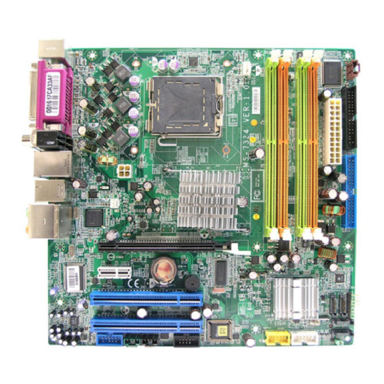
Page 13: Mainboard Layout
T: 1394 B: USB Ports SYS_F1 T: Front -Out M: SS -Out PCI E_X16 Line-In T: CB-Out M: Back-Out PCI E_X1 BATT PCI 1 PCI 2 Codec SATA2 JUSB1 JUSB2 JAUD1 JSCA1JL_IN1 J1394_1 SATA1 JBAT1 945G Series (MS-7324) v1.X mATX Mainboard... -
Page 14: Chapter 2. Hardware Setup
Hardware Setup Chapter 2. Hardware Setup Hardware Setup This chapter tells you how to install the CPU, memory modules, and expansion cards, as well as how to setup the jumpers on the mainboard. Also, it provides the instructions on connecting the periph- eral devices, such as the mouse, keyboard, etc. -
Page 15: Quick Components Guide
M S-7324 mATX M ainboard Quick Components Guide CPU_FAN1 CPU, CPU_FAN2, DIMM1~4, p.2-3 p.2-14 p.2-7 Back Panel, JVFD1, p.2-10 p.2-18 FDD1, p.2-14 JPW1, ATX1, p.2-9 p.2-9 SPDOUT1, p.2-20 IDE1, SYS_FAN1, p.2-15 p.2-14 PCI-E Slots, p.2-22 PCI Slots 1~2, p.2-23 JF_P1, p.2-18 SATA1~4, p.2-16... -
Page 16: Central Processing Unit: Cpu
Hardware Setup Central Processing Unit: CPU ® The mainboard supports Intel Pentium 4 Prescott processor. The mainboard uses a CPU socket called LGA775. W hen you are installing the CPU, make sure to install the cooler to prevent overheating. If you do not have the CPU cooler, contact your dealer to purchase and install them before turning on the computer. -
Page 17: Cpu & Cooler Installation
M S-7324 mATX M ainboard CPU & Cooler Installation W hen you are installing the CPU, make sure the CPU has a cooler attached on the top to prevent overheating. Meanwhile, do not forget to apply some thermal paste on CPU before installing the heat sink/cooler fan for better heat dispersion. Follow the steps below to install the CPU &... - Page 18 Hardware Setup 5. Lift the load lever up and open the 6. After confirming the CPU direction load plate. for correct mating, put down the CPU in the socket housing frame. Be sure to grasp on the edge of the CPU base. Note that the align- ment keys are matched.
- Page 19 M S-7324 mATX M ainboard 9. Press down the load lever lightly 10. Align the holes on the mainboard onto the load plate, and then se- with the heatsink. Push down the cure the lever with the hook under c ooler u nti l i ts f ou r c lip s g et retention tab.
-
Page 20: Memory
Hardware Setup Memory The mainboard provides 4 slots for 240-pin DDR2 DIMM, which supports the memory size up to 4GB. Since DDR2 modules are not interchangeable with DDR1 and the DDR2 stand- ard is not backward compatible, you should always install DDR2 memory module in the DDR2 slot (DIMM1~DIMM4). -
Page 21: Installing Ddr2 Modules
M S-7324 mATX M ainboard ORANGE GREEN ORANGE GREEN DIMM1 (Ch A) DIMM2 (Ch B) DIMM3 (Ch A) DIMM4 (Ch B) System Density 256MB~1GB 256MB~1GB 512MB~2GB 256MB~1GB 256MB~1GB 512MB~2GB 256MB~1GB 256MB~1GB 512MB~2GB 256MB~1GB 256MB~1GB 512MB~2GB 256MB~1GB 256MB~1GB 256MB~1GB 256MB~1GB 1GB~4GB - Dual-channel DDR works ONLY in the 5 combinations listed in the table shown in the previous page. -
Page 22: Power Supply
Hardware Setup Power Supply The mainboard supports ATX power supply for the power system. Before inserting the power supply connector, always make sure that all components are installed properly to ensure that no damage will be caused. ATX 24-Pin Power Connector: ATX1 This connector allows you to connect an ATX 24-pin power supply. -
Page 23: Back Panel
M S-7324 mATX M ainboard Back Panel The back panel provides the following connectors: S/PDIF-In S/PDIF-Out Front-Out Parallel M ou se 1394 BS-Out SS-Out CB-Out Line-In Keyboard Opt-In Opt-Out USB Ports Mouse/Keyboard Connector ® The mainboard provides a standard PS/2 mouse/keyboard mini DIN connector ®... -
Page 24: Usb Connectors
Hardware Setup USB Connectors The mainboard provides an OHCI (Open Host Controller Interface) Universal Serial Bus root for attaching USB devices such as keyboard, mouse or other USB- compatible devices. You can plug the USB device directly into the connector. USB Port Description SIGNAL DESCRIPTION... -
Page 25: Audio Port Connectors
M S-7324 mATX M ainboard Audio Port Connectors The left 3 audio jacks are for 2-channel mode for stereo speaker output: Front Out is a connector for Speakers or Headphones. Line In is used for external CD player, Tape player, or other audio devices. However, there is an advanced audio application provided by Realtek ALC882 to offer support for 7.1-channel audio operation and can turn rear audio connectors from 2-channel to 4-/5.1-/7.1- channel audio. -
Page 26: Parallel Port Connector: Lpt1
Hardware Setup Parallel Port Connector: LPT1 The mainboard provides a 25-pin female centronic connector as LPT. A parallel port is a standard printer port that supports Enhanced Parallel Port (EPP) and Ex- tended Capabilities Parallel Port (ECP) mode. Pin Definition SIGNAL DESCRIPTION STROBE... -
Page 27: Connectors
M S-7324 mATX M ainboard Connectors The mainboard provides connectors to connect to FDD, IDE HDD, case, LAN, and USB Ports. Floppy Disk Drive Connector: FDD1 The mainboard provides a standard floppy disk drive connector that supports 360K, 720K, 1.2M, 1.44M and 2.88M floppy disk types. FDD1 Fan Power Connectors: CPU_FAN1/CPU_FAN2/SYS_FAN1 The CPU_FAN1/CPU_FAN2 (processor fan), SYS_FAN1 support system cool-... -
Page 28: Hard Disk Connector: Ide1
Hardware Setup Hard Disk Connector: IDE1 The mainboard has one 32-bit Ultra DMA 66/100 IDE controller integrated in the chips Intel ICH7R, which supports PIO & Bus Master operation modes and it can connect up to two Ultra ATA drives. IDE1 (blue) If you install two hard disks on cable, you must configure the second drive to Slave mode by setting its jumper. -
Page 29: Serial Ata Connectors Controlled By Intel Ich7: Sata1~4
M S-7324 mATX M ainboard Serial ATA Connectors controlled by Intel ICH7: SATA1~4 The SouthBridge of this mainboard is Intel ICH7 which supports four serial ATA connectors SATA1~4. SATA1~4 are dual high-speed Serial ATA interface ports. Each supports 1 generation serial ATA data rates of 150 MB/s. Both connectors are fully compliant with Serial ATA 1.0 specifications. -
Page 30: Front Line-In Connector: Jl_In1
Hardware Setup Front Line-In Connector: JL_IN1 The connector is for front line-in connector. JL_IN1 SCART Output Connector: JSCA1 The JSCA1 connector allows you to connect the output device with SCART spec. SCART is the established European standard for connecting home video equip- ments like TVs, VCRs, DVD players, etc. -
Page 31: Front Lcd Moduke Header: Jvfd1
M S-7324 mATX M ainboard Front LCD Module Header: JVFD1 The connector allows you to connect to Medion VFD LCD panel. +5VSB Front Panel Connectors: JF_P1 The mainboard provides one front panel connector for electrical connection to ® the front panel switches and LEDs. JF_P1 is compliant with Intel Front Panel I/O Connectivity Design Guide. -
Page 32: Front Usb Connectors: Jusb1~2
Hardware Setup Front USB Connectors: JUSB1~2 The mainboard provides two standard USB 2.0 pin headers JUSB1~2. USB 2. 0 technology increases data transfer rate up to a maximum throughput of 480Mbps, which is 40 times faster than USB 1.1, and is ideal for connecting high-speed USB interface peripherals such as USB HDD, digital cameras, MP3 players, printers, modems and the like. -
Page 33: Ieee 1394 Connector: J1394_1
M S-7324 mATX M ainboard IEEE 1394 Connector: J1394_1 The mainboard provides one 1394 pin header that allow you to connect optional IEEE 1394 port. Pin Definition SIGNAL SIGNAL TPA+ TPA- Ground Ground TPB+ TPB- J1394_1 Cable power Cable power Key (no pin) Ground S/PDIF-Out Connector: SPDOUT1... -
Page 34: Jumpers
Hardware Setup Jumpers The motherboard provides the following jumper for you to set the computer’s function. This section will explain how to change your motherboard’s function through the use of jumper. Clear CMOS Jumper: JBAT1 There is a CMOS RAM on board that has a power supply from external battery to keep the system configuration data. -
Page 35: Slots
M S-7324 mATX M ainboard Slots The mainboard provides a PCI Express x16 slot, a PCI Express x1 slot and three 32-bit PCI bus slots. PCI Express Slots (optional) The PCI Express slots, as a high-bandwidth, low pin count, serial, intercon- nect technology, support Intel highest performance desktop platforms utilizing the Intel Pentium 4 processor with HT Technology. -
Page 36: Pci (Peripheral Component Interconnect) Slots
Hardware Setup PCI (Peripheral Component Interconnect) Slots The PCI slots allow you to insert the expansion cards to meet your needs. W hen adding or removing expansion cards, make sure that you unplug the power supply first. Meanwhile, read the documentation for the expansion card to make any necessary hardware or software settings for the expansion card, such as jumpers, switches or BIOS configuration.