
Subscribe to Our Youtube Channel
Related Manuals for Panasonic WV-CM143


Summary of Contents for Panasonic WV-CM143
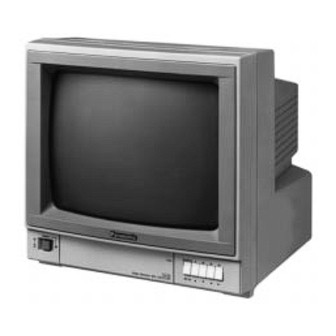
- Page 1 Colour Monitor WV-CM143 Before attempting to connect or operate this product, please read these instructions completely...
- Page 2 If you lose the fuse cover the plug must not be used until a replacement TO REDUCE THE RISK OF ELECTRIC SHOCK, cover is obtained. DO NOT REMOVE COVER (OR BACK), NO USER A replacement fuse cover can be purchased from your local Panasonic SERVICEABLE PARTS INSIDE. Dealer. REFER SERVICING TO QUALIFIED SERVICE IF THE FITTED MOULDED PLUG IS UNSUITABLE FOR THE SOCK- PERSONNEL.
-
Page 3: Table Of Contents
CONTENTS PREFACE ......................................1 FEATURES ......................................1 PRECAUTIONS ....................................1 MAJOR OPERATING CONTROLS AND THEIR FUNCTIONS ......................2 OPERATING PROCEDURES ................................5 SETUP OPERATION ................................... 9 CONNECTION ....................................12 SYSTEM CONNECTION ..................................16 SPECIFIACATIONS .................................... 18 The model numbers listed in this Operating Instructions have no suffixed attached to it. -
Page 4: Preface
• As many as 4 Solid State Colour Cameras can be con- VTR. nected to Colour Monitor WV-CM143 with an alarm fea- • Automatic bypass circuit for skipping no camera con- ture. This Colour Cameras can be added by using the nection. -
Page 5: Major Operating Controls And Their Functions
MAJOR OPERATING CONTROLS AND THEIR FUNCTIONS FRONT VIEW POWER SEQUENCE 1 PUSH SET UP Video Monitor WV-CM STAND BY CAMERA MIN. .MAX MODE INPUT V-HOLD TINT COLOR COLOR BRIGHT CONTRAST PICTURE AUDIO SELECT 1. Power Switch (POWER) 5. Vertical Hold Control (V-HOLD) This is a push-push type switch which turns the power This control is used to adjust the picture in vertically. -
Page 6: Rear View
9. Bright Subcontrol and turn this control counterclockwise to decrease the audio level. 10. Contrast Control (CONTRAST) Turn this control clockwise to increase the picture con- 14. Sequence / Setup Selection Switch (SEQUENCE / trast and turn this control counterclockwise to SETUP) Press this switch more than 2 seconds to display the decrease the picture contrast. - Page 7 STANDBY-GND Connection 27. Camera Input Connectors (CAMERA INPUT, 1/2/3/4) The connected buzzer or chime will sound when The BNC type connectors are used to provide the the Mode Selection Switch is positioned at video output signal of the cameras to the additional STANDBY and the intercom or alarm is activated.
-
Page 8: Operating Procedures
OPERATING PROCEDURES 4. Set the desired sequential switching interval time with the Set Up menu. POWER SEQUENCE 1 STAND BY CAMERA MIN. .MAX V-HOLD MODE INPUT COLOUR BRIGHT CONTRAST PICTURE AUDIO SELECT SET UP Note: The sequential switching features the automatic bypass circuit by detecting the presence of the Selection of Camera DC power for the camera so that the input connec-... - Page 9 Priority of SPOT MONITOR CONTROL IN The selection of the camera by SPOT MONITOR CONTROL IN is set as first come, first served. The Camera Selection Switch has a first priority against the selection signal. VTR Playback Mode 1. Set the Power Switch (1) to the ON position by press- ing once.
- Page 10 1. SETUP MENU This monitor utilizes various user setup menu by using the on-screen character display. This setup menu is shown in the following. This menu is described in the following section 3 “SETUP MENU DESCRIPTION” in detail. SET UP menu SETUP DISABLE SETUP ENABLE Camera...
- Page 11 3-3. Timing Selection (TIMING SELECT) 3-7. Automatic Reset On/Off Setting (AUTO RESET) ** SET UP MENU ** ** SET UP MENU ** CAMERA ID 1 2 3 4 CAMERA ID 1 2 3 4 1 CAMERA 1 CAMERA AUDIO SELECT AUDIO SELECT TIMING SELECT TIMING SELECT...
-
Page 12: Setup Operation
SETUP OPERATION Editing Set Up menu Before entering the Set Up menu, remember the ALL RESET operation in order to escape from the confusion as follows. ** SET UP MENU ** (1) Confirm that the Mode Selection Switch (3) is set to the CAMERA ID 1 2 3 4 1 CAMERA... - Page 13 Setting Procedure 1-1. Move the cursor to the CAMERA ID and select the desired camera by using the Left (A)(17) or Right (B)(18) Switch. To set the Camera ID Display On/Off mode, press the Setup Switch 1. Camera Identification Setting (14).
- Page 14 4. Sequential Time Adjustment 7. Auto Reset Setting (AUTO RESET) (SEQ TIME ADJ) ** SET UP MENU ** CAMERA ID 1 2 3 4 ** SET UP MENU ** 1 CAMERA AUDIO SELECT CAMERA ID 1 2 3 4 TIMING SELECT 1 CAMERA SEQ TIME ADJ 1 SEC...
-
Page 15: Connection
2. Keep the power switch of the monitor , optional camera, optional camera extension unit and in the OFF position during the con- nection. Connection with camera Camera Colour Monitor WV-CM143 TIMING SELECT ALARM SPOT MONITOR CONTROL IN REMOTE OUT... - Page 16 • Connect the camera extension cable from the camera extension unit Camera Extension Input TIMING SELECT: INT Connector on the monitor. • Camera Extension Units can be connected up to 31 Colour Monitor WV-CM143 units. TIMING SELECT ALARM SPOT MONITOR CONTROL IN REMOTE OUT CONTROL RECOVER STDBY...
- Page 17 Connection with the VTR Colour Monitor WV-CM143 Note: Avoid the following connection when monitoring the playback picture of VTR. TIMING SELECT ALARM SPOT MONITOR CONTROL IN REMOTE OUT CONTROL RECOVER STDBY RESET FOCUS MODE AUDIO OUT AUDIO IN CAMERA CAMERA INPUT...
- Page 18 Do not connect the intercom system of AC power source. Two modes for the Alarm Control Out are selected. STD BY: This terminal is performed at only Standby mode of the Mode Selection Switch when the SPOT MONI- TOR CONTROL IN is activated by intercom or alarm sensor/switch.
-
Page 19: System Connection
Camera 3 Camera 4 Intercom 1 Setup Menu Setting is; TIMING SELECT Intercom 2 AUTO RESET Coaxial Cable Intercom 4 Intercom 3 Ground Colour Monitor WV-CM143 TIMING SELECT ALARM SPOT MONITOR CONTROL IN REMOTE OUT CONTROL RECOVER STDBY RESET FOCUS MODE... - Page 20 1. When the alarm signal operation will be made in this as shown below. system Connect the Time Date Generator according to 4. The Colour Monitor WV-CM143 (B) can not connect to the need. the camera. 5. The Colour Monitor WV-CM143 (A) does not allow the 2.
-
Page 21: Specifications
SPECIFICATIONS Power Source: WV-CM143/A, WV-CM143/B, WV-CM143/G: 220-240V AC 50 Hz Power Consumption: Approx. 110W CRT Size: 36.8 cm (14" diagonal) Actual Visual Size: 33.5 cm (13" diagonal) Camera Input: 1.0 Vp-p/75 ohms, composite 4 (BNC) Video Input: 1.0 Vp-p/75 ohms, composite... - Page 22 Matsushita Electric Industrial Co., Ltd. Central P.O. Box 288, Osaka 530-91, Japan N1095-3026 YWV8QA4090DN Printed in Japan N 13 Gedruckt in Japan Imprimé au Japon Impreso en Japón...
Need help?
Do you have a question about the WV-CM143 and is the answer not in the manual?
Questions and answers