Table of Contents
Advertisement
Available languages
Available languages
INSTALLATION I NSTRUCTIONS 6 00 CFM AND
1200CFM IN-LINEBLOWERS FORRANGEHOODS
INSTRUCTIONS D 'INSTALLATION VENTILATEURS
INTERNES A VEC DEBIT D.E 600 PPET1200PPPOUR
HOTTES D'EVACUATION
Table of Contents/Table des mati_res
IN-LINE BLOWER SAFETY ...........................................................
1
...............................................
3
Tools and Parts ............................................................................
3
Location Requirements ...............................................................
3
Venting Requirements .................................................................
4
Electrical Requirements ...............................................................
5
.................................................
6
Prepare Location .........................................................................
6
Make Electrical Connection .........................................................
7
ASSISTANCE OR SERVICE ..........................................................
9
In the U.S.A ..................................................................................
9
In Canada ....................................................................................
9
WARRANTY ..................................................................................
10
SECURITE DU VENTILATEUR INTERNE ............................. 11
..............................................
13
Outils et pieces ......................................................................
13
Exigences d'emplacement ....................................................
13
Exigences concernant I'evacuation ...................................... 14
Specifications electriques .....................................................
15
D'INSTALLATION ........................................
16
Preparation de I'emplacement ..............................................
16
Raccordement electrique ......................................................
17
ASSISTANCE OU SERVICE ....................................................
19
Au Canada .............................................................................
19
GARANTIE ................................................................................
20
IN-LINEBLOWER SAFETY
Your safety and the safety of others are very important.
We have provided many important safety messages in this manual and on your appliance. Always read and obey all safety
messages.
This is the safety alert symbol.
This symbol alerts you to potential hazards that can kill or hurt you and others.
All safety messages will follow the safety alert symbol and either the word "DANGER" or "WARNING."
These words mean:
You can be killed or seriously injured if you don't immediately
follow
instructions.
You can be killed or seriously injured if you don't follow
instructions.
All safety messages will tell you what the potential hazard is, tell you how to reduce the chance of injury, and tell you what can
happen if the instructions are not followed.
IMPORTANT: READ AND SAVE THESE INSTRUCTIONS.
FOR RESIDENTIAL
USE ONLY.
iMPORTANT : URE ET CONSERVER CES iNSTRUCTIONS.
POUR UTILISATION
RI_SIDENTIELLE
UNIQUEMENT.
LI3ZDA / W10331013A
Advertisement
Table of Contents

Related Manuals for Whirlpool UXI0600DYS


Summary of Contents for Whirlpool UXI0600DYS
-
Page 1: Table Of Contents
INSTALLATION I NSTRUCTIONS 6 00 CFM AND 1200CFM IN-LINEBLOWERS FORRANGEHOODS INSTRUCTIONS D 'INSTALLATION VENTILATEURS INTERNES A VEC DEBIT D.E 600 PPET1200PPPOUR HOTTES D'EVACUATION Table of Contents/Table des mati_res SECURITE DU VENTILATEUR INTERNE ......11 IN-LINE BLOWER SAFETY ............INSTALLATION REQUIREMENTS .......... - Page 2 iMPORTANT SAFETY iNSTRUCTiONS WARNING: TO REDUCE THE RISK OF A RANGE TOP WARNING: TO REDUCE THE RISK OF FIRE, ELECTRIC GREASE FIRE: SHOCK, OR INJURY TO PERSONS, OBSERVE THE FOLLOWING: [] Never leave surface units unattended at high settings. Boilovers cause smoking and greasy spillovers that may [] Use this unit only in the manner intended by the ignite.
-
Page 3: Installation Requirements
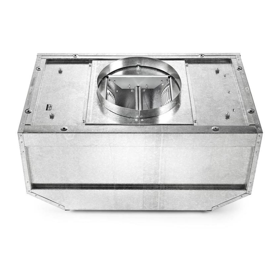
INSTALLATION REQUIREMENTS Gather the required tools and parts before starting installation. IMPORTANT: Observe all governing codes and ordinances. Read and follow the instructions provided with any tools listed Have a qualified technician install the in-line blower motor here. system. All openings in the ceiling and wall where the in-line blower motor Tools needed system will be installed must be sealed. -
Page 4: Venting Requirements
The vent system must terminate to the outdoors. Typical In-line Blower System Installations Do not terminate the vent system in an attic or other enclosed area. A 10" (25.4 cm) round vent system is needed for installation (not • Do not use 4" (10.2 cm) laundry-type vent or wall caps. included). -
Page 5: Electrical Requirements
Calculating Vent System Length Observe all governing codes and ordinances. To calculate the length of the system you need, add the equivalent length for each vent piece used in the system. Ensure that the electrica( insta(lation is adequate and in conformance with Nationa( Electrical Code, ANSI/NFPA 70 (latest Vent Piece... -
Page 6: Installation Instructions
INSTALLATION INSTRUCTIONS P i pc:;ssst Pull the spring clip to release the blower motor assembly. Before making cutouts, make sure there is proper clearance Remove the blower motor assembly from the housing and within the ceiling or wall for the exhaust vent. place it on a covered surface. -
Page 7: Make Electrical Connection
4. If removed, reinstall the blower motor assembly and secure it Mc <® Eecff ccl Connec with the screws previously removed. 5. If removed, reattach the motor electrical plug to the connector on the blower motor assembly. Complete Preparation Determine and make all necessary cuts for the vent system. IMPORTANT: When cutting or drilling into the ceiling or wall, do not damage electrical wiring or other hidden utilities. - Page 8 4. Run the wire ends from the 6-wire connector assembly through the 1/2"(1.3 cm) strain relief, leaving enough wire length to make the wiring connections. Tighten the strain relief screws. 5. Connect the wires from the 6-wire connector assembly to the wires from the wiring conduit inside the range hood terminal box.
-
Page 9: Assistanceor Service
When calling for assistance or service, please know the purchase date and the complete model and serial number of your If you need further assistance, you can write to Whirlpool appliance. This information will help us to better respond to your Corporation with any questions or concerns at: request. -
Page 10: Warranty
YOU SPECIFIC LEGAL RIGHTS, AND YOU MAY ALSO HAVE OTHER RIGHTS WHICH VARY FROM STATE TO STATE OR PROVINCE TO PROVINCE. If outside the 50 United States and Canada, contact your authorized Whirlpool dealer to determine if another warranty applies. If you need service, first see the "Troubleshooting"... -
Page 11: Securite Du Ventilateur Interne
SECURITE DU VENTILATEUR INTERNE Votre securite et celle des autres est tres importante. Nous donnons de nombreux messages de s_curit_ importants dans ce manuel et sur votre appareil m_nager. Assurez-vous toujours lire tous les messages de s_curit_ et de vous y conformer. Ce symbole d'alerte de s_curit_ vous signale les dangers potentiels de d_c_s et de blessures graves &... - Page 12 llVIPORTANTES iNSTRUCTiONS DE SI CURITI AVERTISSEIVIENT : POUR MINIMISER LE RISQUE AVERTISSEMENT : POUR REDUIRE LE RISQUE D'UN FEU DE GRAISSE SUR LA CUISINIERE D'INCENDIE, CHOC ¢:LECTRIQUE OU DOMMAGES CORPORELS, RESPECTER LES INSTRUCTIONS [] Ne jamais laisser un 616ment de surface fonctionner & SUIVANTES puissance de chauffage maximale sans surveillance.
-
Page 13: Exigencesd'installation
EXIGENCESD'INSTALLATION Rassembler les outils et composants nicessaires avant IMPORTANT : Observer les dispositions de tousles codes et d'entreprendre I'installation. Lire et observer les instructions reglements en vigueur. fournies avec chacun des outils de la liste ci-dessous. Flecourir a un technicien qualifie pour installer le systeme de ventilation interne. -
Page 14: Exigences Concernant I'evacuation
• Le systeme d'evacuation doit decharger I'air & I'exterieur. Installations typiques d'un syst_me de ventilation interne • Ne pas terminer le circuit d'evacuation dans un grenier ou dans un autre espace clos. Un circuit d'evacuation en conduit rond de 10" (25,4 cm) est •... -
Page 15: Specifications Electriques
Calcul de la Iongueur effective du circuit d'_vacuation Observer les dispositions de tous les codes et reglements en Pour calculer la Iongueur effective du circuit d'evacuation vigueur. necessaire, additionner les Iongueurs equivalentes (en pieds ou metres) de tous les composants utilises dans le circuit. -
Page 16: Instructions D'installation
INSTRUCTIONS D'INSTALLATION Avant d'effectuer des decoupes, s'assurer que I'espace est 5. Tirer sur la languette & ressort pour degager I'ensemble suffisant sur lemur ou le plafond pour le conduit moteur-ventilateur. Retirer I'ensemble moteur-ventilateur d'evacuation. Iogement et le placer sur une surface couverte. Lors des operations de decoupe et de per£_age dans un mur ou un plafond, veiller &... -
Page 17: Raccordement Electrique
4. Si I'ensemble moteur-ventilateur a et6 retire, le reinstaller et le fixer avec les vis retirees auparavant. 5. Si la prise electrique du moteur a et6 debranch6e, rebrancher au connecteur de I'ensemble moteur-ventilateur. Achever la preparation 1. Determiner et effectuer toutes les decoupes necessaires pour le passage du circuit d'evacuation. - Page 18 Faire passer les conducteurs du connecteur & 6 ills & travers le serre-c&bles de 1/2"(1,3 cm), en laissant une Iongueur suffisante pour le raccordement. Serrer les vis du serre-c&ble. Raccorder les conducteurs du connecteur & 6 ills avec ceux du conduit de c&blage a I'interieur du boftier de connexion de la hotte.
-
Page 19: Assistance Ou Service
I'appareil. Ces renseignements nous aideront & Veuillez appeler sans frais le Centre pour I'eXperience de la mieux repondre a votre demande. clientele de Whirlpool Canada LP au : 1-800-807-6777. Nos consultants vous renseigneront sur les sujets suivants •... -
Page 20: Garantie
& moins que ces dommages soient dus & des vices de materiaux ou de fabrication et soient signales & Whirlpool dans les 30 jours suivant la date d'achat. Toute perte d'aliments due & une defaillance du refrig6rateur ou du congelateur.