
Related Manuals for Moxa Technologies IA261


Summary of Contents for Moxa Technologies IA261
- Page 1 IA261/262 Hardware User’s Manual Fourth Edition, December 2009 www.moxa.com/product © 2009 Moxa Inc. All rights reserved. Reproduction without permission is prohibited.
-
Page 2: Copyright Notice
Information in this document is subject to change without notice and does not represent a commitment on the part of Moxa. Moxa provides this document “as is,” without warranty of any kind, either expressed or implied, including, but not limited to, its particular purpose. Moxa reserves the right to make improvements and/or changes to this manual, or to the products and/or the programs described in this manual, at any time. -
Page 3: Table Of Contents
Table of Contents Chapter 1 Introduction ....................1-1 Overview..........................1-2 Package Checklist ........................1-2 Product Features ........................1-3 Product Hardware Specifications..................... 1-4 Hardware Block Diagram ......................1-6 Chapter 2 Hardware Introduction.................2-1 Appearance ..........................2-2 Dimensions (unit = mm) ......................2-3 LED Indicators......................... 2-4 Reset Button.......................... -
Page 4: Chapter 1 Introduction
SCADA, manufacturing automation and other industrial applications. This manual introduces the hardware of the IA261/262 series embedded computers. After a brief introduction of the hardware features, the manual focuses on installation and hardware configuration with device interfaces. -
Page 5: Overview
This space-saving solution also facilitates easy wiring, and is the best choice of front-end embedded controller for industrial applications. Due to its VGA output capability, IA261/262 is not only play the role of protocol conversion or data acquisition for the field site devices, it is also suitable for SCADA system in industrial... -
Page 6: Product Features
RISC-based Embedded Computer with VGA, 2 Serial Ports, Dual LANs, CAN, DIO, CompactFlash, USB, Linux, Wide Temperature, isolation protection for all IO All models of the IA261/262 series are shipped with the following items: 1 IA261/262 Embedded Computer Wall-Mounting Kit DIN-Rail Mounting Kit (attach to the product’s casing) -
Page 7: Product Hardware Specifications
Protection: built-in 1.5KV magnetic isolation protection Serial Communicaiton Serial Port: IA261: RS-232/422/485 x 4, software-selectable IA262: RS-232/422/485 x 2, software-selectable RS-232 signals: TxD, RxD, DTR, DSR, RTS, CTS, DCD, GND RS-422 signals: TxD+, TxD-, RxD+, RxD-, GND 4-wire RS-485 signals: TxD+, TxD-, RxD+, RxD-, GND... - Page 8 10M/Link x 2 (on connector), 100M/Link x 2 (on connector) Serial: TxD x 4, RxD x 4 IA261: P1 ~ P4 for serial ports IA262: P1 ~ P2 for serial ports, P3 ~ P4 for CAN ports Power Requirements Power Input:...
-
Page 9: Hardware Block Diagram
IA261/262 Hardware User’s Manual Introduction Hardware Block Diagram IA-261 Ethernet x 2 USB 2.0 Host x 2 Controller Power Circuit 128MB Power Circuit 32MB Cirrus Logic EP9315 Flash 32-bit ARM9 200 MHz Function UART Watchdog MOXA MOXA MOXA MOXA UART... - Page 10 IA261/262 Hardware User’s Manual Introduction IA-262 Ethernet x 2 USB 2.0 Host x 2 Controller Power Circuit 128MB Power Circuit 32MB Cirrus Logic EP9315 Flash 32-bit ARM9 200 MHz Function UART Watchdog MOXA MOXA CANBus UART UART Controller ASIC ASIC...
-
Page 11: Chapter 2 Hardware Introduction
The LED indicators allow users to monitor performance and identify trouble spots quickly, and the multiple ports can be used to connect a variety of devices. The IA261/262 comes with a reliable and stable hardware platform that lets you devote the bulk of your time to application development. -
Page 12: Appearance
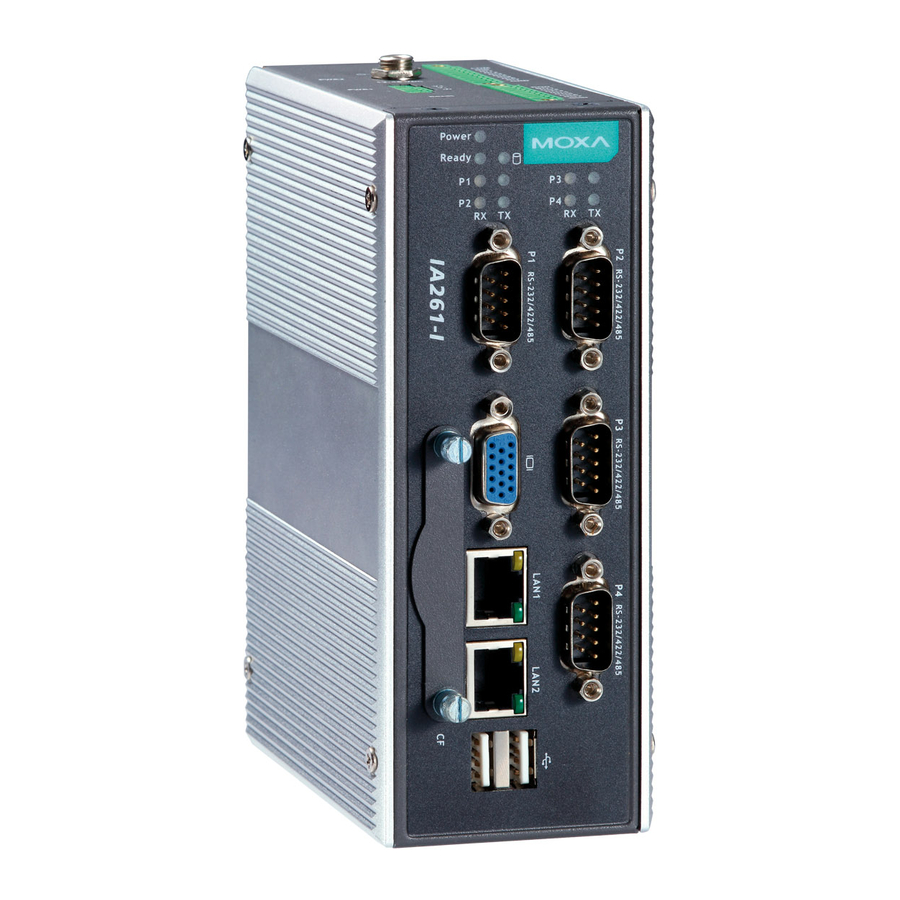
IA261/262 Hardware User’s Manual Hardware Introduction Appearance Top View Power Input 1 DI x 8 Power Input 2 DO x 8 Reset Button Front View LED Indicators Power, Ready, Storage Power LED Indicators Ready Serial, Tx/Rx LED Indicators CANBus, Tx/Rx... -
Page 13: Dimensions (Unit = Mm)
IA261/262 Hardware User’s Manual Hardware Introduction Dimensions (unit = mm) 57.55 46.10 11.35 60.15 13.70 42.35 8.80 38.05 11.10 19.10 11.10... -
Page 14: Led Indicators
Serial/CAN port is not receiving RX data to the serial device. Reset Button The IA261/262 has one reset button located on the top panel. This button can be used to do a simple Reset, which involves switching the power off and then switching the power back on again. -
Page 15: Real Time Clock
DIN-Rail Mounting The aluminum DIN-Rail attachment plate is already attached to the product’s casing. To attach the plate to IA261/262, make sure that the stiff metal spring is facing the top of the IA261/262, as shown in the following figures. -
Page 16: Wall Mounting (Optional)
Hardware Introduction Wall Mounting (optional) For some applications, you will find it convenient to mount the IA261/262 on the wall. However, we strongly recommend that you use DIN-Rail mounting for the IA261/262 computer when installing at field sites that encounter high levels of vibration and shock. -
Page 17: Hardware Connection Description
Hardware Connection Description Chapter 3 This section describes how to connect the IA261/262 to a network and various devices for first time testing purposes. We cover Wiring Requirements, Connecting the Power, Grounding the IA261/262, Connecting to the Network, Connecting to a Serial Device, Connecting to a CAN device, connecting to the Console Port, VGA, CompactFlash Socket, USB, and DI/DO. -
Page 18: Wiring Requirements
Connecting the Power The IA261/262 provide 2 kinds of power input, a screw power jack and a 3-pin terminal block, both of which allow 12 to 48 VDC power input. The two power inputs can be used to provide a redundant power solution. -
Page 19: Grounding The Unit
IA261/262 Hardward User’s Manual Hardware Connection Description Terminal Block Screw Power Jack ATTENTION The power for this product is intended to be supplied by a Listed Power Supply Unit that is rated to deliver 12 to 48 VDC at a minimum of 1200 mA for 12 VDC, and 260 mA for 48 VDC. -
Page 20: Connecting To The Console Port
Hardware Connection Description Connecting to the Console Port The IA261/262’s console port is a 4-pin pin-header RS-232 port. It is designed for serial console terminals, which are useful for identifying the boot up message, or for debugging when the system cannot boot up. -
Page 21: Connecting To A Keyboard And Mouse
Use properly wired serial cables to connect the IA261/262 to serial devices. The serial ports of the IA261 (P1 to P4) and IA262 (P1 to P2) use male DB9 connectors. The ports can be configured by software for RS-232, RS-422, or 2-wire RS-485. The precise pin assignments are shown in the... -
Page 22: Connecting To A Can Device
CAN-H Connecting to the DI/DO The IA261/262 has an 8-ch digital input and 8-ch digital output, both of which support 3 KV optical isolation protection. The digital input channels and digital output channels are located on the top side of the unit and output by terminal block. The pinouts for the I/O are shown in the figure. -
Page 23: Digital Input Wiring
Note: If you are using wet contacts, you must connect “COM” to power. Digital Output Wiring Insert CompactFlash Card The IA261/262 have a built-in CompactFlash socket. The CompactFlash socket allows users to add additional memory by inserting a CompactFlash memory card, without any risk to the computer. - Page 24 IA261/262 Hardward User’s Manual Hardware Connection Description 3. Be sure to insert the CompactFlash card correctly into the protective cover, as shown in the figure below. 4. Insert the CompactFlash protective cover with the CompactFlash card into the socket, as shown in the figure.
-
Page 25: Usb Hosts
IA261/262 Hardward User’s Manual Hardware Connection Description ATTENTION The IA261/262 does not support CompactFlash hot swap and PnP (Plug and Play) function. It is necessary to remove power source first before inserting or removing the CompactFlash card. USB Hosts The IA261/262 provides 2 USB 2.0 full speed hosts (OHCI), type A connectors, which support a... -
Page 26: Appendix A Regulatory Approval Statements
Regulatory Approval Statements Appendix A This device complies with part 15 of the FCC Rules. Operation is subject to the following two conditions: (1) This device may not cause harmful interference, and (2) this device must accept any interference received, including interference that may cause undesired operation.
Need help?
Do you have a question about the IA261 and is the answer not in the manual?
Questions and answers