Table of Contents
Advertisement
Quick Links
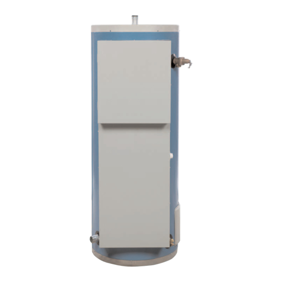
COMMERCIAL ELECTRIC WATER HEATER
INSTALLATION AND OPERATING INSTRUCTIONS
Read and understand these instructions thoroughly before attempting
TABLE OF CONTENTS
Introduction . . . . . . . . . . . . . . . . . . . . . . . . . . . .2
Component Identification . . . . . . . . . . . . . . . . . .3
Recovery Rates . . . . . . . . . . . . . . . . . . . . . . . . .4
Installation . . . . . . . . . . . . . . . . . . . . . . . . . . . .5-9
Electrical . . . . . . . . . . . . . . . . . . . . . . . . . . .10-17
Operation . . . . . . . . . . . . . . . . . . . . . . . . . . . . .18
Maintenance . . . . . . . . . . . . . . . . . . . . . . . .19-21
Leakage Checkpoints . . . . . . . . . . . . . . . . . . . .22
Floor Sealing . . . . . . . . . . . . . . . . . . . . . . . . . .23
Warranty . . . . . . . . . . . . . . . . . . . . . . . . . . . . . .24
PLEASE RETAIN THESE INSTRUCTIONS IN A
SAFE LOCATION FOR FUTURE REFERENCE
WARNING:
Improper installation, adjustment, alter-
ation, service, or maintenance can cause
injury or property damage. Refer to this
manual. For assistance or additional infor-
mation, consult a qualified installer, serv-
ice agency, or the electric utility.
FOR YOUR SAFETY
• Do not store or use gasoline or other
flammable vapors and liquids in the
vicinity of this or any other appliance.
• Installation and service must be per-
formed by a qualified installer, service
agency or the electric utility.
WARNING:
If the information in these instructions is
not followed exactly, a fire or explosion
may result causing property damage, per-
sonal injury or death.
GSW Water Heating is a division of GSW Water Products Inc.
GSW WATER HEATING
599 Hill Street West
Fergus, ON, Canada N1M 2X1
any installation or service.
All models are listed
by Underwriters'
Laboratories, Inc.
INSTALLATION RECORD
This water heater is protected by a three (3) year warranty against
leaks plus a one (1) year warranty on parts.
Record key data here for future reference and prompt service:
Installed By / Purchased From:
Installation Date:
Model Number
Volts
Watts/Element
Number of Elements Watts-Total
Technical Support Line: 1-888-479-8324
Location of Electrical Switch
or Circuit Protector:
Serial Number
Volume
PART NO. 73992 REV. A (05-03)
Advertisement
Table of Contents

Subscribe to Our Youtube Channel
Related Manuals for GSW 73992


Summary of Contents for GSW 73992
-
Page 1: Table Of Contents
All models are listed by Underwriters’ Laboratories, Inc. GSW Water Heating is a division of GSW Water Products Inc. any installation or service. This water heater is protected by a three (3) year warranty against leaks plus a one (1) year warranty on parts. -
Page 2: I) Introduction
It is your responsibility to ensure that your water heater is properly installed and cared for. Important Consumer Notice The warranty on this water heater is in effect only when the water heater is installed and operated in accordance with these instructions. The manufacturer of this water heater will not assume any liability for any injury or property dam- age resulting from failure to comply with these instructions. -
Page 3: Ii) Component Identification
II) COMPONENT IDENTIFICATION ANODE (UNDER PLASTIC CAP) POWER TRANSFORMER (IF APPLICABLE) FUSES (CONTROL CIRCUIT) FUSES (POWER CIRCUIT) (IF APPLICABLE) CONTACTORS PLUGS HEATING ELEMENTS COLD WATER INLET FIGURE 1: Parts Locations CONTROL COMPARTMENT ELEMENT COMPARTMENT NOTES: 1. COVERS REMOVED FOR CLARITY. 2. -
Page 4: Iii) Recovery Rates
III) RECOVERY RATES Standard BTU/Hr KW Input 20,478 30,717 40,956 13.5 46,075 51,195 61,434 81,912 1242 92,151 1397 1045 102,390 1552 1162 122,868 1862 1397 1117 40.5 138,226 2097 1582 1257 1049 153,585 2328 1745 1397 1162 184,302 2794 2093 1677 1397 1196 1049 Standard BTU/Hr KW Input... -
Page 5: Iv) Installation
3. It is suggested that the heater be located in the center of the water system or close to the point-of-use requiring the most hot water. 4. The water heater should be located in an area not sub- ject to freezing temperatures. 5. Water heaters located in unconditioned spaces (i.e., attics, basements, etc.) may require insulation of the... -
Page 6: Unpacking The Water Heater
This is particular- ly important if the water heater is installed in a multi-story building, on finished flooring or carpeted surfaces. GSW WILL NOT ASSUME ANY LIABILITY for damage caused by water leaking from the water heater, pressure relief valve, or related fittings. -
Page 7: Electrical Connections
Contact a licensed plumber or the local plumbing supplier. 4. If installing the water heater in a closed water system, install an expansion tank in the cold water line as speci- fied under “Closed System/Thermal Expansion”. -
Page 8: Installation Check List
If the heater is located a long distance away from the electrical supply, the wire size of the branch circuit should be increased. The voltage measured at the heater should not be less than 3% lower than what is meas- ured at the supply. -
Page 9: Temperature Control
All electric water heaters feature fully automatic controls to regulate the water temperature. The thermostat supplied with the water heater may be either an immersion or a sur- face mounted type. Both types of thermostats use contact relays to energize the electric heating elements. The ther- mostats are located in the bottom control panel. -
Page 10: V) Electrical
V) ELECTRICAL No. of Element KW Input Elements Wattage 2000 3000 4000 13.5 4500 5000 6000 3000 4000 4500 5000 6000 4000 40.5 4500 5000 6000 TABLE 2: Load Currents No. of Element KW Input Elements Wattage 2000 3000 4000 13.5 4500 5000... - Page 11 INPUT TERMINAL BLOCK 3A FUSE 3A FUSE FOR 3 ELEMENTS CONFIGURATION. ONLY C1 WITH CORRESPONDING WIRING APPLIES. FOR 6 ELEMENTS CONFIGURATION. ONLY C1, C2 WITH CORRESPONDING WIRING APPLIES. FOR 9 ELEMENTS CONFIGURATION. CIRCUIT IS AS SHOWN. FIGURE 5: Control Circuit (Canada) INPUT TERMINAL BLOCK...
- Page 12 CONTACTORS FIGURE 7: 6 Element, 1 Phase Power Circuit (Canada) TERMINAL CONTACTORS FIGURE 8: 6 Element, 3 Phase Power Circuit (Canada) INPUT TERMINAL BLOCK LOWER ELEMENTS BLACK BLACK BLACK CENTER ELEMENTS YELLOW BLACK INPUT BLOCK CENTER ELEMENTS - 12 - BLACK BLUE LOWER ELEMENTS...
- Page 13 CONTACTORS UPPER ELEMENTS FIGURE 9: 9 Element, 1 Phase Power Circuit (Canada) TERMINAL BLOCK CONTACTORS FIGURE 10: 9 Element, 3 Phase Power Circuit (Canada) INPUT TERMINAL BLOCK BLACK BLACK BLACK CENTER ELEMENTS BLACK BLACK BLACK YELLOW BLACK INPUT LOWER ELEMENTS CENTER ELEMENTS - 13 - BLACK...
- Page 14 INPUT TERMINAL BLOCK 3A FUSE 3A FUSE FIGURE 11: 3 Element Control Circuit (USA only) TERMINAL (SINGLE PHASE) * REPLACE FUSES WITH SAME SIZE, TYPE AND RATING ONLY. FIGURE 12: 3 Element Power Circuit (USA only) CONTROL TRANSFORMER PRIMARY SECONDARY 480V 240V 208V...
- Page 15 INPUT TERMINAL BLOCK 3A FUSE 3A FUSE FIGURE 13: 6 Element Control Circuit (USA only) TERMINAL (SINGLE PHASE) * REPLACE FUSES WITH SAME SIZE, TYPE AND RATING ONLY. FIGURE 14: 6 Element Power Circuit (USA only) CONTROL TRANSFORMER PRIMARY SECONDARY 480V 240V 208V...
- Page 16 INPUT TERMINAL BLOCK 3A FUSE 3A FUSE CONTACTORS FIGURE 15: 9 Element Control Circuit (USA only) TERMINAL (SINGLE PHASE) * REPLACE FUSES WITH SAME SIZE, TYPE AND RATING ONLY. FUSE HOLDER WITH FUSES * CONTACTORS UPPER ELEMENTS FIGURE 16: 9 Element Power Circuit (USA only) CONTROL TRANSFORMER PRIMARY...
- Page 17 460V 230V 208V FIGURE 17: Transformer PT75MLI (USA only) 600V 480V 416V 240V FIGURE 19: Transformer PT75MRMA (USA only) 380V 277V 208V SECONDARY 115V, 0.65A FIGURE 18: Transformer PT75MGJ (USA only) SECONDARY 0.63A 120V 130V - 17 - SECONDARY 120V, 0.63A...
-
Page 18: Vi) Operation
4. Open the cold water supply valve. NOTE: When filling, avoid water leakage. Do not allow the insulation of the water heater to get wet as water can cause electrical malfunction. 5. When water runs out of the hot water faucet in a steady stream, the tank is full. -
Page 19: Vii) Maintenance
“Startup” when heater is ready to be put back into serv- ice. NOTE: If the water heater is going to be shut down for an extended period, drain the tank as directed in “Draining, Flushing and Sediment Removal”. Ensure that the cold water supply valve is closed and the drain valve left open. -
Page 20: Troubleshooting Checklist
DANGER! BE SURE TO TURN OFF THE POWER TO THE HEATER WHEN CHECKING EQUIPMENT. Insufficient or no hot water: 1. Ensure the electrical supply to the water heater is in the "ON" position. 2. Check that all the fuses are intact;... - Page 21 Follow the instruc- tions given in “Draining, Flushing and Sediment Removal”. 2. Some of the electrical components of the water heater controls make noises. • Most of these are normal. Contactors will "click" or snap as the heater starts and stops, transformers and con- tacts often hum.
-
Page 22: Viii) Leakage Checkpoints
VIII) LEAKAGE CHECKPOINTS ANODE (UNDER PLASTIC CAP) PLUGS FOR UNUSED ELEMENT LOCATIONS COLD WATER INLET FIGURE 21: Possible leakage points HOT WATER OUTLET - 22 - T&P VALVE ELEMENTS CLEANOUT PORT (BEHIND ACCESS DOOR) DRAIN VALVE... -
Page 23: Ix) Floor Sealing
2. Thoroughly read and understand the installation instruc- tion manual supplied with the heater before beginning the installation. 3. Ensure the water heater has been installed in accor- dance with the installation instructions for this water heater and/or with local codes and ordinances. -
Page 24: Warranty
GSW will not assume any expense or liability for unauthorized returns, nor repairs made by a person who has not been authorized by GSW or one of its authorized dealers. GSW Units/parts must be replaced with GSW or John Wood products to be eligible for Warranty.
Need help?
Do you have a question about the 73992 and is the answer not in the manual?
Questions and answers