Table of Contents
Advertisement
OWNER'S MANUAL INDEX
Band Saw Machine Tool
Contents of this binder:
X Material Safety Data Sheets
X Machine Operation and Maintenance Manual . . . . . . . . . . . . . . . . . . . . . . . . 900427
X Safety Manual . . . . . . . . . . . . . . . . . . . . . . . . . . . . . . . . . . . . . . . . . . . . . . . . 900401
X Band Saw Blade Selection and Application Manual . . . . . . . . . . . . . . . . . . . . 900409
X Drive Gear Reduction Bulletin, Cone Drive . . . . . . . . . . . . . . . . . . . . . . . . . . . . FL-1
X Barfeed Layout . . . . . . . . . . . . . . . . . . . . . . . . . . . . . . . . . . . . . . . . Drawing 447140
X Machine Layout . . . . . . . . . . . . . . . . . . . . . . . . . . . . . . . . . . . . . . . . Drawing 446817
X Metering Valve Assembly . . . . . . . . . . . . . . . . . . . . . . . . . . . . . . . . . Drawing 010370
X Drive Assembly . . . . . . . . . . . . . . . . . . . . . . . . . . . . . . . . . . . . . . . . Drawing 448170
X Blade Tension Assembly . . . . . . . . . . . . . . . . . . . . . . . . . . . . . . . . . Drawing 446915
X Guide Assembly 1¼" Blade . . . . . . . . . . . . . . . . . . . . . . . . . . . . . . . Drawing 446807
X Blade Brush Assembly . . . . . . . . . . . . . . . . . . . . . . . . . . . . . . . . . . . Drawing 610805
Hydraulic Chip Conveyor Layout (Option) . . . . . . . . . . . . . . . . . . . Drawing 447350
X System Hydraulics Diagram (Basic Machine) . . . . . . . . . . . . . . . . . . Drawing 019632
X System Electrical Diagram . . . . . . . . . . . . . . . . . . . . . . . . . . . . . . . . Drawing 020452
Barfeed Holddown Layout (Option) . . . . . . . . . . . . . . . . . . . . . . . . Drawing 1014700
Saw Vise Holddown (Option) . . . . . . . . . . . . . . . . . . . . . . . . . . . . . . Drawing 447118
X Door Safety Interlock Key
X Operation VCD
Machine Serial Number:
Date Shipped:
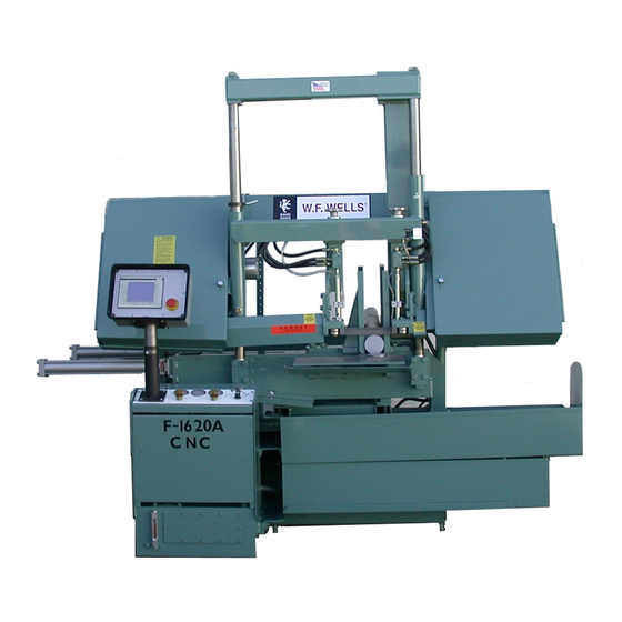
MODEL F-1620-A CNC
Advertisement
Table of Contents

Summary of Contents for W.F. Wells L F-1620-A CNC
- Page 1 OWNER'S MANUAL INDEX Machine Serial Number: Date Shipped: Band Saw Machine Tool MODEL F-1620-A CNC Contents of this binder: X Material Safety Data Sheets X Machine Operation and Maintenance Manual ......900427 X Safety Manual .
- Page 2 2) Tooling, matched to the work piece. 3) Operator, trained and conscientious. A. Site Preparation. W. F. Wells provides the machine tool. See the contents page for the machine floor layout print, with recommended anchoring Consult a reliable blade supplier for the procedure.
- Page 3 2. Set the sawing unit frame over the See maintenance section IV, page 12. anchor bolts in the foundation, screw jacks on the steel plate. 2. Electric hook-up. See maintenance section IV, page 21, and motor rotation direction after hook-up. Vise Cylinders The saw and barfeed cylinders have been removed...
- Page 4 check all level readings. 7. Keep hands away from the blade after it is installed. 7. Tighten nuts on the anchor bolts through the saw frame. B. Operator Controls. 8. Dam around each screw jack and CNC SAW OPERATION pour grout up to the base of the machine to The following is a quick start guide to begin prevent shifting.
- Page 5 manual show each touch screen and contain important factor. the help screen for each as well. The For fast, smooth sawing and lower cost per operator should look at each screen and cut, request a reliable blade supplier make read the help instructions before operation. test cuts on the machine and the work piece with his recommended blades.
- Page 6 For maximum safety and for support of the and select "Off" on their respective switches. blade while sawing, move the left guide arm If an outboard vise or a holddown is used, close to, but not touching the left vise jaw. and the trim-cut material is too short to Allow a half inch extra space to open the clamp, leave the outboard selectors in the...
- Page 7 cycles except the saw head. The saw will weld. Automatic blade welders will get out of complete the cut, return to the raised adjustment, or an inexperienced welder position and the system will shut down, just operator may improperly anneal the weld. as the machine functions with a manual cut.
- Page 8 thrust screws. will not move, or come down only slowly. See the maintenance section for a blade 3) Turn the rear screw in first, bringing it up guide inspection. to the column. Push gently on the frame to feel contact with the post. e) Silt will by-pass a plugged hydraulic fluid filter and accumulate in the metering valve.
- Page 9 Hydraulic fluid temperature over 130° is a Add fresh oil as necessary to bring the level malfunction. Check the fluid level. W. F. Wells and Cone Drive-Textron use and Check the fluid for proper viscosity. recommend using only Mobil SHC-634...
- Page 10 synthetic oil. 2. Water soluble oils. It is normal for gear reducers to operate at Water soluble oils offer good cooling as well housing temperatures up to 200 degrees. as good lubrication. Keep finned areas on the case clean to allow Use one part oil to fifteen parts water for maximum heat dissipation.
- Page 11 blade tension. h) Open the blade guides with the thumb lever cap screws in the face of the guides. b) Raise the saw head so the guide arms One guide at a time, grasp the blade firmly clear the vise jaws. each side of the guide, twist the teeth down and bring the back edge of the blade up between the guide blocks.
- Page 12 a) a. To adjust the tension wheel, see The blade is running too close to the wheel flange, scrubbing, the wheel rim too far from the contents page for the tension assembly the frame plate on the outside. Turn both print and Figure 3.
- Page 13 2) If the blade is running too far from the The supplier will install his gauge on the wheel flange, the wheel rim low on the blade. outside, too close to the frame plate, see Tension the blade. "A," Figure 4, below, turn both threaded When the needle on the control console dial spacers, equally, top and bottom of the case reaches the green dot, the blade supplier will...
- Page 14 piece. If the tensioned blade only partly returns Use preventive maintenance. when pushed down out of the guides, Check the sawing force. without hanging up, continue this check. Linkage travel must not be less than .030" a. Tension the blade, spread the guide and not more than .040".
- Page 15 added to the linkage, or, guide blocks blade wheel and guide. binding the blade. Go to the next step for a blade guide inspection. (5) If feeler gauges read correct, or if the tensioned blade only partly returns when pushed down out of the rollers and there is 6.
- Page 16 b. Horizontal guide adjustment. nut and adjust the plate and blade into alignment with the blade wheels, square to It is critical when making this check to align the vise jaws 90° to the saw bed. the vise jaws. Use the combination square against the blade and vise jaws to check the alignment.
- Page 17 check. See machine voltage, labeled on the electric Particles flaking from walls of hydraulic lines cabinet door. See the contents page for the may have accumulated in the sawing force electric print. system. Check the change date on the hy- draulic fluid filter cartridge.
- Page 18 gram them into inventory on a replace-as- activate the valve, replace the frozen valve. used basis. See spare parts. 2,000 hours is equal to one eight hour shift Also, see optional equipment possibilities. working for one year. Account for spare parts. Enter them into 4.
- Page 19 MODEL F-1620-A CNC Recommended Spare Parts List Group I, 2,000 Hours Part# Description 900091 Blade brush. 901023 Blade brush bearing. 908965 Blade drive belt. 901204 Blade guide rollers, 1¼" blade. 292290 Blade backup slipper, carbide 292420 Blade guide side inserts, 1¼" blade 911231 Hydraulic system filter cartridge.
- Page 20 The following recommendations are for nominal clean operations. Consider shop conditions and machine use when wiping oil on exposed areas. Saw blade and guide lubrication depends on a properly functioning coolant distribution system. Check the coolant pump screens often to be sure they are clean and in place. Clean the coolant pan and change or filter the coolant often, depending on coolant type and machine use.
- Page 21 Material Safety Data Sheets W. F. Wells Incorporated supplies the following Material Safety Data Sheets, furnished us by the original manufacturer of the product, as a material used in our equipment of manufacture. Responsibility for accuracy of information therein rests with the manufacturer of the product.
- Page 22 90 0 2 1 7 WASHER 95 0 0 5 1 S EAL 90 0 2 1 1 91 0 0 3 8 W. F. WELLS WAS HER 95 0 0 5 0 SEAL 4 47 1 5 0 HHCS3 41 0 5 2−16−5...
- Page 24 T O T A N K HHCS1420212 905044 C010294 904113 B 0 1 0 2 9 3 1 . 1 6 0 W . F. Wells drawn by material title Me t e r i n g V a l v e none scale...
- Page 25 B R U S H ONL Y S HAF T NU MB E R 3 0 9 3 9 1 B R U S H AS S Y . W. F. Wells Three Rivers, MI www.wfwells.com A. C. Drive Assembly F−16−2 & F−1620 A CNC...
- Page 26 HHCS38161 4 − 2 0 X 6 HHS & HN 440 460 440 47 0 440 45 0 91 0 1 49 3 " BORE X 3 " S TROKE BL ADE TRAVEL 447 0 4 0 BL ADE 900226 GU ARD Washer 440 48 2...
- Page 27 911500 410710 Ha n d l e Co o l an t Val v e 440390 912673 Was h e r Co o l an t Ho s e 382140 HN1220 440 8 1 0 010296 Co o l a n t Bl o c k 440910 St u d spacer...
- Page 28 B61 0 8 4 A61 0 8 1 5 1 / 2 − 1 3 HN A2 55360 90 0 0 91 W. F. Wells 950 0 0 9 90 1 0 2 3 drawn by material title BLADE BRUSH ASSEMBLY...
-
Page 29: Chip Conveyor
B104855 Section BB A107125 107170 107160 screen 15 Gal HHCS381634 Coolant 931902 Section AA Coolant Pump HHCS12133 HHCS1213212 FW12 HN1213 900202 Wheel B447355 Frame C107970 Conveyor HHCS12131 HN1213 911029 Motor Base C107140 447350 Tank F−1620−A CNC Chip Conveyor... - Page 31 A1014714 PAD A451 422 8" A1014715 PAD A451 421 4" A1014716 PAD ATTACHED WITH 1/4−20 X 3/8 BUTTON HEAD SCREWS − 1 HEX NUT WASHER W. F. Wells title BARFEED HOLDDOWN F−1620−A CNC scale drawing number size rev. 447118 date sym.
- Page 32 W. F. Wells drawn by material F−1620−A CNC title Saw Vise Holddown scale drawing number rev. size 1014700 date sym. revision initial date...
Need help?
Do you have a question about the L F-1620-A CNC and is the answer not in the manual?
Questions and answers