
Summary of Contents for Mitutoyo Measuring Projector
- Page 1 No.99MBA043A SERIES No.302 P J - A 3 0 0 0 Series Measuring Projector User s Manual ’ Read this User's Manual thoroughly before operating the instrument. After reading, retain it close at hand for future reference.
-
Page 2: Safety Precautions
Conventions Used in this User's Manual This section describes the symbols (safety warning symbols) used in this manual. Safety Precautions This manual uses various symbols to help you use this unit correctly, and prevent danger to personnel or equipment damage. •... - Page 3 Risk of injury. Do not place a vessel containing liquid near the instrument. Risk of fire or electric shock. Unplug the power cord and contact Mitutoyo if liquid has entered the instrument. Risk of fire or electric shock. Unplug the power cord if replacing a fuse.
- Page 4 Unplug the power cord if performing maintenance. Do not pull the cable to unplug the power cord. Hold the plug and pull to prevent cord breakage. Risk of fire or electric shock. Do not connect/disconnect or touch the plug with wet hands. Risk of electric shock.
- Page 5 Do not apply excessive force to the instrument. Risk of instrument failure, damage, or decreased accuracy. Only hold the specified parts of the instrument if transporting. Risk of instrument failure, damage, or decreased accuracy. Exercise care so as not to pinch or hurt your fingers if mounting/dismounting accessories.
- Page 6 Mitutoyo assumes no liability to any party for any loss or damage, dir ect or indirect, caused by use of this instrument not conforming to thi s manual. Information in this document is subject to change without notice.
-
Page 7: Handling Precautions
This system has been manufactured under Mitutoyo's rigorous quality control system. In the event that it proves defective in workmanship or materials within one year of the date of purchase under normal usage, Mitutoyo will repair the instrument free of charge. Contact your dealer or nearest Mitutoyo Service Center. -
Page 8: Table Of Contents
CONTENTS Conventions Used in this User's Manual ..............1 Safety Precautions .....................1 On Various Types of Notes..................5 Handling precautions ....................6 Guarantee........................6 1. Overview ....................1-1 1.1 Outline .........................1-1 1.1.1 Name of Each Part ......................1-1 Control panel 1.1.2 ........................1-2 1.1.3 Angle counter and X, Y counter .................. - Page 9 2.5 Adjustment......................2-24 2.5.1 Adjusting the magnification .................... 2-24 Aligning the cross-travel stage travel direction to the cross-hair lines 2.5.2 ......2-24 Centering the protractor screen 2.5.3 ..................2-24 3. Operation ....................3-1 3.1 Projection Lens Selection ................... 3-1 Selecting the projection lens 3.1.1 ..................
- Page 10 6. Specifications ..................6-1 6.1 General........................6-1 6.1.1 Common Specifications ....................6-1 Individual specifications 6.1.2 ....................6-3 Date output• i RS232C• j 6.1.3 ....................6-4 6.1.4 Connector specifications ....................6-4 Data output operation 6.1.5 ....................... 6-6 Connecting Micropak 6.1.6 ......................6-9 Connecting QM-Data 200 6.1.7 ....................
- Page 11 MEMO No.99MBA043A...
-
Page 12: Overview
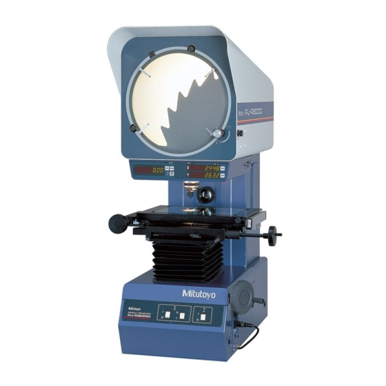
This chapter describes the system outline, and the name and function of each part on the PJ-A3000 series Measuring Projector. 1.1 Outline The Mitutoyo PJ-A3000 series Measuring Projector is a multi-purpose measuring microscope for factory inspection use. It can perform precision measurement of workpiece dimensions, contours and surface features. -
Page 13: Control Panel
[1] Projector head [2] Projection screen [3] Screen rotating knob [4] Screen clamp knob [5] Angle counter [6] XY counter [7] Projection lens [8] Reflected illuminator, Condenser lens for reflected illuminator Cross-travel stage [10] Control panel Contour illuminator (interior) [11] [12] Focusing wheel [13] Power panel [14] XY counter output connector... -
Page 14: Angle Counter And X, Y Counter
1. Overview 1.1.3 Angle counter and X, Y counter (1) Angle counter (2) X, Y-axis counter [10] [9] [3] [5] [7] [8] (1) Angle counter [1] Angle display unit [2] Zero-set key [3] ABS/INC mode indicator [4] Angle unit selector / offset switch [5] ABS/INC mode selector switch (2) X, Y-axis counter [6] mm/E indicator or inch/mm indicator... -
Page 15: Power Panel
1.1.4 Power panel (Right lateral front part of main unit) [1] Plug socket [2] Fuse holder [3] Voltage selector [4] GND terminal [5] Power switch 1 - 4 No.99MBA043A... -
Page 16: Installation And Setup
The PJ-A3000 series Measuring Projector consists of high-precision parts, including guide faces, linear scale units, and optical unit, that must be kept free of dust and dirt. Use and store the PJ-A3000 series Measuring Projector in a place where it will not be subjected to dust and dirt. -
Page 17: Transportation And Installation
2.1.2 Transportation and installation Be sure to use the supplied carrying handles when handling, shifting or installing the projector and due to its heavy weight (for PJ-A3010F-200, about 120kg) four people are required to carry it. The PJ-A3000 series has been fully adjusted at the plant, therefore take special care when handling and setting up the projector so that no part of the projector is subjected to impact or vibration. -
Page 18: Setting Up The Main Unit
2. Installation and Setup 2.1.3 Setting up the main unit The projector must be set up on the optional stand or a rigid, stable mount. Use the leveling bolts on the projector base to compensate for any inclination. Leveling bolts Carrying handles 2.1.4 Removing the carrying handles After setup, remove the carrying handles and cover the screw holes with the supplied hole... -
Page 19: Assembly
2.2 Assembly 2.2.1 Installing the cross-travel stage and Digimatic Head (for PJ-A3005D-50) Turn the focusing wheel clockwise to lower the cross-travel stage mount down to the end of its displacement. Focusing wheel Gently place the cross-travel stage on the mount. Slide the moving sections to the left and right to check the screw hole positions, then use the four hex-socket head screws (supplied in the standard accessory box) to temporarily fix the cross-travel stage in place. - Page 20 2. Installation and Setup 3. Installing the Digimatic Head Loosen the clamp screw and hex-socket head screw on the bracket. Slowly insert the stem of the Digimatic Head into the bracket as far as it can go, then secure it in place with the hex-socket head screw. Do not fasten the screw too tight, otherwise the spindle of the Digimatic Head will not move smoothly.
- Page 21 4. Connecting the Digimatic Head cables (for PJ-A3005D-50) Remove the dust-prevention cap from the output connector on a side of the Digimatic Head. Connect the cable for the counter to the output connector. Output connector Confirm sufficiently to connect so that the connection of X-axis and Y-axis may be not NOTE wrong.
-
Page 22: Installing The Cross-Travel Stage And Connecting The Linear Scale Cables (Pj-A3010F-200)
2. Installation and Setup 2.2.2 Installing the cross-travel stage and connecting the Linear Scale cables (for PJ-A3010F-200) 1. Remove the cable outlet cover. X-axis Y-axis Cable outlet cover Gently place the cross travel stage on the cross travel stage mount. Slide the moving parts to the left and right to align the screw holes, then use the four hex-socket head screws supplied to temporarily fix the cross travel stage in place. - Page 23 Place the linear encoder connector into the projector. Connect the signal cables from the circuit board in the projector to the connector. Attach the cable outlet cover. Connector for Linear encoder The cross-travel stage should be secured when the adjustment of its travel direction is complete. (Refer to “2.5.2 Aligning the cross-travel stage travel direction to the cross-hair lines”.) 2 - 8 No.99MBA043A...
-
Page 24: Connecting The Optoeye A2 Image Edge Sensor• I For Pj-3010F-200• J
2. Installation and Setup 2.2.3 Connecting the Optoeye A2 Image Edge Sensor for PJ-3010F-200 1. Remove the cable outlet cover. 2. Disconnect the linear encoder connectors from the P.C.B inside the Profile Projector. 3. Attach the cable outlet cover. 4. Connect the linear encoder connectors to the Optoeye A2 Counter. Connector for Linear encoder Optoeye A2 Counter... -
Page 25: Mounting The Projection Lens
2.2.4 Mounting the projection lens Remove the lens mount cap and the projection lens cap. Hold the lens so that the red index dot of the projection lens faces you. Align the index dot of the projection lens with that of the lens mount, push the projection lens upwards, then rotate the lens clockwise approximately 60°... -
Page 26: Connecting The Power Cord
2. Installation and Setup 2.2.6 Connecting the power cord Turn off the main switch. Connect the power cord to the power panel and plug it into the power outlet. Main switch Plug socket Power cord Use the power cord supplied with the projector. Use the GND terminal for grounding. -
Page 27: Initial Checks (Functional Check)
2.3 Initial Checks (Functional Check) Each projector is factory-inspected and adjusted, and has been safeguarded at all stages of shipment and transport, but prior to first time use, perform the following checks. NOTE While checking cables, make sure that all switches are tuned OFF. 2.3.1 Electrical component connectors Make sure that the power cord, plug socket, voltage selector, power switch, and GND terminal are securely connected. -
Page 28: Cross-Travel Stage
2. Installation and Setup 2.3.5 Cross-travel stage Is the stage glass clean and free of scratches? • Move the stage by hand over its full range. Does it move smoothly? • Is there any play or noise? • (Use the Micrometer Head to move the cross-travel stage and check the above points.) 2.3.6 Projection screen Is the screen glass clean and free of scratches? -
Page 29: Initial Checks (Performance Check)
2.4 Initial Checks (Performance Check) 2.4.1 Checking the position of the contour illumination bulb filament Carefully remove the projection lens. Turn on the power switch and contour illumination switch to project the filament of the contour illumination bulb on the screen. Confirm that the filament image is projected in the approximate center of the screen. - Page 30 2. Installation and Setup Frame of the reflected illumination condenser lens Clamp knob For the vertical position adjustment of reflected illuminator, loosen the clamp knob to adjust with the • clamp knob or the frame of reflected illumination condenser lens. 2 - 15 No.99MBA043A...
-
Page 31: Projection With Contour Illumination
2.4.3 Projection with contour illumination 1. Turn on the contour illumination bulb. ( Use the brightness selector switch (HIGH and LOW) to select the light intensity. ) The workpiece profile is projected on the screen. Projection screen Workpiece profile 2 - 16 No.99MBA043A... -
Page 32: Projection With Reflected Illumination
2. Installation and Setup 2.4.4 Projection with reflected illumination 1. Turn on the reflected illumination bulb. 2. The image of the workpiece surface is projected on the screen. 3. Mount the half-reflecting mirror at the top of the projection lens frame so that the mirror is aimed towards the surface illuminator, as shown below. -
Page 33: Color Fitter
2.4.5 Color fitter This filter reduces eye fatigue. See the following for the insertion method. Color fitter Main unit left side 2 - 18 No.99MBA043A... -
Page 34: Checking The Magnification Accuracy
2. Installation and Setup 2.4.6 Checking the magnification accuracy 1. Mount the projection lens. ( Refer to “ 2.2.4 Mounting the projection lens ”) 2. Place a standard scale (optional accessory, No. 172-116) on the cross-travel stage to project its image on the screen. 3. - Page 35 The magnification error is specified as ± 0.1% or less for contour illumination, and the tolerance for each measured point is tabulated below. (If the magnification error for contour illumination falls within the tolerance, that for reflected illumination will also fall within the specified tolerance of ±...
-
Page 36: Checking The Cross-Travel Stage Travel Direction
2. Installation and Setup 2.4.7 Checking the cross-travel stage travel direction 1. Mount the least magnified projection lens. 2. Place a reference piece on the stage to project its image on the screen. Reference piece Stage glass Cross-travel stage 3. Set the protractor screen reference line to "0". “0”... - Page 37 4. Move the cross-travel stage along the Y-axis (back and forth), and align the edge of the reference piece with the horizontal cross-hair line. 5. Move the cross-travel stage along the X-axis (left and right), and confirm that the edge of the reference piece is aligned with the horizontal cross-hair line over the entire length of stage X-axis travel.
-
Page 38: Checking The Cross-Travel Stage Feed Error
X-axis (left-right) and Y-axis (front-rear). 4. Check the feed error in the opposite travel directions (i.e. returning directions) for both X- and Y-axes. Contact Mitutoyo if the error is excessive. • 2.4.9 Checking the resolution (in contour illumination mode) 1 . -
Page 39: Adjustment
Reference piece Projection screen 2. When the adjustment is complete, tighten the stage mounting screws. Re-check the stage travel direction. 2.5.3 Centering the protractor screen This adjustment is performed by Mitutoyo service personal. • 2 - 24 No.99MBA043A... -
Page 40: Operation
Operation This chapter explains the setup for measurement including the optical system installation and workpiece set-up. 3.1 Projection Lens Selection 3.1.1 Selecting the projection lens Select the appropriate projection lens magnification according to the required field of view, measuring method and accuracy requirements. (Refer to “6. Specifications”.) 100X Built-in Half-reflecting mirror... -
Page 41: Replacing The Projection Lens
3.1.2 Replacing the projection lens This projector has adopted the fixed focus lens to 10X to 100X. When replacing the projection lens in order to change the magnification, it is required to switch the condenser lens according to the magnification of projection lens. 3.2 Mounting the Workpiece Mount a workpiece on the stage glass or use a fixture or a jig to hold it in position. - Page 42 3. Operation For cylindrical workpieces : V-block and clamp (No. 172-378) • For light-weight, flat workpieces which are difficult to fix : Clamp (No.176-107) • Workpiece Clamp V-block and clamp Workpiece Stage glass Stage glass Cross-travel stage T-groove T-groove Cross-travel stage For screws or cylindrical workpieces with center holes : Swivel center support •...
-
Page 43: Focusing And Positioning The Workpiece
3.3 Focusing and Positioning the Workpiece 3.3.1 Focusing Bring the workpiece into focus by rotating the focusing wheel to move the cross-travel stage up and down. Projection lens Focusing wheel Be careful not to bump the Projection lens against a workpiece or fixture during NOTE focusing. -
Page 44: Positioning The Workpiece
3. Operation 3.3.2 Positioning the workpiece When the image is in focus on the screen, align the measured edge of the workpiece to the measuring axis of the cross-travel stage. Move the workpiece or the fixture so as to align the workpiece image with the cross-hair lines on the screen. Rotary table (No.176-106, 172-196) is suitable for performing alignment. -
Page 45: Measurement And Inspection
3.4 Measurement and Inspection The measuring method for each application should be determined by the measurement factors involved : shape, size and quantity of workpieces, purpose, required accuracy, etc. The following methods are basic examples and can be developed further depending on the particular requirement. - Page 46 3. Operation Operation • Operation When using the X, Y counter (PJ-A3005D, PJ-A3005F, PJ-3010F) Move the stage so that one end of the workpiece is aligned with the cross-hair. Press the zero button of the X-axis to set the counter to zero. Zero setting Move the stage so as to align the other end of the...
- Page 47 • X, Y-axis counter (PJ-A3005D-50, PJ-A3010F-100, PJ-A3005F-150, PJ-A3010F-200) X, Y-axis counter mm/E indicator or inch/mm indicator The LED for the active unit is lit. Resolution X-axis counter PJ-A3005D 0.001 mm PJ-A3005F PJ-A3010F Resolution Y-axis counter PJ-A3005D 0.001 mm PJ-A3005F 0.001 mm PJ-A3010F 0.001 mm Sets the X-axis counter to zero at any X-axis...
-
Page 48: About Parameters
3. Operation 3.4.2 About parameters To actually perform measurement, it is necessary to set up the count direction (count-up or count-down direction), resolution, etc. Also, if setting compensation constants for measuring errors generated according to mechanical operation and various conditions, you can make a measurement more easily and correctly. - Page 49 RS-232C output format setup 1 : MPK-9/7/5 specification (Sets RS-232C data to the output format 2 : Special use of Mitutoyo data processing unit MPK-9/7/5) For the projectors of the type using Digimatic Head, pay attention to next points. NOTE Use as one time of sampling, because No.
- Page 50 3. Operation Parameter setting procedure X-axis display unit Y-axis display unit Q-axis Parameter Button Q-axis display Operating procedure setup operation example Starting the Hold down the “MODE” and MODE parameter “ABS/INC” buttons at a time setup mode more than 3 seconds. ABS/INC F1 →...
- Page 51 3.Rotate the screen glass so that the rotation knob and the display of angle counter is counted in the plus direction. Revolve the screen glass to adjust the cross hairs of screen glass with the index once again. 4.The angle counter is corrected, when the display unit switching key and the angle display zero-set key are pressed in the condition of step 3 simultaneously.
- Page 52 3. Operation Parameter Button Counter display Operating procedure setup operation example Setting the 1.Press the “MODE” button to MODE display unit select parameter [F1]. ZERO (Selecting mm) 2.Press the “ZERO” button to select [mm]. Setting the 1.Press the “MODE” button to MODE count direction select parameter [F2.1].
- Page 53 Parameter Button Counter display Operating procedure setup operation example Setting the 1.Press the “MODE” button to MODE RS-232C select parameter [F7.1]. ZERO communication 2.Press the “ZERO” button to condition(Selectin select [96]. g a baud rate of 9600bps) Setting the 1.Press the “MODE” button to MODE RS-232C select parameter [F7.2].
-
Page 54: Dimensional Measurement Using A Scale
3. Operation 3.4.3 Dimensional measurement using a scale Place the scale on the screen and measure the enlarged image. Divide the measurements by the magnification of the projection lens to determine the actual dimensions. Magnified dimension Projection screen Workpiece Scale [Example] Measured value on the screen: 150mm Projection lens magnification: 10X... -
Page 55: Angle Measurement (Using The Angle Counter)
3.4.5 Angle measurement (Using the Angle counter) Using the protractor screen and the rotary table for measuring angles: Loosen the clamp knob and use the rotation knob to turn the protractor screen. • • g 0” line Screen rotation knob Clamp knob NOTE Always use the rotation knob to rotate the protractor screen. - Page 56 3. Operation Angle counter [1] Angle display Range : ± 360 ° ( ± 370 ° in ABS mode) Resolution : 1' (or 0.01 ° ) [2] Zero-set key Sets the angle counter to zero at any position desired. ABC mode : Hold down the key for about 3 seconds. INC mode : Press then release the key.
- Page 57 Measuring in ABS mode • ( Angle counter setting : 1' ) Step Procedure Screen Counter Display Align the vertrex of the angle to be measured with the intersection of the cross-hair lines, then rotate the protractor screen to align one edge of the angle with a cross-hair line.
- Page 58 3. Operation Measuring in ABS/INC mode • ( Angle counter setting : 1' ) Step Procedure Screen Counter Display Align a cross-hair line on the screen with the datum. Set the angle counter to ABS to mode, then set it to zero. 3 sec.
- Page 59 Step Procedure Screen Counter Display Rotate the protractor screen to measure θ c. Measure θ ( θ is displayed when switching to the ABS mode. ) 3 - 20 No.99MBA043A...
- Page 60 3. Operation (2) Using the protractor screen and the rotary table for measuring angles: The cross travel of the stage is normally used in conjunction with the rotary movement of the table for measuring angles, because it is difficult to align the center of the rotary table with the vertex of the measured angle.
- Page 61 MEMO 3 - 22 No.99MBA043A...
-
Page 62: Troubleshooting
Troubleshooting 4.1 Main Unit Symptom Check point Remedy Is the power cord securely Connect the power cord The fan motor connected? securely. does not operate, Is the power supply voltage Adjust the power supply even if the power consistent with the rated voltage? voltage to the rated voltage. -
Page 63: Counter Unit
Scale is found to be damaged, operates correctly and the Y-axis contact your dealer or the counter dose not, swap the X-and nearest Mitutoyo sales office. Y-axis Linear Scale connections. • If the same problem persists on the same counter (i.e. X-axis counter... -
Page 64: Error Messages And Remedies
When an error code has been cleared (power is turned on), the counter displays all zeros. Perform measurement from the start. If there is play or abnormal noise present, contact Mitutoyo. Do not disassemble the unit or unit or force the wheel. -
Page 65: Abnormal Protractor Screen Operation
4.4.3 Abnormal protractor screen operation. If the screen rotation, fine adjustment, or clamp dose not work normally, contact Mitutoyo. Do not force them. 4.4.4 Partial obscured image. Check the following points. Contact Mitutoyo when required depending on the problem: (1) Is the projection lens properly mounted? -
Page 66: Maintenance
Maintenance This chapter explains the daily maintenance that must be performed on the Measuring Projector PJ-A3000 series, including cleaning and the replacement of consumable parts. 5.1 Maintenance of Optical Components 5.1.1 Projection lens Compared with ordinary hard glass, the optical glass of the projection lens used for the projector is soft and subject to scratches. -
Page 67: Maintenance Of Mechanical Components
5.2 Maintenance of Mechanical Components 5.2.1 Projector main unit Periodically lubricate the feed screws and gears for the cross-travel stage vertical travel. To do so, open the door at the right front of the projector, and apply a thin coat of grease using a brush. -
Page 68: Replacing Disposable Parts
5. Maintenance 5.3. Replacing Disposable Parts 5.3.1 Bulbs for contour and surface illuminators To prevent personal injury, do not touch a hot bulb during use or immediately after tuning it off. To prevent the bulb from being stained with oil or fingerprints, do not touch the bulb with your hand. - Page 69 Each two bulbs can be mounted to each illuminator after opening the doors for contour NOTE and reflected illumination. Slide the bulb adapter plate to the click position, when the one of the two's bulb is blown. Tilt each illumination bulb selection switch to the rear side, when the bulb A is lit.
-
Page 70: Fuse
5. Maintenance (6) To mount the bulb, insert it straight into the socket as far as it can go so that the bulb filament image is centered in the convex mirror. (7) To mount the bulb, insert it straight into the socket as far as it can go so that the bulb filament image is centered in the convex mirror. -
Page 71: Stage Glass
5.3.3 Stage glass While pushing the stage glass toward the projector rear, lift the front part of the glass to remove it. (For PJ-3005D, remove the glass fixing screw. ) Stage glass Cross-travel stage Mount the new stage glass The X-Y stage glass is held in place by a leaf spring. Be careful not to lose this spring. CUTION 5.4 Periodic Inspection To ensure a long working life of the projector, perform periodic inspection, cleaning and... -
Page 72: List Of Consumable
5. Maintenance 5.5 List of Consumable Order No. Part name Remark 512305 Halogen bulb 24V-150W (Life : 500 hours) 515530 Halogen bulb 24V-150W (Life : 50 hours) 384211 Tube fuse BS SEMKO S506 5A (for 200V-system region ) 12BAE152 51MS080H 8A (for 1 00V-system region ) φ... - Page 73 MEMO 5 - 8 No.99MBA043A...
-
Page 74: Specifications
Specifications 6.1 General 6.1.1 Common specifications Protractor screen Effective measurement diameter: φ315mm (12.4") Angle display: Digital Measuring range: ±360° Projection lens 10X (Standard accessory) 20X, 50X, 100X (Optional accessory) Illumination unit Contour illumination : Telecentric illumination with 2-stage intensity selector, Halogen bulb(built-in): 24V 150W, Average life 500 hours Reflected illumination : Vertical and oblique surface illumination, Halogen bulb(built-in): 24V 150W, Average... - Page 75 Environmental conditions Temperature(in operation) : 0 to 40°C Humidity(in operation) : 20 to 80% Dust : The same conditions as for measurement rooms Dimensions W X D X H : 400 X 742 X 1093mm (15.75 X 29.21 X 43.03”) Screen center height : 854mm (33.62”) 6 - 2 No.99MBA043A...
-
Page 76: Individual Specifications
6. Specifications 6.1.2 Individual specifications 302-711 302-712 302-713 302-714 302-718 302-719 Order inch/ mm mm/E 302-701 302-702 302-703 302-704 302-705 302-706 302-707 302-708 302-709 302-700 -A3010F -A3005F -A3010F -A3005D -A3010F -A3005F -A3010F -A3005D -A3005R Model No. -A3000 -200 -150... -
Page 77: Date Output• I Rs232C• J
6.1.3 Date output (RS232C) For the projector equipped with the RS232C port, the measured date of the counter unit is output via the serial output connector to a peripheral, such as two-dimensional data processing unit Micropak 9/7 or QM-DATA or two-dimensional data processing program 2Dpak or QSPAK. Communication Specifications Transmission method: Half duplex Transmission control: Asynchronous (Start-stop transmission) - Page 78 6. Specifications Example of cable that can be used The following illustrates two types of reference cables which are used to connect the counter to a DOS/V PC. One of the cables does not use control lines and other uses control lines. Cable 1 (Control lines are not used) Pin No.
-
Page 79: Data Output Operation
6.1.5 Data output operation A displayed value on the counter unit can be output by inputting an external load signal or commands from a peripheral, such as a personal computer. Data output A) For the external load signal Only the data on the axis on which the external load box switch is pressed is output to a peripheral. - Page 80 6. Specifications 2) Multi-axes counter output A coordinate data of each axis is the same as the output format of a single-axis counter. For one-axis ) Q-axis data CR LF For two-axes ) X-axis data Y-axis data CR LF For three-axes ) X-axis data Y-axis data Q-axis data CR LF...
- Page 81 4) Error Next error code is output, when the error arises in the counter. RS232C error code Display Error cause Remedy (method of return) Parity error Press the X-axis zero-set CR LF arising button. Transmit C0 (zero) command Over-run error CR LF from the peripheral equipment arising...
-
Page 82: Connecting Micropak
6. Specifications 6.1.6 Connecting Micropak It is necessary to perform the Micropak 9 / 7 / 5 setting when connecting the Micropak to the counter unit. For information about setting up Micropak 9 / 7 / 5, refer to the Micropak user’s manual. Connection Order No.937998 Counter unit... -
Page 83: Connecting Qm-Data 200
While the projector may be used on a stand alone basis, it also has the capability of transmitting data to external devices through the counter. Incorporating the projector into the M-SPC(Mitutoyo Statistical Process Control) system permits measurements from the projector to be statistically analyzed in order to create histograms and process control charts, etc. - Page 84 6. Specifications Output circuitry : Input circuitry : DATA TYPE A TYPE A SIGNAL INPUTTO to GAGE (OPEN-COLLECTOR) SIGNAL INPUTTO C-MOS IC from GAGE INPUT =22kΩ ±10% +30% =330ph NPN TYPE transistor 2SC2855 (or equivalent) -20% or TTLIC(WITH OPEN-COLLECTOR TYPE) =1S1588 (or equivalent) DATA Counter...
- Page 85 (2) Output data format Each measurement is transmitted as 13-digit serial data. Each digit consists of a 4-bit data that represents 0 to F(hexadecimal). Output is sequential starting with the LSB(least significant bit). The table on the right shows the assignments of the 13 digits. Example of output data d5 d6~d11 d12 d13 mm →...
- Page 86 6. Specifications (3) Timing chart DATA 10ms ≤ t ≤ 2s 150 µ s ≤ t ≤ 200 µ s 150 µ s ≤ t ≤ 400 µ s 150 µ s ≤ t ≤ 400 µ s (4) DP-1 printing example Referring to DP1-DX, the printing example is shown as follows.
-
Page 87: Performance Table For The Pj-A3000 Series Projectors
6.2 Performance Table for the PJ-A3000 Series Projectors (Unit : mm) Contour illumination Reflected illumination 100X 100X Magnification 31.5 15.7 31.5 15.7 Field of view Working 32.5 12.6 12.6 distance 123.5 123.5 123.5 123.5 123.5 123.5 123.5 123.5 PJ-A3000 123.5 123.5 123.5 123.5... -
Page 88: Optical Path
6. Specifications 6.3 Optical Path Second mirror Projection screen Projection lens mounting plane First mirror Filament Heat absorbing filter Filament 6 - 15 No.99MBA043A... -
Page 89: External Dimensions
6.4 External dimensions 6.4.2 Main Unit PJ-A3000 PJ-A3005R-50 6 - 16 No.99MBA043A... - Page 90 6. Specifications PJ-A3005D-50 PJ-A3010F-100 6 - 17 No.99MBA043A...
- Page 91 PJ-A3005F-150 PJ-A3010F-200 6 - 18 No.99MBA043A...
-
Page 92: Cross-Travel Stage
6. Specifications 6.4.2 Cross-travel stage 16-M6,depth10 Traverse range : 200X100 Traverse range : 150X50 Detailed drawing of T-groove Traverse range : 100X100 Detailed drawing of T-groove 6 - 19 No.99MBA043A... - Page 93 Traverse range : 50X50 Detailed drawing of T-groove Fixed stage Detailed drawing of T-groove 6 - 20 No.99MBA043A...
-
Page 94: Accessories
6. Specifications 6.5 Accessories 6.5.1 Standard accessories Model No. PJ-A301 PJ-A300 PJ-A301 PJ-A300 PJ-A300 Quanti PJ-A30 Part Name Order No. --200,-2 -150,-15 -100,-10 -50,-50E Projection lens 10x set • › • › • › • › • › • › 172-202 Shield plate •... -
Page 95: Optional Accessories
6.5.2 Optional accessories Model No. PJ-A3010F PJ-A3005F PJ-A3010F PJ-A3005D -200 -150 -100 Part Name Order No. Quan PJ-A3005R PJ-A3000 tity PJ-A3010F PJ-A3005F PJ-A3010F PJ-A3005D -200E -150E -100E -50E Projection lens 20x set • › • › • › • › •... - Page 96 6. Specifications Model No. PJ-A3010F PJ-A3005F PJ-A3010F PJ-A3005D Part Name -200 -150 -100 Order No. Quanti- PJ-A3005R PJ-A3000 PJ-A3010F PJ-A3005F PJ-A3010F PJ-A3005D -200E -150E -100E -50E Scratch resistance stage • › • › glass (50X50) 12BAE137 Scratch resistance stage 12BAE138 •...
-
Page 97: Part Name
Model No. Quanti- Part Name Order No. PJ-A3010F PJ-A3005F PJ-A3010F PJ-A3005D PJ-A3005 -200 -150 -100 PJ-A3000 PJ-A3010F PJ-A3005F PJ-A3010F PJ-A3005D -200E -150E -100E -50E 512066 Overlay chart 512067 Overlay chart 512069 Overlay chart 512070 Overlay chart 512071 Overlay chart 512072 Overlay chart •...