Table of Contents
Advertisement
Advertisement
Table of Contents

Related Manuals for Scientific Atlanta PowerVu D985


Summary of Contents for Scientific Atlanta PowerVu D985
- Page 1 PowerVu Model D9850 ® Program Receiver Installation and Operation Guide...
- Page 2 Please read this entire guide Veuillez lire entièrement ce guide Bitte das gesamte Handbuch durchlesen Sírvase leer completamente la presente guía Si prega di leggere completamente questa guida Important Please read this entire guide before you install or operate this product. Give particular attention to all safety statements.
- Page 3 PowerVu Model D9850 ® Program Receiver Installation and Operation Guide...
- Page 4 Please read this entire guide Veuillez lire entièrement ce guide Bitte das gesamte Handbuch durchlesen Sírvase leer completamente la presente guía Si prega di leggere completamente questa guida Important Please read this entire guide before you install or operate this product. Give particular attention to all safety statements.
- Page 5 QUICK SETUP – READ ME FIRST! Scientific-Atlanta PowerVu Model D9850 Program Receiver If you want to receive programs using a PowerVu scrambled service, fill in the information below and follow the Step-by-Step instructions. Before you start, fill in the following: Program to receive: Program Provider: Satellite &...
- Page 6 For Free-to-air Service Setup only On the Main Menu, press the right arrow key ( ) so the cursor (♦) is to the left of the Setup menu item. Press the Select button to display the Setup Menu. Then press the right arrow key ( ) again so the cursor (♦) is to the left of the More menu item.
- Page 7 Note that if you require LNB Power for the RF signal input, set Power to either 13, 18 or Polariser. Refer to the Presets Menu section to choose the appropriate setting. At this time, you should get a (signal) Lock. (Check RF, if not). Press MENU, the message Acquiring Network Information should display.
- Page 8 PowerVu D9850 Program Receiver Installation and Operation Guide 4006105 Rev B...
-
Page 9: Safety Precautions
Safety Precautions Protect yourself from electric shock and your system from damage! • This product complies with international safety and design standards. Observe all safety procedures that appear throughout this guide, and the safety symbols that are affixed to this product. •... - Page 10 Alimentation Important! Ce produit fait partie de la classe II. Ce produit se branche dans une prise murale. Cette dernière doit être placée à proximité du produit et doit être facilement accessible. Ne branchez ce produit qu'à la source d'alimentation indiquée sur son panneau arrière. Si ce produit n'a pas d'interrupteur d'alimentation générale, le cordon d'alimentation remplit ce rôle.
-
Page 11: Precauciones De Seguridad
Precauciones de seguridad ¡Protéjase contra la electrocución y proteja su sistema contra los daños! • Este producto cumple con los criterios internacionales de seguridad y diseño. Observe todas los procedimientos de seguridad que aparecen en esta guía, y los símbolos de seguridad adheridos a este producto. -
Page 12: Important Safeguards
Alimentazione Importante! Questo prodotto è protezione Classe II. Questo prodotto si inserisce in una presa di corrente. La presa di corrente deve essere in prossimità del prodotto, e deve essere facilmente accessibile. Collegare questo prodotto solamente alla fonte di alimentazione indicata sul pannello posteriore di questo prodotto. - Page 13 Accessories: Do not place this product on an unstable cart, stand, bracket, or table. The product may fall causing serious injury to a child or adult, and serious damage to the product. Use only with a cart, stand, bracket, or table recommended by Scientific-Atlanta. Any mounting of the product should follow the instructions, and should use a mounting accessory recommended by Scientific-Atlanta.
- Page 14 Overloading: Do not overload wall outlets, extension cords or integral convenience receptacles, as this can result in a risk of fire or electric shock. Object and Liquid Entry: Never push objects of any kind into this product through openings as they may touch dangerous voltage points or short-out parts that could result in a fire or electric shock.
- Page 15 Important Notice for Customers in the United Kingdom Class II Apparatus Using a Two-Wire Power Cord Important! The wires in this mains lead are coloured in accordance with the following code: Colour Mains lead wire Blue Neutral Brown Live As the colour of the wires in the mains lead of this apparatus may not correspond with coloured markings identifying the terminal in your apparatus, proceed as follows: IF wire colour is Connect it to…...
-
Page 16: Warranty And Disclaimer
Warranty and Disclaimer Statement Scientific-Atlanta warrants good title to any hardware furnished by it. For software, we warrant that we have the right to grant any software license granted. We warrant during the Warranty Period as defined below that services will be performed in a good and workmanlike manner. We also warrant that during the Warranty Period, each item we deliver (other than separately licensed software and services) (an “Item”) will be free from material defects in workmanship and materials and under ordinary use, conform in all material respects to its published specifications current at the time the... -
Page 17: Table Of Contents
Table of Contents Class II Apparatus Using a Two-Wire Power Cord ..........xiii Warranty and Disclaimer ..................xiv Introducing the Receiver ................... 1 Welcome ....................1 Keypad Conventions .................. 2 Installing the Receiver ..................5 Unpacking and Inspection ................. 5 Rear Panel Connections ................ - Page 18 PowerVu D9850 Program Receiver Installation and Operation Guide 4006105 Rev B...
-
Page 19: Introducing The Receiver
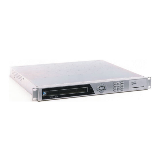
Introducing the Receiver Welcome ® Welcome to Scientific-Atlanta’s PowerVu Model D9850 Program Receiver. This receiver is designed for content distribution applications requiring 4:2:0 video decoding and offers features such as the capability to receive digitally-encrypted video, audio, utility data, IP data, and VBI. Composite video and balanced audio outputs can be connected to analog modulators for analog cable distribution. -
Page 20: Keypad Conventions
• IP data • SNMP control • Web browser access Optional Features • 4-RF L-band inputs • DVB-ASI transport input • AES-3id digital audio outputs • SDI video with embedded audio outputs • IP data output (up to 50 Mbps) Keypad Conventions Throughout this guide, there are references to parts of a keypad on the front of the receiver. - Page 21 Introducing the Receiver INFO button Press the button on the lower left of the numeric keypad for context-sensitive help messages*. MENU button Press the button on the lower right of the numeric keypad*. This button functions as the Escape key, backing the user out of menus and data entry fields.
- Page 22 When this symbol appears on the right-hand side of the LCD screen, the UP arrow key is active. DOWN* When this symbol appears on the right-hand side of the LCD screen, the DOWN arrow key is active. Download In Progress (DL) This symbol, when displayed, indicates that the receiver is currently downloading a software update and storing it into memory in the background...
-
Page 23: Installing The Receiver
Installing the Receiver Unpacking and Inspection When removing the receiver’s protective packaging, inspect the shipping carton for damage. If any signs of damage are evident, notify the carrier immediately before accepting the consignment. Contact your local Scientific-Atlanta representative if any signs of damage or defects are discovered. Retain the packaging in the event of return, or for equipment storage. -
Page 24: Rear Panel Connections
Rear Panel Connections ® Model D9850 Program Receiver - 4 RF Unit R F1 L N B P W R ASI IN + 1 3 / + 1 8 V 4 0 0 m A M A X BALANCED BALANCED TONE AUDIO 1 AUDIO 2... -
Page 25: Installing The Unit
Operating the Decoder Installing the Unit Installation of the receiver requires mounting the unit into a rack assembly and connecting signal and power cables to the rear panel. Installing the Rack Assembly The receiver is one standard rack unit (1RU) high and should be mounted in a standard 19-inch wide by 24-inch deep rack space. - Page 26 Connect the power cord (supplied with the unit) between the rear panel power receptacle and a 100V to 240V, 50/60 Hz ac power outlet. CAUTION! This Product must be Equipotentially Earthed for Equipment Protection and EMC. Use Earth Connection Indicated by Item 10 on the Rear Panel Draw- ing.
-
Page 27: Operating The Receiver
Operating the Receiver This chapter shows how to use the function menus accessed on the front panel of the receiver and the impact of such operations. Front Panel Front Panel Controls and Indicators The receiver is operated using controls and indicators on the front panel. These include the numeric keypad, the Navigation/Selection keypad, the LCD, the ALARM and SIGNAL indicators, as well as the Card Reader. -
Page 28: General Operation
may be status data or identifier information. It can also display optional functions available for tuning operations. The bottom line will show selections or parameter values available using the navigation/selection keypad. The items are selected by pressing the SELECT button (center button) on the navigation/selection keypad. Navigation/Selection Keypad The navigation buttons (LEFT, RIGHT, UP and DOWN) and the SELECT button on this keypad are the primary controllers. -
Page 29: Menu Structure Overview
Operating the Receiver Menu Structure Overview Main Menu Status Menus Diagnostic Menus Preset/Input Menus About Menus Setup Menu More Features Menu Decode Menu Admin Menus PSI Menus A/V Menus Subtitles Menus IP Setup Menus TxOut Menu Cueing Menus Main Menu Operation of the receiver begins at the Main menu. -
Page 30: Status Menu
Status Menu This menu is used to see the status of various elements of the receiver. These fields are display only. SELECT moves Prog Status Type the cursor to the line below AUTH 5011 (activation indicated by square brackets) for data entry. SELECT activates this field (activation indicated by angle brackets). - Page 31 Operating the Receiver L-Band – Shows the current L-Band frequency (MHz). Freq – Shows the current downlink frequency (GHz). Lock – Shows the current signal lock status. Lvl – Shows the current signal level. AFC – Shows the current Automatic Frequency Control count. SymRate –...
-
Page 32: Presets Menu
Alarms and Warnings Menus These menus allow you to see all of the current alarms and warnings. System Alarms Menu – This menu shows all Alarm messages since the last time they were cleared or the receiver was power cycled. The user can scroll through the messages by pressing Select and then using the UP and DOWN arrow keys. - Page 33 Operating the Receiver The following two menus allow you to configure elements of the presets for use with your receiver. P# Freq(GHz) SymRate FEC L-Band 3.449 28.3465 AUTO 1500.0 P# InputIQ NetID Polarization Input AUTO RF 1 P# – This is the preset number (in the range from 1-64) the following settings will be applied to.
- Page 34 Possible settings are H (Horizontal), or V (Vertical). Note that the Polarization cannot be changed when the input is ASI. RF# LO1(GHz) LO2(GHz) Xover(GHz) 9.75 RF# Satellite OrbPos Polar Galaxy 5 125.0 W RF# Power LOSelect(22 kHz) Input – This setting determines the input to use when this preset is selected. Note that the selected Input type must match the input signal connection made on the rear panel.
- Page 35 Operating the Receiver Satellite - This is the name of the satellite currently selected. Choose the satellite you want to use to receive the signal from the list of satellites available. When you select a satellite, the orbital position (OrbPos) is displayed. This is important for automatic switching from one RF input to another in the event of loss of the signal, allowing the receiver to acquire an alternate signal.
-
Page 36: Setup Menus
Setup Menus The Setup Menus are the starting point for all receiver configurations. Use the LEFT and RIGHT arrow keys to select the area of the receiver's operation you would like to setup/configure, and then press SELECT. Setup Menu Admin TxOut Cueing More... - Page 37 Operating the Receiver Changing the Lock Level To change the lock level, the user enters the Admin Setup menu and presses Select with the cursor on the Lock Level option. The option name will change to Enter Lock Level and the cursor will move down into the data entry area. The user can now use the up/down arrows to toggle through the possible lock levels.
- Page 38 Reject – This is the rejected table count. Tables are rejected whenever validation fails due to things like CRC failure or incorrect code or receiver type. Abort – Selecting this option stops a download that is currently being received. Restart – Selecting this option restarts a previously aborted download. Note that the download does not resume from where it was aborted, but restarts from the beginning.
- Page 39 Operating the Receiver Stream – This is the format of the incoming stream. This value is read-only. Output Format – This is the signal format output from the receiver. This value is determined by the Video Format setting and the actual format of the incoming stream.
- Page 40 Stream TV A/R Conversion Act Conv Description Image 4:3 P/B None Conversion is not possible. Normal picture. 14:9 None Conversion is not possible. Normal picture. 16:9 F/W None Conversion is not possible. Normal picture. 16:9 None None Picture is short & fat. 4:3 Stretch 16:9 Auto...
- Page 41 Operating the Receiver Stream TV A/R Conversion Act Conv Description Image 16:9 16:9 14:9 None Conversion is not possible. Normal picture. 16:9 16:9 16:9 F/W None Conversion is not possible. Normal picture. 16:9 None None Picture appears tall and thin. 16:9 Compressed 16:9 4:3 L/B...
- Page 42 WSS Mode - This is the Wide Screen Signalling output mode. It is used to select how the receiver affects PAL WSS when it is present in the VBI. Possible options are Auto, Suppress and Passthrough. The table below describes each of the options.
- Page 43 Operating the Receiver Left – This is the volume adjustment for the Left audio channel, in the range of - 6.0 dB to +6.0 dB. Any value can be entered with the numeric keypad (in the appropriate range), but the UP and DOWN arrows will make increments/ decrements at 0.5 dB steps.
- Page 44 TxOut Menu The TxOut Menu allows you to configure filtering for the MPEG Transport (ASI) output signal. Filter Mode No Output ASI Out Rate User Rate Actual Rate Automatic 68.5 Filter Mode – This is the type of filtering, if any, which occurs on the transport output.
- Page 45 Operating the Receiver ASI Out Rate - This sets the ASI output bit rate (in Mbps) when the unit has an RF input signal. Possible options are Automatic, Minimum and User Selected. The table below describes the affect each of the settings has on the ASI output bit rate. ASI Out Rate Description Selection...
- Page 46 Filter Mode ASI Out Rate Input Source Setting Actual ASI Output Actual ASI Output Bitrate Bitrate No Output Zero Zero Passthrough Same as input source Same as input source Service Channel Scrambled Calculated based on User Rate modulation settings Service Channel Descrambled Calculated based on User Rate Automatic...
- Page 47 Operating the Receiver Cueing Menu This menu allows you to control the receiver's cue tone/trigger features. Cueing is used to automate the insertion and synchronization of localized commercial messages into video programming. Cueing Mode Trigger Polarity Cue Trigger Active High While always available, the following two menus are only applicable when Cue Tone has been selected as the Cueing Mode.
- Page 48 Silence (ms) – The is the silence duration between the tones in milliseconds. The default is 40, and the acceptable range of possible values is from 0 to 80. Seq# – This is the tone sequence to use. The receiver supports up to 16 tone sequences.
- Page 49 Operating the Receiver IP Setup This menu is used to configure the IP options of the receiver. Setup Menu ¡ Admin A/V TxOut Cueing IP CA-SW More ¡ IP Address/Mask Gateway 192.131.244.5 192.131.244.254 ¡ MAC Address 00:02:DE:24:8D:9B ¡ Multicast Filter IGMP Mode Filter list ¡...
- Page 50 The following table shows the most commonly used Subnet mask values to enter for a chosen IP address mask, which will depend on the size of your network. Mask Subnet Mask 255.0.0.0 255.255.0.0 255.255.255.0 MAC Address – This is the MAC address of the receiver. This is a read-only value.
- Page 51 Operating the Receiver Unicast Network/Mask – This is where you enter the specified ranges of the Unicast IP Addresses in conjunction with subnet masks. These unicast IP addresses are forwarded to the specified gateway addresses. Select Add and enter any new addresses you require. Conditional Access Session Word (SW) Setup This menu is used to select the Basic Interoperable Scrambling System (BISS) mode.
- Page 52 menu are the most important with regard to your type of network application and the settings determine which search parameters are used to find the signal you want install the receiver to receive. Stream Tuning Mode Input Sel Auto RF Map Services List Mode Allow Deg'd Install Frequency Tuning...
- Page 53 Operating the Receiver Services List Mode – All of the options on this menu allow you to select which tables to use to obtain tuning and channel lists. The values set on this menu ONLY apply when the Stream Tuning Mode is set to Custom. Possible options for this mode are Allow Deg’d Install or Rigorous Install.
- Page 54 Subtitles Menus This menu allows you to configure what type of subtitling (i.e., DVB or Imitext) is displayed by the receiver, and how the receiver displays subtitling on the TV system. ¡ Op Mode Select Language By Language List ¡ Language List PMT Order Entry...
- Page 55 Operating the Receiver Select Language By Option Description Each subtitling PID can contain multiple languages. Use this setting to select the language from the Language List by toggling Language List through the available selections. If Language List is selected, PMT Order and Entry fields are not used.
-
Page 56: About Menu
About Menu The User Address (UA) is required in order to request program authorization from the uplink. This menu shows basic software version and hardware information useful when requesting customer support from Scientific-Atlanta. Product ID: D9850 Tracking ID: 250102000147 Boot App Safe App Current App 1.01... -
Page 57: Diagnostics Menu
Operating the Receiver Board – This is the Board type and revision. FPGA – This is the Field Programmable Gate Array (FPGA) type and version number. CPLD – This is the Complex Programmable Logic Device (CPLD) version number. PIC Version – This is the Programmable Interrupt Controller (PIC) version number. - Page 58 Alarms/Warnings Menu The first two menus in this branch display the current Alarms and Warnings, respectively. You can scroll through multiple Alarms/Warnings by pressing select and using the UP and DOWN arrow keys. ¡ ¡ No Active System Alarms to Report No Active System Warnings to Report ¡...
- Page 59 Operating the Receiver PSI Menu FreqPlan Sub-Menu This is the Frequency Plan sub-menu. You cannot make any changes here, but you can view the available frequency plans stored in the receiver. The following is a list of the expanded abbreviations: TxID –...
- Page 60 Disaster Recovery Menu This menu allows you to view the mode of operation of the receiver in the event of transmission failure (i.e., loss of signal lock by the receiver). This could be caused by transponder failure, satellite failure, uplink failure, downlink failure, etc.
- Page 61 Operating the Receiver View Parameters Sub-Menu This is the Backup sub-menu. You cannot make any changes here, but you can view the available Backup Set for the Primary or Stand-in Backup Sets downloaded from the uplink. ¡ Backup Set More ¡...
- Page 62 ISI - Installed Signal Input. This is one of the activated presets. When all else fails, the receiver will attempt to tune to the signal it was originally installed to receive. SvID - Service ID. This is last known verified channel. Polar –...
- Page 63 Operating the Receiver Status Sub-Menu This sub-menu indicates the current status of the disaster recovery. You cannot make any changes here, but you can view the status of the disaster recovery. The following is a list of the messages that can be displayed and their descriptions. Messages Description Disaster Recovery Available...
-
Page 64: Snmp Control
SNMP Control The receiver can be controlled via a PC using the Ethernet port. You can either purchase a ROSA Network Management System and interface drivers, or obtain a MIB (Management Information Base) specification to create a PowerVu D9850 program receiver control system. The MIB specification can be obtained from your closest Scientific-Atlanta customer support center detailing the features and operating parameters that can be controlled remotely. - Page 65 Operating the Receiver Start up your web browser and enter the receiver IP address similar to that shown on the screen below. On the Network Password screen, enter the User Name and Password as follows: User Name - user (all lowercase letters) Password - USER (all uppercase letters) Select OK 4006105 Rev B PowerVu D9850 Program Receiver Installation and Operation Guide...
- Page 66 The following web page (main menu) displays if the receiver is online. To view/change the receiver’s configuration, click on one of the menus on the left of the web page to display the available submenus. Most of the options and configurable features accessible from the receiver’s front LCD panel are available through this interface, though the grouping and individual menu names may vary.
-
Page 67: Customer Support Information
Customer Support Information Hotlines Scientific-Atlanta provides customers with 24-hour hotline support from anywhere in the world. If you require technical assistance or product training support, or if you have any questions concerning your Scientific-Atlanta product, contact the appropriate Customer Support Center from those listed below. Location Phone NumberPHone... - Page 68 Customer Responsibility When returning equipment, the customer is solely responsible for equipment packaging and transportation costs both to and from the factory. At the customer's request, Scientific-Atlanta will make reasonable efforts to provide warranty service at the customer's premises, provided that the customer pays current field service rates plus direct travel and accommodation expenses.
- Page 69 Customer Support Information • Your name, your business name and full return address • Contact telephone number • RMA number Ship the product prepaid and insured to the Scientific-Atlanta Customer Support Center (or other repair location) as directed. If you are unsure about where to ship the product, contact your local Scientific-Atlanta Customer Support Center, Scientific-Atlanta dealer or distributor.
- Page 70 PowerVu D9850 Program Receiver Installation and Operation Guide 4006105 Rev B...
-
Page 71: Technical Specifications
Technical Specifications Operating Characteristics Function/Item Specification System MPEG-2/DVB CompatibleEN 300 421, EN 300 468 De-Modulation: QPSK FEC: Variable (1/2, 2/3, 3/4, 5/6, 7/8, or AUTO) Tuner Input Level (1 RF Unit):-35 dBm to -65 dBm for 1 to 4.9999 Msym/s (full transponder power) -25 dBm to -65 dBm for 5 to 45 Msym/s Input Level (4 RF Unit):-35 dBm to -65 dBm for 1 to 4.9999 Msym/s (full transponder power) -25 dBm to -65 dBm for 5 to 29.9999 Msym/s... - Page 72 Function/Item Specification Analog Video Output Number of Channels: One (two identical outputs) Video Decompression Type: MPEG-2 4:2:0 NTSC & PAL Composite Video Level: 1.0 Vpp ± 5% Frequency Response: NTSC: 100 Hz - 4.2 MHz <+0.5 dB/- 0.75 dB PAL: 100 Hz - 5.0 MHz <+0.5/-1.25 dB Maximum Video Bit Rate: 15 Mb/s Chroma-luma Delay: ±...
- Page 73 Technical Specifications Function/Item Specification Optional Inputs/Outputs 4 RF inputs ASI Input: DVB-ASI coaxial, up to 68.5 Mb/s SDI Outputs: 2 Interface: SMPTE 259M (270 Mb/s) Format: Embedded audio on serial D1 video AES-3id Outputs: 2 (one per stereo audio channel) Format: PCM Physical Function/Item...
- Page 74 Provide forced air and/or passive air ventilation for the equipment (forced air ventilation forces air flow through the equipment rack, and passive air ventilation assists air movement through the equipment rack). PowerVu D9850 Program Receiver Installation and Operation Guide 4006105 Rev B...
-
Page 75: Lock Levels
Lock Levels Overview Five (5) lock levels (0, 1, 2, 3, and 4) are available for protecting your receiver and its settings against unauthorized use or modification (see the table below for full details). Lock Level 0 lets you make any changes to the current receiver setup. Lock Levels 1 and 2 limit access to settings that do not compromise the video signal. - Page 76 Actions/Functions Lock 0 Lock 1 Lock 2 Lock 3 Lock 4 User Description Read Read Read Read Read Previous Channel Number Channel Up/Down Command Stream Tuning Mode AC3 Compression Mode Left Volume Audio 1/2 Select Right Volume Stereo/Mono Switch Audio Status Info CA Status IP Address/Routing Cueing Relay...
- Page 77 Lock Levels Actions/Functions Lock 0 Lock 1 Lock 2 Lock 3 Lock 4 User Description Read Read Read Read Read Warnings User Address Info Lock Level Control Video Status Info Factory Reset Start Download (Fixed PID) Stop Download Restart Stopped Download Switch Active Application Reboot Decoder Change Lock Level...
- Page 78 PowerVu D9850 Program Receiver Installation and Operation Guide 4006105 Rev B...
-
Page 79: Alarms And Warnings
Alarms and Warnings Overview The following table outlines all possible Alarms, their causes and what steps to take should they occur. Alarm Description Cause Resolution Transport I/O Transport Input Problem HW Issue Clear Alarm, Reset Unit, if problem persists notify customer service BOOT BOOT Failure HW Issue... - Page 80 The following table outlines all possible Warnings, their causes and what steps to take should they occur. Warning Description Cause Resolution Memory Usage Software exceeding designed Software problem Clear Warnings, Reset Unit. If problem memory limitations persists notify customer service. bat Timeout Bouquet Association Table Uplink Not or...
-
Page 81: Factory Presets
Factory Presets Overview The following table shows the factory preset (i.e., default) values for all the parameters that can be changed using the front panel keypad. Menu Submenu Submenu/Parameter Parameter Default Preset/Input Preset Name Freq(GHz) 3.449 SymRate 28.3465 Auto L-Band 1701.0 InputIQ AUTO... - Page 82 Menu Submenu Submenu/Parameter Parameter Default Video Format Auto TV A/R Convert None WSS Mode Auto Caption Mode Auto AC3 Compression RF Mode Left (audio level adjust) 0.0 dB Right (audio level adjust) 0.0 dB Stereo/Mono STEREO Aud1 (Decoder) AUD1 Aud2 (Decoder) AUD2 TxOut Filter Mode...
- Page 83 Factory Presets Menu Submenu Submenu/Parameter Parameter Default Subtitles Op Mode Select Language By Language List Language List eng English PMT Order First Entry Imiitext Postion Standard ForeGnd Auto BackGnd Auto Diagnostics Alarms/ System Alarm Name Loss of Signal Menu Warnings Transport I/O Shutdown SMI Setup...
- Page 84 PowerVu D9850 Program Receiver Installation and Operation Guide 4006105 Rev B...
-
Page 85: Compliance Information
According to the provisions of the Low Voltage Directive 73/23/EEC and the Electromagnetic Compatibility Directive 89/336/EEC amended per Directive 93/68/EEC Toronto, Canada, January 8, 2003 (Issue place and Date) Scientific Atlanta Canada Inc (Media Networks Division) (Company name) 100 Middlefield Road, Scarborough Ontario Canada M1S 4M6 (Company Address) -
Page 86: Fcc Notices
FCC notices This equipment has been tested and found to comply with the limits for a Class B digital device pursuant to Part 15 of the FCC rules. These limits are de-signed to provide reasonable protection against harmful interference when operated in a residential installation. This equipment generates, uses and can radiate radio frequency energy, and if not installed and used in accordance with the instructions supplied in this manual may cause harmful interference to radio communications. - Page 88 Scientific-Atlanta Canada, Inc. www.scientificatlanta.com This document includes various trademarks of Scientific-Atlanta, Inc. Please see the Notices section of this document for a list of the Scientific-Atlanta trademarks used in this document. All other trademarks shown are trademarks of their respective owners. Product and service availability is subject to change without notice.
Need help?
Do you have a question about the PowerVu D985 and is the answer not in the manual?
Questions and answers