
Related Manuals for GE D20MX


Summary of Contents for GE D20MX
- Page 1 Digital Energy D20MX Processor Hardware User’s Manual 994-0140 Version 1.00 Revision 2 General...
-
Page 2: Copyright Notice
GE Digital Energy Copyright Notice © 2012, General Electric Company. All rights reserved. The information contained in this online publication is the exclusive property of General Electric Company, except as otherwise indicated. You may view, copy and print documents and graphics incorporated in this online publication (the “Documents”) subject to the following: (1) the Documents may be used solely for personal, infor-... -
Page 3: Table Of Contents
Safety words and definitions..................9 PRODUCT SUPPORT Search technical support ...................11 Contact customer support ..................11 Product returns......................12 Upgrade your D20MX processor firmware ..............12 BEFORE YOU START Safety precautions ......................13 Warning symbols ............................14 Regulatory compliance information ................14 CE Mark compliance ............................ 14 Export control classification number .................... - Page 4 TABLE OF CONTENTS INSTALLING THE D20 chassis layouts .....................29 Installation steps ......................31 D20MX Retrofitting the D20MX in an existing D20 ..............33 Required tools and materials..................35 Grounding the D20MX ....................36 Unpacking the D20MX ....................36 Package contents ............................36 Connecting the power supply ..................37 CONNECTING TO Cabling overview ......................39...
- Page 5 Updating D20/D200 configurations to use the D20MX firmware definition with ConfigPro......................75 Updating a D20 configuration to use the D20MX firmware definition with ConfigPro 76 Updating a D200 configuration to use the D20MX firmware definition with ConfigPro .. USING THE D20MX Front panel LEDs ......................81...
- Page 6 TABLE OF CONTENTS GENERAL D20MX HARDWARE USER’S MANUAL...
-
Page 7: About This Document
Electrical wiring and safety procedures • Related other manufacturers’ products, such as protective relays and communications equipment Additional documentation For further information about the D20MX, refer to the following documents. • SGConfig Online Help • D20/D200 Installation and Operation Guide, 994-0078 •... -
Page 8: How To Use This Manual
ABOUT THIS DOCUMENT How to use this manual This manual describes how to install the D20MX and get it up and running for the first time. Procedures are provided for all component options available for the D20MX. The components included in your D20MX depend on what was ordered for your substation application. -
Page 9: Safety Words And Definitions
Indicates a hazardous situation which, if not avoided, could result in death or serious injury. Indicates a hazardous situation which, if not avoided, could result in minor or moderate injury. Indicates practices that are not related to personal injury. D20MX HARDWARE USER’S MANUAL GENERAL... - Page 10 ABOUT THIS DOCUMENT GENERAL D20MX HARDWARE USER’S MANUAL...
-
Page 11: Product Support
D20MX Processor Product Support Product Support If you need help with any aspect of your GE Digital Energy product, you have a few options. Search technical support The GE Digital Energy Web site provides fast access to technical information, such as manuals, release notes and knowledge base topics at: http://www.gedigitalenergy.com... -
Page 12: Product Returns
You will be sent the RMA number and RMA documents via fax or e-mail. Once you receive the RMA documents, attach them to the outside of the shipping package and ship to GE. Product returns will not be accepted unless accompanied by the Return Merchandise Authorization number. -
Page 13: Before You Start
Consider all sources of power, including the possibility of back feed. • Turn off all power supplying the equipment in which the D20MX is to be installed before installing and wiring the D20MX. •... -
Page 14: Warning Symbols
• If the D20MX is used in a manner not specified in this manual, the protection provided by the equipment may be impaired. • Changes or modifications made to the unit not authorized by GE Digital Energy could void the warranty. -
Page 15: Export Control Classification Number
The Export Control Classification Number (ECCN) of the D20MX Processor is 4A994. Product overview The D20 is a standalone remote terminal unit (RTU). It consists of a D20MX processor board, power supply, optional termination panels, and optional communications equipment in a 3U tall, 19-inch wide chassis. These components, combined with software applications running on the D20MX, form the D20 RTU System. -
Page 16: Security
CHAPTER 1: BEFORE YOU START The D20MX can be retrofitted into either a D20 3U single-node VME chassis or D20 3U non- VME chassis. In a single-node VME chassis, this one processor module replaces the previous D20 M, M++, ME, and MEII CPU cards. -
Page 17: Firmware/Fpga Versions
NVRAM FPGA 21 File “NVRAM Rev” shown via SHELL command: si VxWorks O/S v1.0/0 Build 0aeaed3881ca956f Oct 7 2012, SHELL command: ver and BSP 16:13:38 Application v1.00 Build 673e5b3f1f38f219 Oct 8 2012 - SHELL command: ver 16:22:09 D20MX HARDWARE USER’S MANUAL GENERAL... -
Page 18: D20 Chassis
For a detailed description of the D20 chassis options and components, refer to Familiarization chapter in the D20/D200 Installation and Operation Guide, 994-0078. The D20MX supports the two versions of the D20 chassis listed in Table 4. Table 4: Types of D20 chassis... - Page 19 The D20 VME-compatible chassis (see Figure 3) can support one D20MX main board. When using the D20MX in a VME chassis, the 0 V ground wire must be used. Figure 3: D20 VME chassis - power supply switch and fuses...
-
Page 20: Power Supply
Power supply The chassis-mounted power supply modules are switch-mode converters that provide output power for the D20MX processor board, VME cards, modems and D20 Peripheral I/O modules, as required. A redundant power supply can be installed to provide fail-over protection to ensure continuous power to the D20. -
Page 21: Modems
D20. This modem is available for mounting only as a 3U vertical mount. Third-party modems can be used to meet specific requirements. These modems are connected to the D20 via standard RS-232 connections. Contact GE Digital Energy for more information on options. D20MX HARDWARE USER’S MANUAL... -
Page 22: Peripherals
Peripherals Peripheral I/O modules are intelligent modules containing an on-board microprocessor. They are configured as slaves to the D20MX processor board. In this way, specific I/O processing is distributed throughout the RTU to the appropriate I/O module. There are five types of I/O peripherals: •... -
Page 23: Ordering Guide
CHAPTER 1: BEFORE YOU START Ordering guide The latest D20MX Processor ordering guide is available on the GE Digital Energy website: http://www.gedigitalenergy.com/multilin/energy/catalog/D20MX.htm You can select the required options from the available Product Option items. The Order Code automatically updates as each option is selected. -
Page 24: D20Mx Upgrade Kits
Description D20MX-N-SET-F-XX-X D20MX CPU, 2 x 10/100/1000 Base TX Front Access ports (RJ45) D20MX-N-SEF-F-XX-X D20MX CPU, 2 x 100 Base FX Front access ports (ST Connectors) D20MX-N-SEF-R-XX-X D20MX CPU, 2 x 100 Base FX Rear Access ports (ST Connectors) Table 9 lists the parts provided in each D20MX upgrade kit. -
Page 25: Product Specifications
CHAPTER 1: BEFORE YOU START Product specifications The D20MX adheres to the following system, communications, electrical, physical and environmental specifications. Additional Standards and Protection are listed in Appendix A, Standards & Protection. System Processor 667 MHz embedded PowerQUICC II Pro... - Page 26 0.7 kg (1.65 lb) Fiber card weight 0.2 kg (0.35 lb) Battery shipping The D20MX does not contain a battery and is therefore not affected by restrictions US DOT or ICAO shipping restrictions. Material/Finish Galvannealed steel with black power coat Kit package Length: 49.5 cm (19.5 in.)
-
Page 27: Storage Recommendations
Maximum altitude: 12192 m [40,000 feet] above sea level Do not store the D20MX above 60°C for extended periods of time as this will shorten the life of the super capacitor and reduce the backup time of the real time clock. - Page 28 CHAPTER 1: BEFORE YOU START GENERAL D20MX HARDWARE USER’S MANUAL...
-
Page 29: Installing The D20Mx
Grounding the D20MX and connecting the power supply D20 chassis layouts Installation of the D20MX can be performed with one of three D20 chassis layouts; see “Installation steps” on page 31. The D20 non-VME chassis front panel layouts for the D20MX upgrade kits comprise: •... - Page 30 D20MX cover plate D20MX processor D20MX cover plate filler Protective earth D20 power supply terminal Figure 7: D20 chassis front panel - D20MX with front fiber optic connectors D20 chassis D20MX cover plate D20MX processor D20MX cover plate filler Protective earth...
-
Page 31: D20Mx Installation Steps
Installation steps The D20MX can be installed in a non-VME (GE part number 500-0305) or VME (GE part number 500-0280) D20 chassis. If you are retrofitting an existing D20 device, See section: “Retrofitting the D20MX in an existing D20” on page 33. - Page 32 10. Attach any required communication cables to the connectors on the front panel of the D20MX or the backplane of the D20 chassis. 11. If the D20MX is being installed in a VME chassis, connect the 0 V cable (part number 975-1237): 11.1.
-
Page 33: Retrofitting The D20Mx In An Existing D20
100BASE-FX to 10BASE-FL media converter. The D20MX can be installed in a VME chassis or a non-VME chassis. See section: “D20MX upgrade kits” on page 24 for a list of available upgrade kits and the parts provided within each kit. - Page 34 D20MX PCB D20 Chassis - view through top panel If the D20MX is being installed in a VME chassis, connect the 0 V cable (part number 975-1237): 8.1. Connect the bare end of the 0 V cable wire to the O V connector on the WESTERM terminal block TB2-9.
-
Page 35: Required Tools And Materials
RJ-45 Ethernet connections (GE part number 977-0280 or equivalent) • For D20MX Non-VME with Dual 100Base-FX (part number 526-3003) and D20MX Non- VME with Dual 100Base-FX Fiber Optic Card (part number 526-3005): multi-mode duplex fiber cable - ST connectors. -
Page 36: Grounding The D20Mx
Do not power up the D20 before establishing a proper protective earth connection. Unpacking the D20MX Carefully remove the D20MX from its packaging. Visually inspect the unit to ensure it has not sustained any visible damage during transit. If there are visible signs of damage, report it immediately to the carrier. -
Page 37: Connecting The Power Supply
CHAPTER 2: INSTALLING THE D20MX Connecting the power supply The D20MX processor board is supplied power through the WESTERM D20M+ SS backplane. Power connections to the backplane are made on connector block TB1. For the WESTERM D20M+ SS and WESTERM D20M+ (see Figure 13, “WESTERM D20M+SS: power supply connections”) the power supply connections:... - Page 38 CHAPTER 2: INSTALLING THE D20MX GENERAL D20MX HARDWARE USER’S MANUAL...
-
Page 39: Connecting To Devices And Networks
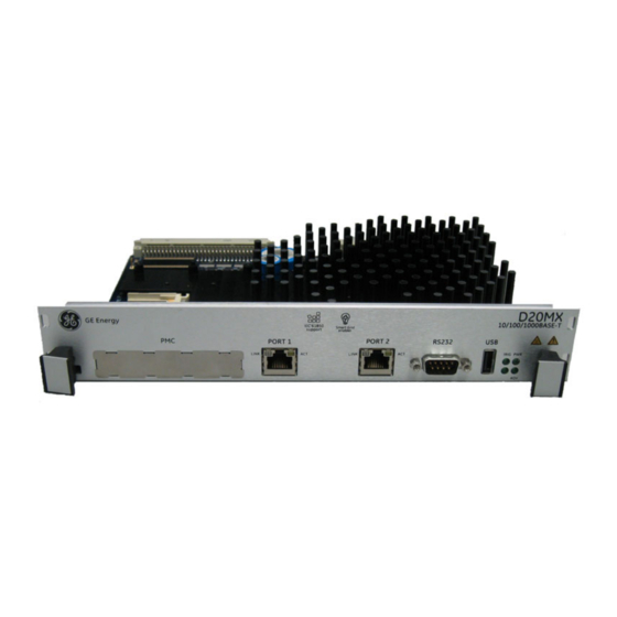
All physical connections are made to the connectors on the rear backplane of the D20 chassis or to the front on the D20MX processor module. D20MX front panel connectors The D20MX front panel can have one of the following layouts: • Ethernet connectors (RJ45); see Figure 14. -
Page 40: General Cabling Requirements
Optic Serial Port Status LEDs Status Port 1 Port 2 supported) LEDs Figure 16: D20MX front panel and fiber optic card with rear access fiber optic connectors Fiber Optic card, D20 chassis back view Fiber Optic Port 1 Fiber Optic... -
Page 41: Link
(TXD, RXD, RTS#, CTS#, DCD#) DTE serial ports, compliant to ANSI/TIA-232 and TIA/EIA-694 specifications and are hosted by UARTs. The D20MX is tested with all 7 serial ports running at 19200 baud with 20% CPU utilization. Refer to application configuration guides for supported baud rates and for data bits. -
Page 42: Twisted-Pair Ethernet (For 526-3001 Only)
Plug network cables into the D20MX twisted-pair Ethernet ports. to network devices If the D20MX is deployed in the presence of strong RF energy in the 110 MHz - 125 MHz band, such as airport ILS localizers or aviation radio transmitters, it is recommended that shielded twisted-pair Ethernet cables be used. -
Page 43: Fiber Optic Ethernet (For 526-3003 And 526-3005Lf Only)
Fiber optic Ethernet (for 526-3003 and 526-3005LF only) The 100BASE-FX variant of the D20MX (GE part numbers 526-3003 and 526-3005) can connect to one or two networks through two fiber-optic Ethernet connections. The data rate on each port is 100 Mbps. -
Page 44: Lan Redundancy
When the primary port (that is, port 1) receives no signal, or detects a fault signal from the remote link partner, the D20MX switches to the secondary port (that is, port 2) if it has a valid link. The D20MX reverts to the primary port if the primary link is restored or no signal is present on the secondary port. - Page 45 D20 Host Name with a two character suffix that matches the derived IP address you wish to override or disable. The suffix conventions are shown in Table 16. The D20 Host Name appears in the D20 Device Wizard as shown in Figure 18. D20MX HARDWARE USER’S MANUAL GENERAL...
- Page 46 CCU B, LAN B FAC_DEFBB The D20MX can be in one of five modes as defined in Table 17. You can find the current mode of the D20MX by navigating to the SHELL in WESMAINT II+ and typing the command...
-
Page 47: Rs-232
WESMAINT II+ facility. SGConfig's Terminal Emulator is an example of a suitable terminal emulation program. The RS-232 port is connected to the D20MX front panel and is also routed to the rear panel as (COM0). The default baud rate is 19,200. - Page 48 Figure 20: Redundant D20 system - If CCU A fails To Field Equipment RS-232 Switch Panel CCU A Serial CCU B Serial Communications Communications RS-232 Switch Monitor and Control CCU A CCU B (F ailed) (Active) Inter-CCU Communications GENERAL D20MX HARDWARE USER’S MANUAL...
-
Page 49: Failover Sequence
Pins 4 on switch panel connectors J2 through J9 are tied together and to the panel’s power supply. Any loading from field devices on these pins will load the RS-232 panel power supply and should be taken into consideration when sizing power supplies. D20MX HARDWARE USER’S MANUAL GENERAL... -
Page 50: Rs-232 Switch Panel Operation
The CCU A/CCU B LED indicator indicates which unit has been activated. Redundancy wiring diagrams Figure 22 illustrates how to wire the D20MX units and RS-232 switch panels to enable system redundancy: The D20MX watchdog (control) port, heartbeat (ping) port, and serial port assignments are software configurable. -
Page 51: D20Mx Hardware User's Manual General
CHAPTER 3: CONNECTING TO DEVICES AND NETWORKS Figure 22: Redundancy wiring - single RS-232 switch panel D20MX HARDWARE USER’S MANUAL GENERAL... - Page 52 CHAPTER 3: CONNECTING TO DEVICES AND NETWORKS GENERAL D20MX HARDWARE USER’S MANUAL...
-
Page 53: Powering-Up And Testing
Before any of the tests and procedures in this section can be performed, a valid configuration file must be loaded into the D20MX NVRAM. If you have replaced the main board of the D20MX, then you will need to restore the configuration file so that diagnostic tests can be performed. -
Page 54: Terminal Emulation
“Set up a PC to act as a WESMAINTII+ terminal”. See page 55. “Power up the D20MX” on page 55. See page 55. Result: The D20MX automatically runs the Online Start-up test. See “Automatic on-line start-up test” on page 55. -
Page 55: Set Up A Pc To Act As A Wesmaintii+ Terminal
• CPU Core Speed The NVRAM CRC test verifies that the configuration header is valid. If this fails, then the D20MX starts with a minimal set of applications that allow the system to be restored. D20MX HARDWARE USER’S MANUAL GENERAL... -
Page 56: Code And Configuration Files
CCU A is Active. Both the PWR A and PWR B LEDs should be illuminated. Connect a NULL modem cable (GE Energy part number 977-0529) to the RS-232 connector on the front panel of the active D20MX. Attach the other end of the cable to the serial communications port of the PC or terminal. -
Page 57: Check That Fail-Over Is Functioning Correctly
CCU A is Active. Both the PWR A and PWR B LEDs should be illuminated. To simulate hardware failure, switch off the Active D20MX at the main power switch on the front of the unit. Result: If the RS-232 is functioning correctly, then it will switch over to the Standby unit and the CCU B LED will illuminate and the CCU A LED will go off. -
Page 58: Verify Either Hardware Or Software Switch-Over
To verify either hardware or software switch-over. Connect a NULL modem cable (GE Energy part number 977-0529) to the RS-232 connector on the front panel of the D20MX designated as CCU B, which was originally the Standby unit. Attach the other end of the cable to the serial communications port of the PC or terminal. -
Page 59: Configuring The Software
An introduction to the software components used in the D20MX. • An overview of the software tools you will use. • How to download image files to the Flash memory on your D20MX module on your system using a serial or network connection. • A description of the SGConfig firmware options •... -
Page 60: Default User
CHAPTER 5: CONFIGURING THE SOFTWARE When RADIUS is used, your RADIUS server provides a role ID to the D20MX. The role ID defines which commands and displays the user is allowed to access while logged in to the D20MX. To allow your RADIUS server to provide a role ID, configure your RADIUS server to use the GE vendor profile that is common to many Multilin products. -
Page 61: Download Image Files To The D20Mx
This file will be named: vxWorks. • A NULL modem cable (GE Energy part number 977-0529) connecting the RS-232 connector on the front panel of the D20MX to the serial communications port of a PC or terminal. • The D20MX module must be installed into a D20 chassis, ready to power-up. -
Page 62: Download Software Over A Serial Connection
To set up the Tera Term on a PC: Connect a NULL modem cable (GE Energy part number 977-0529) from the RS-232 connector on the front panel of the D20MX to the serial communications port of the PC or terminal. - Page 63 Press Enter to verify that communication is active. Result: The D20M> prompt appears if the connection is active. 5.2. Type rz and press Enter to put the D20MX into the state where it is ready to receive the downloadable code file 5.3.
-
Page 64: Download Software Over A Network Connection
Type el /r to ensure that log is clear. Type boot to restart device. Result: The image file load is completed. The flash memory of the D20MX now has the new application and optional operating system image file loaded. Configuration File... -
Page 65: Sgconfig Firmware Options
This allows for seamless migration from older D20ME firmware. The actual firmware on the D20MX supports both SGConfig firmware options. Accordingly, there is no need to perform a firmware transfer to change the D20MX firmware when changing between SGConfig firmware options. -
Page 66: Update To The San0001 Firmware Option
SANnnnn firmware option Update to the SAN0001 firmware option If the D20MX was ordered with the SAN0002 SGConfig firmware option and migration from older firmware is not required or the latest application versions are required, the following procedure can be followed to update your D20MX configuration to the SGConfig SAN0001 firmware option. - Page 67 10. Generate Project, 10.1. Select the Project: TEST_PROJ tab. 10.2. Click: the D20 device. 10.3. Click the ribbon Configure group > Generate. 10.4. Confirm that there are zero errors in the Device Log; any Warnings are acceptable. D20MX HARDWARE USER’S MANUAL GENERAL...
-
Page 68: Transfer D20/D200 Configurations To The D20Mx
If you are transferring a D200 device configuration, follow the steps in the following sections: • Section: “Transferring a D200 configuration to the D20MX” on page 74 • Section: “Transferring a D20 configuration to the D20MX” on page 69 GENERAL... -
Page 69: Transferring A D20 Configuration To The D20Mx
• SGConfig 7.00 or higher installed on the configuration computer. • The D20MX Documentation CD (part number 588-0075/00) installed in a CD/DVD drive of the configuration computer. • D20 Configuration has been migrated to SGConfig with the Migration Wizard (Refer to the Migration Wizard screencast). - Page 70 7.6. Browse to a folder and click OK, OK and OK. Result: The main page of the project appears. Close the D20MX Factory Default Configuration (i.e. SAG0001 or SAG0002): 8.1. Click GE > Close Project. Result: The Close Project window appears.
- Page 71 11.6. Click the Processor tab > General sub-tab. 11.7. From the Part Number field, click Select. Result: The Select a Processor Card window appears. 11.8. Select one of the three D20MX processor type part numbers (526-3001, 526- 3003 or 526-3005). 11.9. Click Next, Next, Firmware tab, Select.
- Page 72 Result: A warning dialog appears. 14.5. Click Yes. Result: The warning dialog and the Application list popup disappear. 15. Import the RADIUS roles from the D20MX default configuration into the D20 device: 15.1. Double-click the D20 device. Result: The Application List popup appears.
- Page 73 Table, TLS Auth Info Table, TLS CA Info Table, First PEM File Table, Second PEM File Table and Login Warning Banner Table, referring to the B014-1NCG WESMAINT II+ configuration guide. 19. Generate the iSCS Configuration for the Project: 19.1. Click the Project tab of the original D20 device configuration. D20MX HARDWARE USER’S MANUAL GENERAL...
-
Page 74: Transferring A D200 Configuration To The D20Mx
22. Note that all users that existed in the transferred D20/D200 configuration will now have a default password of “changeme”. Change these passwords using the passwd command in the D20MX Shell. Refer to the WESMAINT Configuration Guide B014- 0NCG for details of this command. -
Page 75: Updating D20/D200 Configurations To Use The D20Mx Firmware Definition With Configpro
D20 in the instructions below. Single and multi-processor D200 devices must first be changed into D20 devices before the D20MX processor card option can be selected. To change a D200 device into a D20 device perform the following steps: Start SGConfig. -
Page 76: Configpro
10. Change the Project Name if desired and click OK. Result: The main window of ConfigPro appears with the tree view of the project directory on the left. The new D20MX factory default project appears in the tree view. 11. Double-click on the D20MX factory default project. - Page 77 FAC_DEF device appear. 16. Close the device configuration by clicking on the door icon. Result: The Main Page of the D20MX factory default project appears with the FAC_DEF device appearing on the page. 17. Click from the menu bar, Device > Firmware.
- Page 78 D20 in the instructions below. Single and multi-processor D200 devices must first be changed into D20 devices before the D20MX firmware definition can be selected. To change a D200 device into a D20 device perform the following steps: Start ConfigPro 5.03 or higher.
- Page 79 Right-click on the D20 device you want to transfer and select Tools > Change. Result: The Change Device window appears. Select type D20 and click OK. Follow the steps in section: “Updating a D20 configuration to use the D20MX firmware definition with ConfigPro” on page 76. D20MX HARDWARE USER’S MANUAL...
- Page 80 CHAPTER 5: CONFIGURING THE SOFTWARE GENERAL D20MX HARDWARE USER’S MANUAL...
-
Page 81: Using The D20Mx
• Fiber optic status port LEDs Front panel LEDs Once the D20MX is powered up, the LED indicators on the front panel become active. The indicators provide status information on the operation of the D20MX. Operational status LEDs The status LEDs indicate the unit’s operational status:... -
Page 82: Lan Port Status Leds
Normally off; reserved for future expansion. IRIG IRIG LAN port status LEDs The LAN Port Status LEDs provide a visual indication of the status for the Ethernet communication ports on the front of the D20MX. LED Display Label Color Status Description LINK Orange for 1000BASE-T. -
Page 83: Servicing The D20Mx
Connectors and cables are intact and firmly attached Removing the D20MX processor module The D20MX can be removed from a non-VME (GE part number 500-0305) or VME (GE part number 500-0280) D20 chassis. Ensure that you are sufficiently grounded to prevent ESD damage to the D20MX or other components. - Page 84 6.5. Store the D20MX fiber card in static-protective packaging. Grasp the D20MX by the front handles and slide the processor module all the way out of the D20 chassis. Allow the D20MX to cool before removing. The heatsink of the D20MX may be extremely hot during and immediately after operation.
-
Page 85: Default Role- Based Access Control Model
Default Role-Based Access Control Model Configured roles in the D20MX When you configure the D20MX to use RADIUS, the D20MX must be configured with a set of roles in the B014 RADIUS Roles Table (B014RADR) of the WESMAINT II+ application (Refer to the B014-1NCG WESMAINT II+ for the D20MX Configuration Guide for more information). - Page 86 Digital Inputs display Digital Inputs Detail display Digital Outputs display Digital Outputs Detail display Analog Inputs display Analog Inputs Detail display Analog Outputs display Analog Outputs Detail display Transition Counter display Transition Counter Detailed display GENERAL D20MX HARDWARE USER’S MANUAL...
- Page 87 Observer Position 0-31 Not Used Table 28: Read access flags for Prologic display (Application number: 36) Description Administrator Engineer Operator Observer Position Connect to Prologic Editor Request Control of Port 2 - 31 Not Used D20MX HARDWARE USER’S MANUAL GENERAL...
- Page 88 32013) Description Administrator Engineer Operator Observer Position Any Page 2 - 31 Not Used Table 35: Modify access flags for Modbus DCA display (Application number: 59) Description Administrator Engineer Operator Observer Position 0-31 Not Used GENERAL D20MX HARDWARE USER’S MANUAL...
- Page 89 Table 41: Modify access flags for SOE Logger (Application number: 27) Description Administrator Engineer Operator Observer Position 0-31 Not Used Table 42: Read modify access flags for SOE Logger (Application number: 27) Description Administrator Engineer Operator Observer Position Any Page 2 - 31 Not Used D20MX HARDWARE USER’S MANUAL GENERAL...
- Page 90 APPENDIX A: DEFAULT ROLE-BASED ACCESS CONTROL MODEL GENERAL D20MX HARDWARE USER’S MANUAL...
-
Page 91: Standards & Compliance Standards
D20MX Processor Appendix B: Standards & Protection Standards & Protection This Appendix lists the standards with which the D20MX has been tested for compliance. Compliance standards Compliance standards are listed for the following categories: • Emission standards; see Table 43 •... - Page 92 Pulse shape: Half sine Pulse duration: 16 mS Acceleration level: 10 g's 1000 pulses per polarity per axis for a total of 6000 pulses IEC 60068-2-30 Damp heat, cyclic (12 h + 12 h cycle) GENERAL D20MX HARDWARE USER’S MANUAL...
- Page 93 1 To comply, the D20MX BIOS Spread Spectrum clock setting must be set to “disable”. This is the factory default. 2 To comply, the D20MX BIOS DRAM clock setting must be set to “HCLK-33M”. This is the factory default. D20MX HARDWARE USER’S MANUAL...
- Page 94 APPENDIX A: STANDARDS & PROTECTION GENERAL D20MX HARDWARE USER’S MANUAL...
-
Page 95: List Of Acronyms
- an electrical power unit in decibel (dB) Data Collection Application Data Carrier Detect Distributed Network Protocol Data Processing Application Data Terminal Equipment Electronic Industries Alliance Electromagnetic Capability Electromagnetic Interference EPUP Environmental Protection Use Period ElectroStatic Discharge D20MX HARDWARE USER’S MANUAL GENERAL... - Page 96 Restriction of Hazardous Substances Request To Send Remote Terminal Unit Receive Receive Data SCADA Supervisory Control and Data Acquisition SNTP Simple Network Time Protocol Sequence Of Events SQL™ Structured Query Language Telecommunication Industries Association Transmit Transmit Data GENERAL D20MX HARDWARE USER’S MANUAL...
- Page 97 APPENDIX B: LIST OF ACRONYMS Acronym Definition UART Universal Asynchronous Receiver-Transmitter Unshielded Twisted Pair Volt Amps, unit of measure V AC Volts, Alternating Current, unit of measure V DC Volts, Direct Current, unit of measure Versa Module Eurocard D20MX HARDWARE USER’S MANUAL GENERAL...
- Page 98 APPENDIX B: LIST OF ACRONYMS GENERAL D20MX HARDWARE USER’S MANUAL...
- Page 99 ....................21 FAIL-OVER CHECK ..................57 peripherals ....................22 FIBER OPTIC power supplies ..................20 cabling ......................43 system redundancy ................47 port LEDs ....................82 D20 CHASSIS LAYOUTS ................. 29 FILES D20 NON-VME CHASSIS OVERVIEW ..........18 D20MX HARDWARE USER’S MANUAL GENERAL...
- Page 100 ..............64 OPERATIONAL LEDS ................81 download over serial ................62 OVERVIEW introduction .....................59 cabling .......................39 specifications ..................26 D20 chassis ....................18 Tera Term set up ..................62 D20MX processor ..................15 when to download ................61 product ......................15 SOFTWARE APPLICATIONS ..............16 GENERAL D20MX HARDWARE USER’S MANUAL...
- Page 101 UNPACKING THE D20MX ..............36 UPDATE D20/D200 CONFIGURATIONS ........75 UPDATE FIRMWARE OPTIONS ............66 UPGRADE FIRMWARE ................12 UPGRADE KITS ................... 24 USER ACCOUNTS local ......................59 remote ....................... 59 VERSIONS firmware ....................17 D20MX HARDWARE USER’S MANUAL GENERAL...
- Page 102 INDEX GENERAL D20MX HARDWARE USER’S MANUAL...
-
Page 103: Modification Record
Added sections for: Update to the SAN0001 firmware option, Transfer D20/ D200 configurations to the D20MX, and Updating D20/D200 Configurations to use the D20MX firmware definition with ConfigPro. Added an Appendix for Resetting a read/write user password. D20MX HARDWARE USER’S MANUAL... - Page 104 GENERAL D20MX HARDWARE USER’S MANUAL...