Table of Contents
Advertisement
Advertisement
Table of Contents

Related Manuals for Motorola xfinity RNG150N


Summary of Contents for Motorola xfinity RNG150N
- Page 1 U S E R G U I D E RNG150N...
-
Page 3: Important Safety Instructions
IMPORTANT SAFETY INSTRUCTIONS • Read these instructions. • Keep these instructions. • Heed all warnings. • Follow all instructions. • Do not use this apparatus near water. • Clean only with dry cloth. • Do not block any ventilation openings. Install in accordance with the manufacturer’s instructions. -
Page 4: Important Safety Considerations
IMPORTANT SAFETY CONSIDERATIONS • The mains plug is the main disconnect device. It shall remain readily accessible and operable. • The apparatus shall not be exposed to dripping or splashing and no objects filled with liquids, such as vases, shall be placed on the apparatus. During Transportation to the Subscriber Home •... -
Page 5: Fcc Compliance
FCC DECLARATION OF CONFORMITY Motorola Mobility Inc., 101 Tournament Drive, Horsham, PA 19044, 1-215-323- 1000, declares that the RNG150N set-top complies with 47 CFR Parts 2 and 15 of the FCC rules as a Class B digital device. Industry Canada (IC) This Class B digital device complies with Canadian ICES-003. - Page 6 Software. The Software is never sold. Motorola licenses the Software to the original customer and to any subsequent licensee for personal use only on the terms of this License. Motorola and its third party licensors retain the ownership of the Software.
- Page 7 THIS LICENSE SHALL TERMINATE AUTOMATICALLY if you fail to comply with the terms of this License. Motorola is not responsible for any third party software that is provided as a bundled application, or otherwise, with the Software or that is downloaded to, or...
- Page 8 Motorola reserves the right to revise this publication and to make changes in content from time to time without obligation on the part of Motorola to provide notification of such revision or change. Motorola provides this guide without warranty of any kind, implied or expressed, including, but not limited to, the implied warranties of merchantability and fitness for a particular purpose.
-
Page 9: Table Of Contents
CONTENTS 1 Introduction ........................... 1 Features ............................ 1 Front Panel ..........................2 Rear Panel ..........................3 2 Operation............................5 Turning Power On and Off ..................... 5 Changing Channels ......................... 5 Adjusting the Volume ......................5 Interactive Program Guide ....................5 M-Card™... - Page 10 Data Features ........................24 5 On-Screen Graphics ........................25 6 Configuring the audio, video, and closed caption settings ........... 27 7 Troubleshooting .......................... 41 viii...
-
Page 11: Introduction
1 INTRODUCTION Congratulations on receiving a Motorola RNG150N High-Definition All- Digital Cable Set-top box, one of the most advanced interactive digital cable set-tops available today. Motorola has merged the extraordinary features of digital cable — the seemingly endless programming options,... -
Page 12: Front Panel
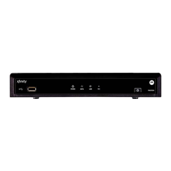
1 INTRODUCTION Front Panel USB connector* Power LED — Illuminates when the set-top is powered on Data — Dual function LED • Flashes to indicate unit is booting/provisioning • Extinguished when unit is provisioned LAN — Illuminates to indicate one or more set-top boxes and/or DVR devices are detected on the home network Rec —... -
Page 13: Rear Panel
1 INTRODUCTION Rear Panel Cable In — Connects to cable signal from the service provider Ext IR Input – Connects to a remote control receiver accessory cable IEEE-1394 — Audio and video device connection M-Card — Inserted M-Card Serial — Data test connector (service personnel only) S-Video —... -
Page 15: Operation
2 OPERATION Turning Power On and Off Press POWER on the front panel or the remote control to turn the RNG set-top on or off (standby). Be sure the remote control is in cable mode by pressing CABLE before pressing POWER. Changing Channels You can change channels in three ways: •... -
Page 17: Connecting Your Rng Set-Top
3 CONNECTING YOUR RNG SET-TOP Instructions and diagrams are included for the following connections: • High-Definition TV (HDTV) • A/V receiver — Audio • Standard-Definition TV (SDTV) • Standard-Definition TV (SDTV) and VCR/DVD Recorder • A/V receiver, Standard-Definition TV (SDTV), and VCR/DVD Recorder Before you move or change components on your entertainment system, review the following:... - Page 18 3 CONNECTING YOUR RNG SET-TOP • HDMI or IEEE-1394 — HDTV and SDTV HDMI and IEEE-1394 offer higher quality HD video than component video. If your TV has an HDMI input, this is for both audio and video. Connect a Standard HDMI cable to the TV and to the HDMI connector on your RNG set-top.
-
Page 19: Connecting Hdtv - Single Connection For Video/Audio
3 CONNECTING YOUR RNG SET-TOP • Composite Video (also referred to as Video) — SDTV If an S-Video input is not available on your TV, use the composite video (video) connection. Note: Composite video does not provide audio. A separate audio connection must be made. -
Page 20: Connecting Your Rng Set-Top To An Hdtv - Single Connection For Video/Audio
3 CONNECTING YOUR RNG SET-TOP Connecting Your RNG Set-top to an HDTV — Single Connection for Video/Audio Note: Only (1) HDTV video/audio connection needs to be made to an HDTV. Note: On screen graphics will not be displayed when using IEEE-1394 connection. -
Page 21: Connecting Hdtv - Separate Video/Audio Connections
3 CONNECTING YOUR RNG SET-TOP Connecting HDTV — Separate Video/Audio Connections Cable In Connect an RF coaxial cable to the cable wall outlet and the CABLE IN connector on the RNG set-top and then choose one of the following: If your TV has a DVI input, use the DVI connection for your video, connect a HDMI-to-DVI adapter or cable to the HDMI out connector on the RNG set-top and the DVI-HDTV connector on your TV. -
Page 22: Audio
Audio If your TV does not have digital audio inputs, connect the stereo audio cable to the AUDIO L/R connectors on the RNG150N set-top and the AUDIO L/R connectors on the HDTV. If your TV supports digital audio inputs, use the digital audio OPTICAL S/PDIF or COAXIAL S/PDIF outputs instead of the AUDIO L/R outputs. -
Page 23: Connecting Your Rng Set-Top To An Hdtv - Separate Video/Audio
3 CONNECTING YOUR RNG SET-TOP Connecting Your RNG Set-top to an HDTV — Separate Video/Audio Note: Only (1) video connection and (1) audio connection needs to be made to an HDTV. Note: Solid lines indicate optimum connections. Note: HDMI-to-DVI adapter is not included with the set-top. -
Page 24: Connecting Your Rng Set-Top To An Hdtv - Alternative Audio
3 CONNECTING YOUR RNG SET-TOP Connecting Your RNG Set-top to an HDTV — Alternative Audio Note: Only (1) audio connection needs to be made. Note: Solid lines indicate optimum connections. -
Page 25: Connecting An A/V Receiver - Audio
3 CONNECTING YOUR RNG SET-TOP Connecting an A/V Receiver — Audio There are several options available for audio connections to your A/V receiver: • Digital audio (OPTICAL S/PDIF) • Digital audio (COAXIAL S/PDIF) • Stereo audio (AUDIO L/R) If your A/V receiver supports it, the optical (S/PDIF) or coaxial (S/PDIF) digital audio outputs may be used in place of the stereo audio outputs (AUDIO L/R). -
Page 26: Connecting Your Rng Set-Top To An A/V Receiver - Audio
3 CONNECTING YOUR RNG SET-TOP Connecting Your RNG Set-top to an A/V Receiver — Audio Note: Only (1) audio connection needs to be made to an A/V Receiver. Note: Solid lines indicate optimum connections. -
Page 27: Connecting An Sdtv
3 CONNECTING YOUR RNG SET-TOP Connecting an SDTV Connect the stereo audio cable to the AUDIO L/R connectors on the RNG set-top and the AUDIO L/R connectors on the Standard-Definition TV (SDTV). Connect an S-Video cable to the S-Video out connector on the RNG set-top and the input S-Video on the TV. -
Page 28: Connecting Your Rng Set-Top To An Sdtv
3 CONNECTING YOUR RNG SET-TOP Connecting Your RNG Set-top to an SDTV Note: S-Video and Composite video require separate audio connections. Note: Only (1) video connection and (1) audio connection is required. Note: Solid lines indicate optimum connections. -
Page 29: Connecting An Sdtv And Vcr/Dvd Recorder
RNG150N set-top and the INPUT AUDIO L/R connectors on the VCR/DVD recorder. Connect a composite video cable to the VIDEO OUT connector on the RNG150N set-top and the INPUT VIDEO connector on the VCR/DVD recorder. Connect a stereo audio cable to the OUTPUT AUDIO L/R... -
Page 30: Connecting Your Rng Set-Top To An Sdtv And Vcr/Dvd Recorder
3 CONNECTING YOUR RNG SET-TOP Connecting Your RNG Set-top to an SDTV and VCR/DVD Recorder... -
Page 31: Connecting An A/V Receiver, Sdtv, And Vcr/Dvd Recorder
3 CONNECTING YOUR RNG SET-TOP Connecting an A/V Receiver, SDTV, and VCR/DVD Recorder Connect a stereo audio cable to the AUDIO OUT L/R connectors on the RNG set-top and the INPUT L/R connectors on the A/V receiver. Connect an S-Video cable to the S-Video out connector on the RNG set-top and the S-Video connector on the A/V receiver. -
Page 32: Connecting Your Rng Set-Top To An A/V Receiver, Sdtv, And Vcr/Dvd Recorder
3 CONNECTING YOUR RNG SET-TOP Connecting Your RNG Set-top to an A/V Receiver, SDTV, and VCR/DVD Recorder Note: Solid lines indicate optimum connections. Note: Consult your A/V receiver manual for additional wiring options or constraints when including a VCR/DVD recorder in your configuration. -
Page 33: Recording Your Connections
4 RECORDING YOUR CONNECTIONS Use this diagram to record connections between your home entertainment components. You can use this diagram to reconnect your system if you move the equipment or add new equipment. Disconnect the power from the RNG set-top before connecting or changing cable connections. -
Page 34: Data Devices
4 RECORDING YOUR CONNECTIONS Data Devices Note: Do not attempt to connect data devices without contacting your service provider. Advanced data features require the proper application and network infrastructure to operate. Data Features In addition to high-quality audio and video, the RNG set-top has the capability to deliver high-speed data services such as Internet access, e-mail, IP telephony, e-commerce, and home banking. -
Page 35: On-Screen Graphics
5 ON-SCREEN GRAPHICS Your RNG set-top can generate graphics that overlay the video programming or fill the entire television screen. Common examples include on-screen menus (such as the User Setting menu), closed captions, and interactive program guides. The RNG set-top overlays these graphics whenever you open a menu, enable closed captions, or scroll through a program grid. -
Page 37: Configuring The Audio, Video, And Closed Caption Settings
Standard HDMI cables for 1080i or 720p resolutions. A certified High Speed HDMI cable is recommended for resolutions of 1080p. To configure the RNG150N settings on the User Settings menu screen: Power off the RNG set-top and then immediately press the menu key on the remote control. - Page 38 6 CONFIGURING THE AUDIO, VIDEO, AND CLOSED CAPTION SETTINGS Note: The User Settings menu indicates whenever an HDMI connection is in place between the RNG150N and another device. When the HDMI connection is not being used the User Settings Menu...
- Page 39 Description TV Type The TV Type allows you to specify the style of television connected to the RNG150N. Options include 16:9, 4:3 LETTERBOX, and 4:3 PAN SCAN. By default, the 16:9 option is selected. The options are used as follows: •...
- Page 40 Description HDMI / The HDMI/YPbPr Output setting allows you to YPbPr specify the video output format of the RNG150N for Output all programs (when the 4:3 Override setting is set Off or Stretch) or for all widescreen programs (when the 4:3 Override is set to 480i or 480p). Options include 1080i, 720p, 480p, 480i, and Native.
- Page 41 Description The 4:3 Override setting allows you to specify the Override video output format of the RNG150N when it is tuned to a Standard-Definition program or playing back a Standard- Definition program from the DVR. Options include 480i, 480p, Stretch, and Off. By default, the 480i option is selected.
- Page 42 Following accessible only when the HDMI/YPbPr Output Formats setting is set to Native. The RNG150N is capable of delivering all of the video formats listed in this checklist depending upon the type of video connection (HDMI or YPbPr) being used. By default, the 1080i and 480i formats are checked in this checklist.
- Page 43 3. While this checklist provides the ability to customize the Native mode experience when using the RNG150N, it can also result in a loss of video if the checklist is modified without a clear understanding of the video formats supported by the TV.
- Page 44 The Closed Caption setting turns closed captions off Caption or on. When this option is set to Disabled, the RNG150N does not render (draws) closed captions on any video output. When this option is set to Enabled, the RNG150N renders (draws) closed captions on all video outputs.
- Page 45 6 CONFIGURING THE AUDIO, VIDEO, AND CLOSED CAPTION SETTINGS To configure the RNG150N settings on the Additional HDMI Settings menu screen: With an HDMI connection in place, power off the RNG150N and then immediately press the MENU key on the remote control.
- Page 46 Color Space The Color Space setting allows you to adjust the color space used by the RNG150N to generate the video signals on the HDMI output. By default, this option is set to YCC 4:4:4. The options are used as follows: •...
- Page 47 The Audio Output setting allows you to specify the Output digital audio format delivered over the HDMI connection by the RNG150N. Options include Auto, L-PCM, and Pass Through. By default, the Auto option is selected. The options are used as follows: •...
- Page 48 6 CONFIGURING THE AUDIO, VIDEO, AND CLOSED CAPTION SETTINGS To configure the RNG150N settings on the Additional Closed Caption Settings menu screen: Power off the RNG150N and then immediately press the MENU key on the remote control. This will display the main User Settings menu.
- Page 49 6 CONFIGURING THE AUDIO, VIDEO, AND CLOSED CAPTION SETTINGS Setting Description Font Style Sets the font style for closed captions. Defaults to AUTO. Options are AUTO, MONO SERIF, PROPORTION SERIF, MONO NO SERIF, PROPORTION NO SERIF, CASUAL, CURSIVE, or SMALL. Font Color Sets the font color.
-
Page 51: Troubleshooting
7 TROUBLESHOOTING Before calling your service provider, review this troubleshooting guide. This information is to help you quickly solve a problem. If your problem still exists, contact your service provider. Problem Possible Solution The RNG set- The RNG set-top may have received a software top will not update and may not power on while the new power on... - Page 52 7 TROUBLESHOOTING Problem Possible Solution There is no Verify that the mute button on the remote control audio when has not been pressed. Press mute on the remote viewing cable control to restore sound. channels • If the RNG set-top audio output is connected to the TV, verify that the mute button on the TV has not been pressed.
- Page 53 7 TROUBLESHOOTING Problem Possible Solution There is no Verify that the TV is powered on and set to the video on the appropriate input source for the RNG set-top. TV screen Verify that the RNG set-top is powered on and tuned to an authorized cable channel.
- Page 54 (see your TV manual for information about stretching 4:3 video). • If the RNG150N is connected to a wide screen TV, verify that the TV TYPE is set to 16:9 in the User Settings menu.
- Page 55 “hybrid” aspect ratio and results in a black border surrounding the video on a 4:3 TV. Because this is part of the broadcast, the RNG150N cannot correct the video. You may be able to minimize the border using the zoom feature on the TV.
- Page 57 Motorola Mobility, Inc. 101 Tournament Drive Horsham, PA 19044 U.S.A. http://www.motorola.com 571331-001-c 10/10...