TP-Link TL-SG1048 Installation Manual
Gigabit unmanaged switch
Hide thumbs
Also See for TL-SG1048:
- Installation manual (32 pages) ,
- Installation manual (24 pages) ,
- Installation manual (32 pages)

Related Manuals for TP-Link TL-SG1048


Summary of Contents for TP-Link TL-SG1048
- Page 1 Enterprise Networking Solution Installation Guide Gigabit Unmanaged Switch TL-SG1048 TL-SG1024/TL-SG1024D TL-SG1016/TL-SG1016D TL-SG1008/TL-SG1008PE...
-
Page 3: Fcc Statement
COPYRIGHT & TRADEMARKS Specifications are subject to change without notice. is a registered trademark of TP-LINK TECHNOLOGIES CO., LTD. Other brands and product names are trademarks of their respective holders. No part of the specifications may be reproduced in any form or by any means or used to make any derivative such as translation, transformation, or adaptation without permission from TP-LINK TECHNOLOGIES CO., LTD. - Page 4 Related Document This Installation Guide is also available in PDF on our website. To obtain the latest documentation and product information, please visit the official website: http://www.tp-link.com About this Installation Guide This Installation Guide describes the hardware characteristics, installation methods and the points that should be attended to during the installation.
-
Page 5: Table Of Contents
Contents Introduction ——————————— 01 Chapter 1 Product Overview ..............01 Features ..................01 Appearance ................02 Installation ———————————— 08 Chapter 2 Package Contents ..............08 Safety Precautions ..............08 Installation Tools..............10 Product Installation ..............11 Lightning Protection ———————— 13 Chapter 3 Cabling Reasonably..............13 Connect to Ground..............15 Equipotential Bonding ............16 Use Lightning Arrester ............17 Connection ———————————... -
Page 6: Introduction
*PD is a device powered by a PSE and thus consumes energy. Examples include ■ powering IP telephones, wireless LAN access points, network cameras, network hubs, embedded computers etc. Features For TL-SG1048/TL-SG1024/TL-SG1024D/TL-SG1016/TL-SG1016D/TL-SG1008: • Complies with IEEE802.3, IEEE802.3u, IEEE802.3ab standards • 8/16/24/48 10/100/1000Mbps Auto-Sense RJ45 ports supporting Auto-MDI/MDIX •... -
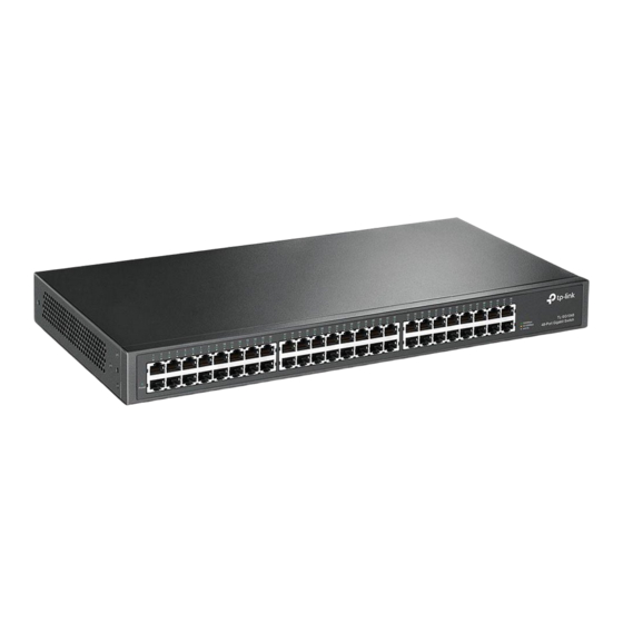
Page 7: Appearance
8K entry MAC address table of the TL-SG1008PE with auto-learning and auto-aging • Internal power supply ACCearance Front Panel ■ The front panel of TL-SG1048 is shown as the following figure. LEDs 10/100/1000Mbps RJ45 Port Figure 1-1 Front Panel of TL-SG1048 LEDs... - Page 8 Gigabit Unmanaged Switch 10/100/1000Mbps RJ45 Port Designed to connect to the device with a bandwidth of 10Mbps, 100Mbps or 1000Mbps. Each has a corresponding Link/Act LED. The front panel of TL-SG1024 is shown as the following figure. LEDs 10/100/1000Mbps RJ45 Port Figure 1-2 Front Panel of TL-SG1024 The front panel of TL-SG1016 is shown as the following figure.
- Page 9 Gigabit Unmanaged Switch The front panel of TL-SG1008 is shown as the following figure. LEDs 10/100/1000Mbps RJ45 Port Figure 1-6 Front Panel of TL-SG1008 LEDs Status Indication The switch is powered on. Power The switch is powered off or power supply is abnormal. There is a device linked to the corresponding port but no activity.
- Page 10 Gigabit Unmanaged Switch Status Indication The power of all the connected PoE ports is between On (red1 118W and 124W. No power may be supplied if additional PDs are connected. PoE MAX Flashing (red1 The power of all the connected PoE ports is >=124W. The power of all the connected PoE ports is <118W, or there is no PD connected to the corresponding port.
-
Page 11: Rear Panel
Gigabit Unmanaged Switch Rear Panel The rear panel of TL-SG1048 is shown as the following figure. Power Socket Grounding Terminal Figure 1-8 Rear Panel of TL-SG1048 The rear panel of TL-SG1024/TL-SG1016 is shown as the following figure. Power Socket Grounding Terminal... - Page 12 Gigabit Unmanaged Switch Power Socket Connect the female connector of the power cord here, and the male connector to the AC (Alternating Current1 power outlet. Please make sure the voltage of the power supply meets the requirement of the input voltage. Grounding Terminal The Switch already comes with lightning protection mechanism.
-
Page 13: Installation
Gigabit Unmanaged Switch ChaCter 1 Installation Package Contents Make sure that the package contains the following items. If any of the listed items is damaged or missing, please contact your distributor. One Switch One Power Cord This Installation Guide Two mounting brackets and the fittings Safety Precautions To avoid any device damage and bodily injury caused by improper use, please observe... -
Page 14: Site Requirements
Gigabit Unmanaged Switch Site Requirements ■ Temperature/Humidity 40℃ 0℃ Please keep a proper temperature and humidity in the equipment room. Too high/low humidity may lead to bad insulation, electricity leakage, mechanical property changes and corrosions. Too high temperature may accelerate aging of the insulation materials and can thus significantly shorten the service life of the device. -
Page 15: Installation Tools
Gigabit Unmanaged Switch Lightening Protection Extremely high voltage currents can be produced instantly when lightning occurs and the air in the electric discharge path can be instantly heated up to 20,000℃. As this instant current is strong enough to damage electronic devices, more effective lightning protection measures should be taken. -
Page 16: Product Installation
Gigabit Unmanaged Switch Product Installation Desktop Installation ■ To install the device on the desktop, please follow the steps: Set the device on a flat surface strong enough to support the entire weight of the device with all fittings. Remove the adhesive backing papers from the rubber feet. Turnover the device and attach the supplied rubber feet to the recessed areas on the bottom at each corner of the device. - Page 17 Gigabit Unmanaged Switch Rack Figure 2-3 Rack Installation Caution: Please set 5~10cm gaps around the device for air circulation. ■ Please avoid any heavy thing placed on the device. ■ Please mount devices in sequence from the bottom to top of the rack and ensure a ■...
-
Page 18: Chapter 3 Lightning Protection
Gigabit Unmanaged Switch ChaCter 1 Lightning Protection Cabling Reasonably In the actual network environment, you may need cable outdoors and indoors, and the requirements for cabling outdoors and indoors are different. A reasonable cabling system can decrease the damage of induced lightning to devices. Note: It's not recommended using Ethernet cables outdoors. - Page 19 Gigabit Unmanaged Switch Requirements for Cabling Indoors ■ When cabling indoors, keep a certain distance away from the devices that may cause high-frequency interferences, such as down-conductor cable, powerline, power transformer and electromotor. The main cable should be paved in the metal raceway of the access shaft. When ■...
-
Page 20: Connect To Ground
Gigabit Unmanaged Switch Min Parallel Cable Pave Way Length (mm1 Parallel cabling 2~5kVA One is in the grounded metal raceway or metal pipe powerline The both are in the grounded metal raceway or metal pipe Parallel cabling >5kVA One is in the grounded metal raceway or metal pipe powerline The both are in the grounded metal raceway or metal pipe... -
Page 21: Equipotential Bonding
Gigabit Unmanaged Switch Note: The grounding bar and the ground cable are not provided with our product. If needed, please self purchase them. Connecting to the Ground via the Power Supply ■ If the device is installed in the normal environment, the device can be grounded via the PE (Protecting Earth1 cable of the AC power supply as shown in the following figure. -
Page 22: Use Lightning Arrester
Gigabit Unmanaged Switch Grounding Terminal Equipotential Bonding Cable Ground Cable Grounding Bar Figure 3-3 Equipotential Bonding When equipotential bonding, please note that the cable should be copper wrapped Kelly with its area being 6mm at least. The shorter cable the better, and use a grounding bar to establish an equipotential bonding point. - Page 23 Gigabit Unmanaged Switch The port rate of the signal lightning arrester should match the rate of the desired ■ port on the device. If it is not matched, this signal lighting arrester will not work. Purchase a standard lightning arrester. Install signal lightning arrester near the protected device and connect it to the ■...
-
Page 24: Connection
Gigabit Unmanaged Switch ChaCter 2 Connection Ethernet Port Connect a Ethernet port of the Switch to the computer by RJ45 cable as the following figure shown. RJ45 Port RJ45 Cable Figure 4-1 Connecting the RJ45 Port Verify Installation After completing the installation, please verify the following items: There are 5~10cm of clearance around the sides of the device for ventilation and ■... -
Page 25: Initialization
figure above. Initialization For TL-SG1048/TL-SG1024/TL-SG1024D/TL-SG1016/TL-SG1016D/TL-SG1008: After the device is powered on, it begins the Power-On Self-Test. A series of tests run automatically to ensure the device functions properly. During this time, its LED indica-... -
Page 26: Appendix A Troubleshooting
Gigabit Unmanaged Switch ACCendix A Troubleshooting QQQQ The Power LED is not lit The Power LED should be lit up when the power system works normally. If the Power LED worked abnormally, please check as follows: Make sure that the power cable is connected properly, and the power contact is normal. -
Page 27: Appendix B Speci Cations
Gigabit Unmanaged Switch ACCendix B SCecifications Item Content IEEE802.3, IEEE802.3u, IEEE802.3ab, IEEE802.3x Standards IEEE802.3af (for TL-SG1008PE1, IEEE802.3at (for TL-SG1008PE1 UTP/STP of Cat. 3 or above(maximum 100m1 10Base-T For TL-SG1008PE: UTP category 3, 4, 5 cable (maximum 100m1 EIA/TIA-568 100Ω STP (maximum 100m1 2-pair UTP/STP of Cat. -
Page 28: Appendix C Technical Support
Gigabit Unmanaged Switch ACCendix C Technical SuCCort For more troubleshooting help, go to: http://www.tp-link.com/en/support/faq ■ To download the latest Firmware, Driver, Utility and User Guide, go to: ■ http://www.tp-link.com/en/support/download For all other technical support, please contact us by using the following details: ■... - Page 29 Gigabit Unmanaged Switch Poland Tel: +48 (01 801 080 618 / +48 22F 21F 563 (if calls from mobile phone1 E-mail: support.pl@tp-link.com Service time: Monday to Friday, 0F:00 to 1F:00. GMT+1 or GMT+2 (Daylight Saving Time1 France Tel: +33 (01 820 800 860 (French service1 Email: support.fr@tp-link.com Fee: 0.118 EUR/min from France Service time: Monday to Friday, 0F:00 to 18:00.
- Page 32 Website: http://www.tp-link.com E-mail: support@tp-link.com F106504166 Rev: 3.2.0...