Table of Contents
Advertisement
Quick Links
FACTORY AUTHORIZED SERVICE
COFFEE BREWERS
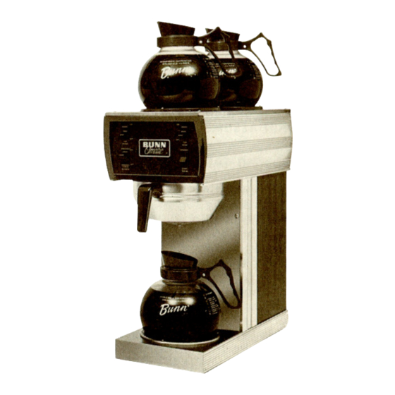
MODELS F-35, F-20, F-15
MODELS ABOVE SERIAL NUMBER*
F·35
57581
F·20
30872
F·15
30179
LISTED
r'pproved
bYe'"''
f(J:\666L
~
~
~
~:~~
F-S
(Stainless)
F-WG
(Woodgrain)
OPERATING
&
SERVICE MANUAL
CONTENTS
Electrician's Insrtallation Instructions
2
Plumber's Installation Instructions
2
Initial Operation Instructions
3
Coffee Brewing Directions
3
CleaningTips
3
Trouble Shooting Guide
4
Component Replacement Instructions
8
Schematic Wiring Diagrams
10
Replacement Parts
11
Warranty
Back Cover
WARNING
DISCARD GLASS DECANTER IF
• CRACKED
• SCRATCHED
• BOILED DRY
• HEATED WHEN EMPTY
• USED ON HIGH FLAME OR OPEN
ELECTRIC ELEMENTS.
FAILURE TO DO SO MAY RESULT
IN BODILY INJURY.
10023.0000E
1/94
©
1981 BUNN-O-MATIC CORPORATION
Advertisement
Table of Contents

Summary of Contents for Bunn F-35
- Page 1 FACTORY AUTHORIZED SERVICE COFFEE BREWERS MODELS F-35, F-20, F-15 MODELS ABOVE SERIAL NUMBER* F·35 57581 F·20 30872 F·15 30179 bYe'"'' ~:~~ f(J:\666L LISTED r'pproved F-WG (Stainless) (Woodgrain) & OPERATING SERVICE MANUAL CONTENTS Electrician's Insrtallation Instructions Trouble Shooting Guide Plumber's Installation Instructions...
-
Page 2: Installation
TAL lA T ION INS T RU CT ION S E l E CT R I C IAN'S MODEL f·35 MODELS f·15 f·20 & ELECTRICAL REQUIREMENTS: • MODELS F35 volts A.C., 60 hertz, 3 wire, single phase. 20 amp. wiring required. 120/240 •... -
Page 3: Coffee Brewing
To decrease amount of water, decrease time of water flow by turning timer dial slightly counterclockwise. 6. Turn control thermostat knob fully clockwise to the ON position. Turn power to brewer ON and allow approximately 10 to 20 minutes for water in tank to heat. (F-35 approximately 10 minutes-F-20 proximately 15 minutes-F-15 approximately 20 minutes.) -
Page 4: Troubleshooting
FACTORY AUTHORIZED SERVICE TROUBLE SHOOTING GUIDE MODELS F·35, F·20, F·15 is depressed, but and water shut off valve. and relay, relay and nections between harness No Water. Be sure water shut Timer. No Power. Loose connection Be sure these con- Should hear two clicks Solenoid valve. - Page 5 FACTORY AUTHORIZED SERVICE '0551 BLE CAUSE WHAT CHECK REMEDY 1. Tank heater NO HOT 1. Voltage at tank heater 1. If correct voltage is terminals with control WATER present at the tank heater terminals and thermostat knob in the fully clockwise position. water in tank is not being Voltage should be: heated, replace tank...
- Page 6 be at least 2 minutes Timer. Timer. Start Switch. Flow valve. Clean flow valve of Timer. Paddle arm on timer. Solenoid Valve. Flow valve. Timer dial indicator If start switch does Clean flow valve, of Solenoid valve Clean solenoid of POSSIBLE timer should be at least 20 PSI.
- Page 7 Water hammer. This is not the fault If brewer is on a If switch does not make Filter and coffee and break when turned Check if Bunn Filters Check if Bunn Filters Adiust control thermo- Warmer-defective. Warmer On-Off Switch. Fi Iters.
-
Page 8: Component' Replacement Instructions
COMPONENT' REPLACEMENT INSTRUCTIONS CAUTION: DISCONNECT COFFEE BREWER FROM POWER SOURCE PRIOR TO REMOVING ANY COM. PONENTS. Access to electrical components is gained by removing front access panel. CONTROL THERMOSTAT 1. To gain access, remove top lid via 4 screws and remove front panel. 2. - Page 9 • which hold solenoid l ,--. \\ II It' "- remove front panel. Disconnect f I are chassis solenoid from ter- SOLENOID VALVE Shut off water supply Disconnect leads (A) Remove 2 screws (D) (B&C) gain access valve solenoid valve. bracket.
- Page 10 SCHEMATIC WIRING DIAGRAM & GREEN & LIMIT THERMOSTAT F151320W F20 1800W f--'VVV' . TH~~::;.: ...:~ TANK HEATER 'KEEP WARM' HEATER 100W --{}-'VV'. TOP REAR WARMER 100W -u-~ TOP FRONT WARMER 130W r ..~ ···~ LOWER WARMER 1..L1 <, --« 120 VOLTS A C ·...
-
Page 11: Replacement Parts
REPLACEMENt PARTS 01637.0000 Cordset, 5',16/3, HSJO, NEMA 5-15P (model 15) 01111.0000 Solenoid Valve Repair Kit 00658.0000 Decal, Decanter & Funnel Safety 01075.0000 Sprayhead Fitting Nut 00831.0000 Decal, Electrical 05515.0000 Sprayhead Tube Gasket 01188.0000 Deliming Spring 05551.0000 Sprayhead Tube Kit 20528.1175 Flow Regulator (.175) 01082.0000 Sprayhead, 6-Hole... - Page 12 The Buyer shall give Bunn prompt notice of any claim to be made under this warranty by telephone at (217) 529-6601 or by writing to Post Office Box 3227, Springfield, Illinois, 62708-3227.


Need help?
Do you have a question about the F-35 and is the answer not in the manual?
Questions and answers