Advertisement
Table of Contents
- 1 Table of Contents
- 2 Warning Decal Placement
- 3 Important Precautions
- 4 Before You Begin
- 5 Assembly
- 6 How to Use the Elliptical Exerciser
- 7 Elliptical Exerciser
- 8 Maintenance and Troubleshooting
- 9 Exercise Guidelines
- 10 Part List
- 11 Exploded Drawing
- 12 Ordering Replacement Parts
- 13 Limited Warranty
- Download this manual
Model No. EPCCEL5987.0
Serial No.
Write the serial number in the
space above for future reference.
Serial
Number
Decal
QUESTIONS?
As a manufacturer, we are com-
mitted to providing complete
customer satisfaction. If you
have questions, or if parts are
damaged or missing, PLEASE
CONTACT OUR CUSTOMER SER-
VICE DEPARTMENT
DIRECTLY.
CALL TOLL-FREE:
1-888-936-4266
Mon.–Fri., 8:00 until 17:00 EST
(excluding holidays)
OR E-MAIL US:
customerservice@iconcanada.ca
CAUTION
Read all precautions and instruc-
tions in this manual before using
this equipment. Keep this manu-
al for future reference.
USER'S MANUAL
Advertisement
Table of Contents

Related Manuals for Epic 790 Hr Elliptical


Summary of Contents for Epic 790 Hr Elliptical
- Page 1 Model No. EPCCEL5987.0 USER’S MANUAL Serial No. Write the serial number in the space above for future reference. Serial Number Decal QUESTIONS? As a manufacturer, we are com- mitted to providing complete customer satisfaction. If you have questions, or if parts are damaged or missing, PLEASE CONTACT OUR CUSTOMER SER- VICE DEPARTMENT...
-
Page 2: Table Of Contents
TABLE OF CONTENTS WARNING DECAL PLACEMENT ............. . 2 IMPORTANT PRECAUTIONS . -
Page 3: Important Precautions
IMPORTANT PRECAUTIONS WARNING: To reduce the risk of serious injury, read all the important precautions and instructions in this manual and all warnings on your elliptical exerciser before using your elliptical exerciser. ICON assumes no responsibility for personal injury or property damage sustained by or through the use of this product. -
Page 4: Before You Begin
Thank you for selecting the revolutionary EPIC™ 790 tions after reading this manual, please see the front HR elliptical exerciser. The 790 HR elliptical exerciser cover of this manual. To help us assist you, note the provides a wide array of features, including two moti-... -
Page 5: Assembly
ASSEMBLY Assembly requires two persons. Place all parts of the elliptical exerciser in a cleared area and remove the packing materials. Do not dispose of the packing materials until assembly is completed. In addition to the included hex keys, assembly requires a Phillips screwdriver , an adjustable wrench , and a rubber mallet... - Page 6 To make assembly easier, read the information on page 5 before you begin assembling the elliptical exerciser. While another person lifts the Base (1), attach the Front Stabilizer (6) to the Base with two M10 x 82mm Button Screws (82). Next, hold the Left Stabilizer Cover (118) and the Right Stabilizer Cover (119) around the Base (1).
- Page 7 4. Identify the Left Crank Arm (36), which is marked with a “Left” sticker. Hold the Left Crank Arm against the left Crank Hub (38), and align the holes in the Left Crank Arm with the unused holes in the Crank Hub. Next, insert four Hub Screws (87) into the Left Crank Arm, and finger tighten the Hub Screws into the Crank Hub.
- Page 8 6. Orient the Left Upright Cover (17) as shown, and hold it Avoid pinching the against the Upright (3). Insert the Left Extension Wire extension wires (135), which is marked with a tag, through the Left during this step Upright Cover. Attach the Left Upright Cover with two M4 x 16mm Round Head Screws (101).
- Page 9 9. Identify the Left Handlebar (8) and the Left Upper Body Arm (11), which are marked with “Left” stickers. Orient the Left Handlebar (8) and the Left Upper Body Arm (11) as shown. Insert the Left Handlebar into the Left Upper Body Arm. Attach the Left Handlebar with two M8 x 41mm Button Bolts (78) and two M8 Jamnuts (79).
- Page 10 11. Route the Left Extension Wire (135) through the Left Rear Handlebar Cover (19), and then connect the Left Extension Wire to the Left Controller Wire (127). Then, route the Right Extension Wire (136) through the Right Rear Handlebar Cover (21), and connect it to the Right Controller Wire (128).
- Page 11 14. Apply a small amount of grease to one of the Pedal Leg Axles (32) and to the two Pedal Leg Bushings (33) in the Left Pedal Leg (14). Next, slide a 5mm Spacer (77), an M8 Washer (88), and a Pedal Leg Cover (31) onto an M8 x 23mm Shoulder Screw (115), and tighten the Shoulder Screw a few turns into the Pedal Leg Axle (32).
-
Page 12: How To Use The Elliptical Exerciser
HOW TO USE THE ELLIPTICAL EXERCISER HOW TO FOLD AND UNFOLD THE ELLIPTICAL HOW TO MOVE THE ELLIPTICAL EXERCISER EXERCISER To move the elliptical exerciser, first fold it as When the elliptical exerciser is not in use, the frame described at the left. Next, stand in front of the ellipti- can be folded out of the way. - Page 13 HOW TO EXERCISE ON THE ELLIPTICAL HOW TO ADJUST THE STRIDE OF THE ELLIPTI- EXERCISER CAL EXERCISER To mount the elliptical exerciser, hold the handlebars To adjust the stride of the elliptical exerciser, first pull and step onto the pedal that is in the lowest position. one of the adjustment knobs until the adjustment Next, step onto the other pedal.
- Page 14 CONSOLE DIAGRAM FEATURES OF THE CONSOLE The console also offers two heart rate programs that automatically control the resistance of the pedals and The revolutionary console offers an array of features prompt you to maintain a constant pedaling pace to designed to make your workouts more effective and keep your heart rate near target heart rate settings dur- enjoyable.
- Page 15 4. Follow your progress with the display. HOW TO USE THE MANUAL MODE Note: If there is a sheet of clear plastic on the face The upper left corner of the display will show of the console, remove the plastic. the elapsed time.
- Page 16 The console has three backlight options. The “On” When your pulse is detected, one, two, or three option keeps the backlight on while the console is dashes will appear in the display, and then your on. To conserve the batteries, the “Auto” option heart rate will appear.
- Page 17 HOW TO USE A SMART PROGRAM As you exercise, you will be prompt- 1. Begin pedaling or press any button on the con- ed to keep your sole to turn on the console. pedaling pace near the target rpm set- A moment after you begin pedaling or press a but- ting for the current ton, the display will light.
- Page 18 HOW TO USE A HEART RATE PROGRAM 4. Hold the handgrip pulse sensor or wear the optional chest pulse sensor. 1. Begin pedaling or press any button on the con- sole to turn on the console. To use a heart rate program, you must hold the handgrip pulse sensor or wear the optional chest A moment after you turn on the console, the dis- pulse sensor (see page 23 for information about...
- Page 19 As you pedal, the console will regularly compare The program will continue in this way until the last your heart rate to the target heart rate setting. If segment ends. To stop the program at any time, your heart rate is too far below or above the target stop pedaling.
- Page 20 HOW TO PLAY THE FAT BLOCKER GAME A block composed of four or five black Complete Row The Fat Blocker game requires quick thinking and fast squares will slowly reflexes. In addition to the console buttons, you will move downward use the four-button game controllers on the handlebar until it reaches the to play the game.
- Page 21 When the game ends, the display will show your 4. Follow your progress with the display. final score and the level of play that you reached. The display will then show the four highest scores While you exercise and play the Fat Blocker game, recorded since the scores were reset.
- Page 22 HOW TO PLAY THE CALORIE DESTROYER GAME Between the drones and the laser blaster are five shields. You can hide the laser blaster below a The Calorie Destroyer game is a fast-paced game that shield if desired. However, each time a shield is hit pits you against a squadron of laser-firing drones.
-
Page 23: Maintenance And Troubleshooting
THE OPTIONAL CHEST PULSE SENSOR The optional chest pulse sensor provides hands-free operation and continuously monitors your heart rate during your workouts. To purchase the optional chest pulse sensor, call the telephone number on the front cover of this manual. MAINTENANCE AND TROUBLESHOOTING Inspect and tighten all parts of the elliptical exerciser HOW TO LEVEL THE ELLIPTICAL EXERCISER... -
Page 24: Exercise Guidelines
EXERCISE GUIDELINES Burning Fat—To burn fat effectively, you must exercise WARNING: at a low intensity level for a sustained period of time. During the first few minutes of exercise, your body uses carbohydrate calories for energy. Only after the first few Before beginning this or any exercise pro- gram, consult your physician. - Page 25 SUGGESTED STRETCHES The correct form for several basic stretches is shown at the right. Move slowly as you stretch—never bounce. 1. Toe Touch Stretch Stand with your knees bent slightly and slowly bend forward from your hips. Allow your back and shoulders to relax as you reach down toward your toes as far as possible.
- Page 26 NOTES...
- Page 27 NOTES...
-
Page 28: Part List
PART LIST—Model No. EPCCEL5987.0 R1107A Key No. Qty. Description Key No. Qty. Description Base Belt Frame Flywheel Upright “C” Magnet Transport Handle Pillow Block Console Magnet Front Stabilizer Spring Rear Stabilizer Idler Left Handlebar Idler Bracket Right Handlebar Clamp Game Grip Reed Switch Bracket Left Upper Body Arm Base Pin... - Page 29 Key No. Qty. Description Key No. Qty. Description M4 x 16mm Round Head Screw M8 Large Washer Motor Washer Middle Wave Washer M4 x 16mm Screw Right Crank Arm M4 x 14mm Screw Flywheel Bracket M4 x 32mm Round Head Screw M8 x 112mm Button Bolt Adjustment Spring Power Jack/Wire...
-
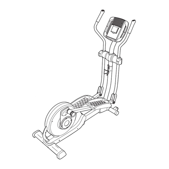
Page 30: Exploded Drawing
EXPLODED DRAWING A—Model No. EPCCEL5987.0 R1107A... - Page 31 EXPLODED DRAWING B—Model No. EPCCEL5987.0 R1107A...
-
Page 32: Ordering Replacement Parts
ORDERING REPLACEMENT PARTS To order replacement parts, please see the front cover of this manual. To help us assist you, be prepared to provide the following information when contacting us: • the model number and the serial number of the product (see the front cover of this manual) •...