Table of Contents
Advertisement
Quick Links
Installation instructions
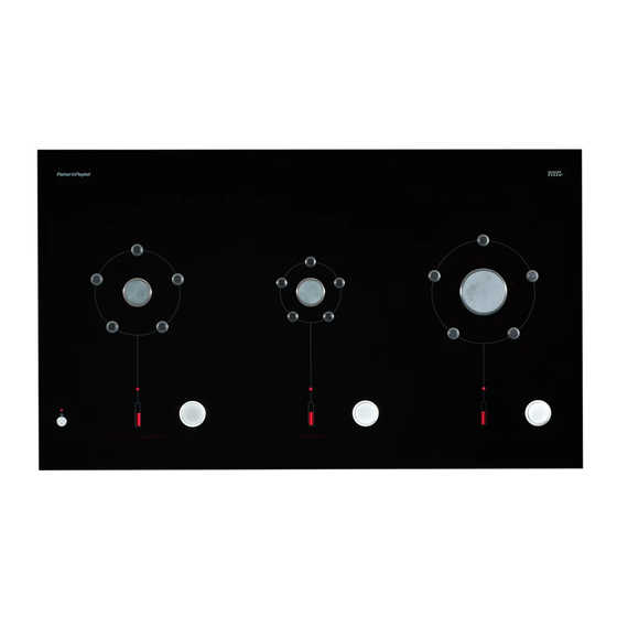
CookSurface
CG363ML and CG363MLD (DEEP) models
Important!
SAVE THESE INSTRUCTIONS
The models shown in this document may not be available in all markets and are subject to change at any time. For current details about model and specification availability in your country, please go to our
website www.fisherpaykel.com or contact your local Fisher & Paykel dealer.
1
SAFETY AND WARNINGS
Electrical shock hazard
Disconnect product from the mains power supply before servicing. This
appliance is equipped with a three-prong grounding plug for your
protection against shock hazard and should be plugged directly into a
properly grounded power outlet. Do not under any circumstances cut or
remove the grounding prong from this plug.
Failure to follow this advice may result in electrical shock or death.
Cut hazard
Take care - panel edges are sharp.
Failure to use caution could result in injury or cuts.
Important safety precautions!
This appliance shall be installed in accordance with the installation requirements of the local
gas authority or the appropriate installation code or in the absence of local codes with the latest
National Fuel Gas Code ANSI Z223.1 or CAN/CSA B149.1,2 (Canada). Local building and electrical
codes must be adhered to.
Electrical installation must be in accordance with the National Electrical Code, ANSI/NFPA70 - latest
edition or CSA C22.1 (Canada) and/or local codes.
Installation in manufactured (mobile) home: installation must conform with the Manufactured Home
Construction and Safety Standard, Title 24 CFR, Part 3280 [formerly the Federal Standard for Mobile
Home Construction and Safety, Title 24, HUD (Part 280)] or, when such standard is not applicable,
the Standard for Manufactured Home Installations, ANSI/NCSBCS A225.1, or with local codes where
applicable.
Installation in Recreational Park Trailers: installation must conform with state or other codes or, in
the absence of such codes, with the Standard for Recreational Park Trailers, ANSI A119.5.
WARNING!
WARNING!
US CA
Do not remove permanently affixed labels, warnings, or plates from the product. This may void the
warranty.
Flexible appliance connectors shall meet the requirements of ANSI Z21.24 and State Boards. They
shall not exceed 36 inches (900 mm) in length. In order to avoid hazard, these appliances must be
installed according to these instructions.
This appliance must be installed by an authorized person (Warning: this appliance must be installed
by a licensed plumber or gas fitter when within the Commonwealth of Massachusetts).
Please make this information available to the person installing the appliance as it could reduce your
installation costs.
Please leave these instructions with the appliance. Inform the customer to retain for future reference
and for the local inspectors' use.
Failure to install the appliance correctly could invalidate any warranty or liability claims.
Only genuine replacement parts may be used for servicing the appliance. These are available from
your nearest Fisher & Paykel Service Center.
Before you install the appliance, please make sure that
the local distribution conditions (nature of gas and pressure) and the adjustment of the appliance
are compatible. For adjustment conditions for this appliance, see 'Gas rate summary' under step 5 .
a suitable isolating switch is incorporated in the fixed wiring in an acceptable position.
the appliance is connected to a power outlet that is electrically grounded in accordance with local
codes or in the absence of local codes, with the National Electric Code ANSI/NFPA 70 or CSA C22.2
(Canada)
there is a power outlet (110-120V 60Hz) within reach of the appliance cable (35½ " (900 mm) from
the center rear of the appliance). This must be accessible after installation. The mains power supply
cable should not touch any metal parts
the countertop is square and level and no structural members interfere with space requirements
the countertop is made of heat-resistant material
you take note of the following recommended non-combustible materials: ¼" (6 mm) flame retardant
millboard covered with not less than No. 28 MSG sheet steel, 1⁄32" (0.4 mm) stainless steel, 1⁄32" (0.6
mm) aluminum or 1⁄32" (0.5 mm) copper
the gas shut-off valve is accessible after installation
if the power supply cable is damaged, it is replaced only by the special cable: Part no. 531954 – Flex
Terminal Block Assy US, obtainable from authorized Fisher & Paykel Service Agents.
Advertisement
Table of Contents

Related Manuals for Fisher & Paykel CG363MLDNGB1


Summary of Contents for Fisher & Paykel CG363MLDNGB1
-
Page 1: Installation Instructions
Installation instructions CookSurface US CA CG363ML and CG363MLD (DEEP) models Important! SAVE THESE INSTRUCTIONS The models shown in this document may not be available in all markets and are subject to change at any time. For current details about model and specification availability in your country, please go to our website www.fisherpaykel.com or contact your local Fisher &... - Page 2 PRODUCT & CUTOUT DIMENSIONS CLEARANCE & CABINETRY DIMENSIONS Note: Gas inlet connection is located in the back left corner. WARNING! The CookSurface requires adequate air supply to fully function. The base of the CookSurface must have direct unrestricted ventilation to the room where the CookSurface is installed.
-
Page 3: Parts Supplied
PARTS SUPPLIED Wok stand (1) Elbow 3/8 “ NPT (1) Clamping Gas pressure Air intake brackets (4) regulator (1) grill (1) and and screws (4) screws (6) IMPORTANT INSTALLATION INFORMATION We do not recommend you flush mount or seal this appliance into the counter with silicone or glue. The appliance, its individual shut-off valve and the gas pressure regulator must be disconnected Doing so will make future servicing difficult. - Page 4 FLUSH MOUNTING INSTALLATION (NOT RECOMMENDED) view from below WARNING! We do not recommend flush mounting and sealing as servicing requires the CookSurface to be removed from the countertop. The owner carries all risk for flush mounting the CookSurface. The owner must ensure the CookSurface has been cut out Refit existing from the countertop before...
- Page 5 INSTALLATION 20” (500 mm) 2” (50 mm) The CookSurface requires adequate air supply to fully function. The base of the CookSurface must have direct unrestricted ventilation to the room where the CookSurface is installed. Do not ventilate the base area to an external area that can be at different air pressure to that of the burners.
- Page 6 CHECK FOR GAS LEAKS AND TEST 4” H O NG B B B pg. 8 Test operation by lighting all burners.
-
Page 7: Final Checklist
FINAL CHECKLIST TO BE COMPLETED BY THE INSTALLER Have you installed the clamping brackets? Have you allowed for adequate air supply to the product? Have you leak-tested all connections? Is the regulator set to the correct working pressure (4” H O NG)? Have you placed the supplied duplicate data plate on an adjacent surface? Is the CookSurface grounded? - Page 8 www.fisherpaykel.com www.fisherpaykel.ca 599648C US CA 04.11...
Need help?
Do you have a question about the CG363MLDNGB1 and is the answer not in the manual?
Questions and answers