Sony DWTB01/E1424 Operating Instructions Manual
Digital wireless transmitter
Hide thumbs
Also See for DWTB01/E1424:
- Product information (82 pages) ,
- Manual (34 pages) ,
- Brochure (2 pages)

Related Manuals for Sony DWTB01/E1424


Summary of Contents for Sony DWTB01/E1424
-
Page 1: Operating Instructions
4-185-238-15 (1) Digital Wireless Transmitter Operating Instructions Before operating the unit, please read this manual thoroughly and retain it for future reference. DWT-B01 © 2010 Sony Corporation... - Page 2 For the customers in the U.S.A. - Connect the equipment into an outlet on a circuit different from that to which the Use of Sony wireless devices is regulated receiver is connected. by the Federal Communications - Consult the dealer or an experienced Commision as described in Part 74 subpart radio/TV technician for help.
- Page 3 Industry Canada technical specifications were met. For the customers in Europe Use of Sony wireless devices is regulated by the Industry Canada as described in their Before operating this unit, please read the Radio Standard Specification RSS-123.
- Page 4 Για τ υς πελάτες π υ διαμέν υν ostrożności wynikających z dyrektywy w sprawie urządzeń radiowych i σε ώρες της Ευρώπης końcowych urządzeń Πριν ρησιμ π ιήσετε αυτήν τη telekomunikacyjnych oraz wzajemnego μ νάδα, δια άστε τ ε ωριστ uznawania ich zgodności (dyrektywa έγγραφ...
-
Page 5: Table Of Contents
Table of Contents Features .......... 6 Setting the encrypted Parts Identification ......7 transmission function Power Supply ......... 9 (ENCRYPTION) ....21 Installing the batteries ..... 9 Generating an internal signal Setting the Transmission (INTERNAL SG) ....21 Channel ........10 Locking the POWER switch Selecting the group/channel ... -
Page 6: Features
The DWT-B01 transmitter covers an What is DWX? extremely wide RF carrier frequency range. DWX refers to Sony’s new digital wireless Depending on the model, the transmitter microphone system. The DWX series can cover bandwidths between 48-MHz and reflects Sony’s extensive expertise in 72-MHz (e.g., 72-MHz with the CE4248... -
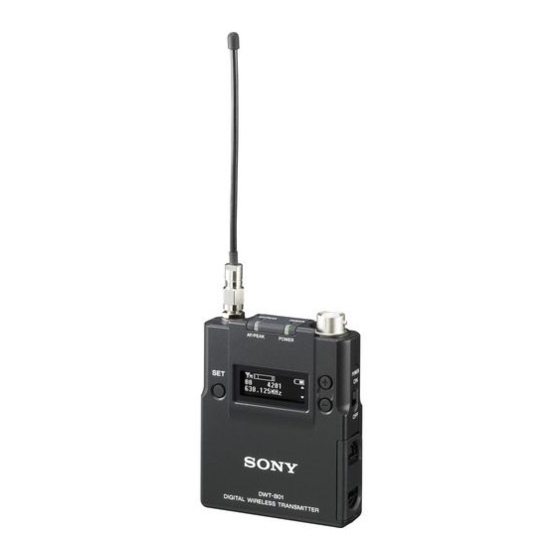
Page 7: Parts Identification
Selectable RF output power: Parts 1 mW, 10 mW, and 50 mW Identification For details, see “Setting the RF output power (RF POWER)” on page 19. Power sleep mode For details, see “Power save setting (POWER SAVE)” on page 20. Digital low-cut filter For details, see “Low-cut filter setting (LCF)”... -
Page 8: Power Switch
using key operations. By connecting the digital wireless receiver to this connector with the supplied USB cable, you can exchange the encryption key for encrypted transmission function. To connect a microphone j Display section Microphone (optional) To secure the microphone cable A RF transmission indication connection, be sure to turn and lock Indicates the current transmission status. -
Page 9: Power Supply
F POWER switch lock indicator Power Supply Indicates that the POWER switch is locked, preventing the transmitter from being accidentally turned off or on. For details, see “Locking the POWER switch The transmitter can operate on two LR6 (POWER SW LOCK)” on page 21. (size AA) alkaline batteries continuously for about 5 hours at 25°C (77°F). -
Page 10: Setting The Transmission Channel
• When BATTERY TYPE is set to Channel TYPE1, the power status is indicated based on the use of new LR6 (size AA) Sony Alkaline batteries. An incorrect indication may result when a different The transmitter provides groups of kind of batteries, a different brand of interference-free channels. -
Page 11: Selecting The Group/Channel
Set the transmitter group (GP) and channel (CH) as follows: For details, see“Pairing with a receiver” on page 12. For details on groups and channels, refer to “Sony Digital Wireless Microphone System Frequency Lists” on the supplied CD-ROM. For details on menu operation, see “Basic Menu Operations”... -
Page 12: Using The Cross Remote
To carry out pairing through menu Using the Cross operations on the transmitter, do the following. Remote Set the receiver to be used for controlling the transmitter to pairing mode. This transmitter is equipped with a wireless For details, refer to the operating instructions remote control function that can be used to supplied with the receiver. - Page 13 • Multiple transmitters cannot be paired remote control function off, then on again with the same receiver. in the RF REMOTE display, then re- • If you reset all parameters by using the pairing with the transmitter (change to a FACTORY PRESET function (see page channel with less interference).
-
Page 14: Using The Encrypted Transmission Function
The encryption key used by the transmitter Using the and receiver is newly generated for each key transmission, resulting in highly secure Encrypted communication. The encryption key used between the Transmission transmitter and the receiver is saved when the power is turned off, so the encrypted Function transmission can be resumed the next time the power is turned on. -
Page 15: Using Password Mode (Password)
Press the + or – button repeatedly to USB cable (supplied) select PASSWORD, and then press the SET button. Input a password of up to eight characters on the transmitter. To enter a password, use the procedure described in “Naming of transmitter (NAME)” on page 18. -
Page 16: Using A Usb Keyboard
Characters that can be entered from Using a USB a USB keyboard: (space), 0, 1, 2, 3, 4, 5, 6, 7, 8, 9, A, B, C, D, E, F, G, H, I, J, K, L, Keyboard M, N, O, P, Q, R, S, T, U, V, W, X, Y, Z, !, #, &, $, @, +, -, =, _, (, ), [, ] (Passwords may consist of the numbers 0 to 9 and letters A to Z only.) -
Page 17: Basic Menu Operations
• BRIGHTNESS (display brightness) Basic Menu setting • DIMMER MODE (automatic dimming Operations of the display) setting • FACTORY PRESET (factory setting) function • VERSION (software version) indication Function name Item to be set Press the + or – button repeatedly until the function to be set appears. -
Page 18: Setting Menus
The functions and parameters of the settings menu are explained here. Underlined items Match the frequency range on this are the factory setting. transmitter to that of the Sony digital wireless receiver. See “Carrier Frequencies and Channel Naming of transmitter Steps”... -
Page 19: Setting The Rf Output Power (Rf Power)
Using wireless remote control, this function • To start signal transmission with the can be controlled from the receiver and selected RF output power setting, turn off other devices. the power and then turn it on again. For details on wireless remote control function, see Using wireless remote control, this function “Using the Cross Remote”... -
Page 20: Low-Cut Filter Setting (Lcf)
120 140 160 180 200 220 (Hz): based on characteristics of new LR6 (size Low-cut filter is set according to the AA) Sony Alkaline batteries. Select this for selected frequency. LR6 (size AA) alkaline batteries. TYPE2: Select this for rechargeable Using wireless remote control, this function nickel-metal-hydride batteries. -
Page 21: Setting The Encrypted Transmission Function (Encryption)
Setting the encrypted Locking the POWER switch transmission function (POWER SW LOCK) (ENCRYPTION) The POWER switch can be locked to prevent the transmitter from being You can set the encrypted transmission accidentally turned off or on. function. Even when the POWER switch is locked, all parts of the transmitter other than the SECURE KEY: Sets the secure key POWER switch remain functional. -
Page 22: Setting The Brightness Of The Display (Brightness)
For details on how to change the transmission Notes channel, see “Setting the Transmission Channel” on • The setting for this function cannot be page 10. changed during actual signal transmission. To change the setting, turn Setting the brightness of off the power first. -
Page 23: Attaching With The Soft Case
Press down on the clasp as shown in Attaching With the illustration and slide the clip in the direction of the arrow. the Soft Case The transmitter can be attached to the user with the supplied soft case. All operations are possible when the transmitter is attached with the soft case. -
Page 24: Block Diagram
Block Diagram Attenuator Digital signal processor Head amp. Low-cut filter Audio High- A/D converter codec frequency modulator circuit Internal SG Block Diagram... -
Page 25: Troubleshooting
If you encounter a problem using this transmitter, use the following checklist to find a solution. For any problems with the receiver or adapter, refer to the operating instructions supplied with the respective device. If the problem persists, consult your Sony dealer. Symptom... - Page 26 Symptom Meanings Remedy There is too The microphone connected to Use the low-cut filter to cut the much bass. the transmitter produces bass (see page 20). excessive bass because the frequency response of the transmitter extends into the low 20-Hz range. The power The POWER switch is locked.
-
Page 27: Important Notes On Operation
It is recommended that you use the ECM- 77BC/9X Sony lavelier microphone with On cleaning this transmitter. The transmission signal may cause noise on some microphones. If • If the transmitter is used in a very humid... -
Page 28: Specifications
LINE: +24 dBu Audio attenuator adjustment range (pad) 0 to 48 dB (3dB steps, MIC input mode only) Microphone input connector Sony 4-pin (SMC9-4S) (female) Input impedance 4.7 kohms or more Frequency response 20 Hz to 22,000 Hz T.H.D 0.03% or less... - Page 29 Wireless remote control 2.4-GHz IEEE802.15.4 compliant Dimensions (unit: mm (inches)) Note Always verify that the unit is operating properly before use. SONY WILL NOT BE LIABLE FOR DAMAGES OF ANY KIND INCLUDING, BUT NOT LIMITED TO, COMPENSATION OR REIMBURSEMENT ON ACCOUNT...
-
Page 30: Carrier Frequencies And Channel Steps
Carrier Frequencies and Channel Steps Underlined items are the factory setting. US models Channel step: 25 kHz Group/channel Model No. Frequency band Frequency (factory setting) TV14-17 470.125 - 493.875 MHz U1424 TV18-21 494.125 - 517.875 MHz 00 1801 494.125 MHz TV22-25 518.125 - 541.875 MHz TV30-33... - Page 31 European models Channel step: 25 kHz Group/channel Model No. Frequency band Frequency (factory setting) TV33-35 566.025 - 590.000 MHz CE3338 TV36-37 590.025 - 606.000 MHz 00 3301 566.125 MHz TV38-40 606.025 - 630.000 MHz TV42-44 638.025 - 662.000 MHz CE4248 TV45-47 662.025 - 686.000 MHz 00 4201 638.125 MHz...
- Page 32 Sony Corporation...