Table of Contents
Advertisement
Federal regulations require ceiling fans
with light kits manufactured or imported
after January 1, 2009, to limit total
wattage consumed by the light kit to
190W.
Therefore, this fan is equipped
with a wattage limiting device.
Installation Guide
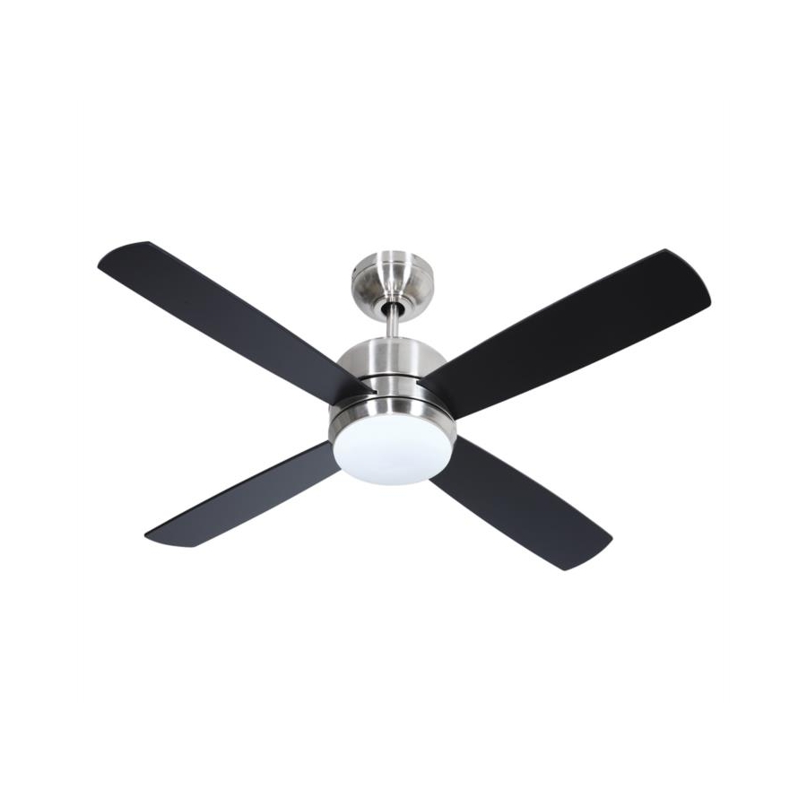
For Models:
MN44FB4
MN44SS4
E206035
net weight of fan: 13.45 lb. (6.1 kg)
READ THESE INSTRUCTIONS AND
AND SAVE THEM FOR FUTURE USE
Table of Contents:
Safety Tips. pg. 1
Unpacking Your Fan. pg. 2
Parts Inventory. pg. 2
Installation Preparation. pg. 3
Hanging Bracket Installation. pg. 3
Fan Assembly. pgs. 4 - 5
Wiring. pgs. 5 - 6
Canopy Assembly. pg. 6
Blade Assembly. pg. 7
Light Kit Assembly. pgs. 7 - 8
Wall Control Operation. pg. 9
Remote Control Operation. pg. 9
Testing Your Fan. pg. 9
Troubleshooting. pg. 10
Warranty. pg. 10
Parts Replacement. pg. 10
PRINTED IN CHINA
Advertisement
Table of Contents

Subscribe to Our Youtube Channel
Related Manuals for Craftmade MN44FB4


Summary of Contents for Craftmade MN44FB4
-
Page 1: Table Of Contents
190W. Therefore, this fan is equipped with a wattage limiting device. Installation Guide For Models: Table of Contents: MN44FB4 Safety Tips. pg. 1 MN44SS4 Unpacking Your Fan. pg. 2 Parts Inventory. pg. 2 Installation Preparation. pg. 3 Hanging Bracket Installation. pg. 3 Fan Assembly. -
Page 2: Safety Tips
SAFETY TIPS. WARNING: To reduce the risk of electrical shock, turn off the electricity to the fan at the main fuse box or circuit panel before you begin the fan installation or before servicing the fan or installing accessories. READ ALL INSTRUCTIONS AND SAFETY INFORMATION CAREFULLY BEFORE INSTALLING YOUR FAN AND SAVE THESE INSTRUCTIONS. -
Page 3: Unpacking Your Fan
1. Unpacking Your Fan. Carefully open the packaging. Remove items from Styrofoam inserts. Remove motor housing and place on carpet or Styrofoam to avoid damage to finish. Do not discard fan carton or Styrofoam inserts should this fan need to be returned for repairs. -
Page 4: Installation Preparation
3. Installation Preparation. blade edge To prevent personal injury and damage, ensure inches 7 feet (76cm) that the hanging location allows the blades a (2.13m) clearance of 7 feet (2.13m) from the floor and 30in. (76cm) from any wall or obstruction. 12 ft. -
Page 5: Fan Assembly. Pgs
5. Fan Assembly. set screw set screw hole stop pin If you wish to extend the hanging length of your fan, you must remove the hanging ball from the 6in. downrod provided to use with an extended downrod hanging ball (sold separately). -
Page 6: Wiring. Pgs
5. Fan Assembly. (cont.) wood ceiling joist safety cable loop With the hanging bracket secured to the outlet box and able to support the fan, you are now ready to hang your fan. Grab the fan firmly with two hands. Slide downrod through opening in hanging bracket and let hanging ball rest on the hanging bracket. -
Page 7: Canopy Assembly
Modifications not approved by the party responsible for compliance 6. Wiring. (cont.) could void the user's authority to operate the equipment. *NOTE: This equipment has been tested and found to comply with the limits for a Class B digital device, pursuant to Part 15 of the FCC Rules. These limits are designed to provide reasonable protection against harmful interference in a residential installation. -
Page 8: Blade Assembly
8. Blade Assembly. Loosen the screws in the 2 slotted holes in the light kit fitter (located on the underside of the motor housing) and remove the other screw. Twist light kit fitter and pull down carefully on light kit fitter in order to remove. -
Page 9: Automated Learning Process./ Activating Code
9. Light Kit Assembly. (cont.) motor housing Install the 50 watt halogen bulb, type JD E11 (included). Tip: Do not touch glass portion of bulb with fingers or hands. Oil from skin can cause bulb to overheat and go out prematurely. -
Page 10: Wall Control Operation
11. Wall Control Operation. ON/OFF slider switch - turns wall control ON or OFF HIGH button - turns fan to HIGH speed MED button - turns fan to MEDIUM speed LOW button - turns fan to LOW speed OFF button - turns fan OFF L button - turns light ON/OFF when pressed once;... -
Page 11: Troubleshooting
Return fan, shipping prepaid, to 4. Check to be sure fan is wired properly. Craftmade/Ellington. We will repair or ship you a 5. Check to be sure code switches are set properly in remote replacement fan, and we will pay the return shipping cost.
Need help?
Do you have a question about the MN44FB4 and is the answer not in the manual?
Questions and answers