Table of Contents
Advertisement
Advertisement
Table of Contents

Related Manuals for Garmin GPSMAP 215


Summary of Contents for Garmin GPSMAP 215
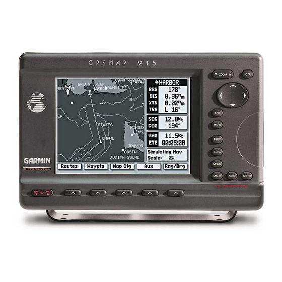
- Page 1 OWNER’S MANUAL & REFERENCE GPSMAP 215/225 ®...
-
Page 3: Foreword
GARMIN, GPSMAP 215, GPSMAP 225, AutoLocate, TracBack, MapSource, and PhaseTrac12 are all trademarks of GARMIN Corporation and may not be used without the expressed permis- sion of GARMIN. April 2000 Part Number 190-00061-20 Rev. -
Page 4: Fcc Compliance
CAUTION: The GPSMAP does not contain any user-serviceable parts. Repairs should only be made by an authorized GARMIN service center. Unauthorized repairs or modifications could void your warranty and your authority to operate this device... -
Page 5: Limited Warranty & Registration
GARMIN Corporation warrants this product to be free from defects in materials and manufacture for one year from the date of purchase. GARMIN will, at its sole option, repair or replace any components that fail in normal use. Such repairs or replacement will be made at no charge to the customer for parts or labor. -
Page 6: Packing List
This manual covers the following GPSMAP units: GPSMAP 215 3-gray level LCD chart plotter with built-in GPS (available with or without built-in DGPS beacon receiver) GPSMAP 225 color LCD chart plotter with built-in GPS... -
Page 7: Table Of Contents
PART ONE: INTRODUCTION Foreword...i Cautions...ii Limited Warranty & Registration...iii Packing List ...iv Table of Contents...v-vi Capabilities...vii Keypad Usage...viii The GPSMAP Tour ...1-13 PART TWO: REFERENCE Section 1: Satellite Status Page...15-16 Satellite and receiver status, entering initial positions Section 2: Map Page & Map Configuration...17-24 Using the target cursor, selecting zoom scales, calculating range and bearing, map configuration Section 3: Highway Page ...25-26... -
Page 8: Table Of Contents
INTRODUCTION Table of Contents Section 5: Waypoints ...28-33 Creating, editing and using waypoints; using the WAYPTS softkey Section 6: MARK Key ...34 Marking present position and target cursor position Section 7: GOTO/MOB Keys ...35-36 Going to a destination and using man overboard function Section 8: Routes...37-45 Creating, activating and modifying routes;... -
Page 9: Capabilities
Designed for detailed electronic charting and simple operation, the GARMIN GPSMAP system is a powerful navigation device that can help guide you in waterways around the world: Precision Performance • 16-color active-matrix TFT screen (GPSMAP 225) • 3-Gray FTN LCD screen (GPSMAP 215) •... -
Page 10: Keypad Usage
INTRODUCTION Keypad Usage The GPSMAP system uses a set of on-screen ‘softkeys’ to perform route, waypoint and setup functions. These softkeys allow you to perform many navigation functions and custom setups right from the map display. viii The ZOOM key changes the map display scale to one of 16 avail- able settings, or the highway display scale to one of five settings. -
Page 11: The Gpsmap Tour
The GARMIN GPSMAP is a powerful electronic charting/navigating system that provides detailed chart coverage and convenient control of many advanced features right from the graphic charting page. This tour is designed to take you through the basic pages and functions of the GPSMAP system. - Page 12 GPSMAP TOUR Simulator Setup The GPSMAP system does not actively track satellites in the simulator mode. Never use the simulator mode for actual navigation. Any waypoints, routes and track logs you create while simulating navigation will be saved in memory, and are available for use when using the unit in normal operating mode.
- Page 13 Now that you are back at the Satellite Status Page, let’ s enter a starting posi- tion for our tour. Entering names and numbers in the GPSMAP system is done through data entry windows. Once a data entry window is open, the keypad and key are used to choose and accept a value for each character position:...
- Page 14 GPSMAP TOUR Map Page The Data Window (at the right side of the screen) and the Softkey Menu Display (at the bottom of the screen) may be turned off for a full page display of cartography: • To turn the Data Window off, press •...
- Page 15 The destination field, located at the top of the data window, shows your bearing (BRG) and distance (DIS) to a destination waypoint or to the cursor. It also displays your crosstrack error (XTK) and turn (TRN) heading to an active destination.
- Page 16 GPSMAP TOUR Using the Target Cursor As you move the cursor, the distance and bearing from your present position to the cursor will be displayed in the destination field (at the top right of the screen). The cursor’s position coordinates will be dis- played in the position field (below the speed and course field).
-
Page 17: Marking A Position
To continue the tour, let’ s mark our simulated present position for reference: 1. Press the key to capture your present position as a waypoint. The Mark GPS Position window will appear, with a default three-digit waypoint name and symbol. By pressing the waypoint with the default name and symbol, but let’... - Page 18 GPSMAP TOUR Creating a Route Whenever the cursor comes in close proximity to an on-screen waypoint or navaid, it will ‘snap’ to and highlight its on-screen icon. Once an on-screen marker has been high- lighted, destination and position information will be displayed in the data window. This feature makes it easy to review waypoint positions right from the map display.
- Page 19 Now add the final waypoint to the route: 1. Use the keypad to move the arrow cursor as close as possible to the following coordinates: N24º21.777’, W077º51.424. 2. Press the key to save the waypoint position. 3. Press to confirm the default waypoint name, symbol and comment. We now have a three waypoint route from our present position to waypoint 002.
- Page 20 GPSMAP TOUR Navigating a Route The Simulator SOG/COG window lets you specify the speed and course for the simulator mode. By leaving the COG field value at the default setting, the GPSMAP system will automatically set a course directly to your destination.
- Page 21 You are now underway toward the first waypoint in your route. Whenever there is an active route in use for navigation, the GPSMAP will display route waypoint and leg information on the Active Route Page. To view the Active Route Page from the Highway Page: 1.
- Page 22 GPSMAP TOUR Marking a GOTO Destination As you approach a destination waypoint, an audible alert and on-screen message will indicate when you are one minute from your destination. To acknowledge the message: 1. Press the key. Whenever you’re finished navigating a route with the GPSMAP system, you’ll need to clear the Active Route to stop navigation guidance to the last route waypoint.
- Page 23 Congratulations! You’ve now gone through the basic operation of the GARMIN GPSMAP system. Your new unit is a powerful navigation device with many advanced features not covered in the tour. Now that you have a working knowledge of the unit, use the reference section of this manual to help you with advanced navigation and setup functions.
-
Page 24: Reference Section
REFERENCE SECTION 1 – SATELLITE STATUS PAGE 2 – MAP PAGE 3 – HIGHWAY PAGE 4 – ACTIVE ROUTE PAGE 5 – WAYPOINTS 6 – MARK KEY 7 – GOTO/MOB 8 – ROUTES 9 – AUXILIARY MENU 10 – G-CHART CARTRIDGES... -
Page 25: Section 1: Satellite Status Page
Signal Strength Indicators The GPSMAP 215/225 Satellite Status Page provides a visual reference of various receiver functions, including current satellite coverage, receiver operating mode and present position or DGPS status. The status information will give you an idea of what the receiver is doing at any given moment. - Page 26 (SNR), and the distance from your beacon receiver to the DGPS transmitter.( If available) GPSMAP 215/225 units purchased without the internal beacon receiver can be upgraded to DGPS accuracies using the GARMIN GBR 21 or GBR 23 beacon receiver.
-
Page 27: Section 2: Map Page & Map Configuration
Display Boat Icon The GPSMAP Map Page provides a comprehensive display of electronic cartography, plotting and navigational data. It is the primary page used for navigating with the GPSMAP system. The Map Page can be broken down into three main sections: map display, data window and softkey menu. The map display shows your boat on an electronically generated chart, complete with geographic names, navaids, depth contours and a host of other chart features. - Page 28 SECTION MAP PAGE Map Page Modes Boat Mode Cursor Mode The map display uses the cursor keypad and a set of hard keys to control most map display functions. The with the keypad lets you select zoom ranges, move the cursor and display chart outlines.
- Page 29 The cursor allows you to pan away from your present position and scroll to other map areas around the world (even outside of your current G-chart coverage). As you pan past the edge of the current map display, the screen will actively scroll forward to provide continuous map coverage wherever you move the cursor.
- Page 30 SECTION MAP PAGE Selecting Zoom Scales Overzoom Mode Track Plot Mode The map display has 16 available range scales from 1/8th to 4096 n.m. (1/4 to 7500km). The map scale is controlled by the scale displayed at the bottom of the data window. To select a map scale: 1.
- Page 31 The second section of the Map Page is the data window, located at the right side of the screen display. The data window provides a digital display of navigation data in relation to your present position, the cursor position or a particular waypoint.
- Page 32 SECTION MAP PAGE Range & Bearing Softkey Menu Calculating Range/Bearing Expanded Map Display The last section of the Map Page is the softkey menu, which is displayed across the bottom of the screen. The first two softkeys provide quick access to route and waypoint functions from any GPSMAP page.
- Page 33 The GARMIN GPSMAP system features a graphic map display with 16 zoom scales from 1/8th to 4096 n.m. (1/4 to 7500km). By using G-chart and offshore chart cartridges, the map display can show a wide variety of chart details such as depth contours, shorelines, marinas and navigation aids.
- Page 34 SECTION MAP CONFIGURATION Map Calibrations WARNING! The map calibration function is valid only in a limited range. The further you are away from the point of correction, the larger the position error will be. Keep in mind that Selective Availability can cause position errors up to 330 feet (100 m).
-
Page 35: Section 3: Highway
Active Destination Highway Display ETE & ETA Fields Remove Waypoint Name Markers Softkey The GPSMAP Highway Page provides a large character display of navigation data and graphic steering guidance to an active waypoint via a highway display. The active destination waypoint is displayed at the top of the screen, with the ETE (estimated time enroute) and ETA (estimated time of arrival) based on your present speed and course at the bottom. - Page 36 SECTION HIGHWAY PAGE Highway Display & Scale The bearing pointer, directly below the high- way display, always points to the destination waypoint (or the next waypoint when using a route) relative to your course over ground (COG). If the bearing pointer points straight ahead, you are heading directly to your destination.
-
Page 37: Section 4: Active Route Page
The last page in the main sequence is the Active Route Page. The Active Route Page shows each waypoint of the active route (in order), with the waypoint name, desired track, cumulative distance and ETE or ETA for each waypoint from the present position. Your current destination waypoint, the ‘active to’... -
Page 38: Section 5: Waypoints
SECTION Creating Waypoints Graphically The GARMIN GPSMAP system stores over 1900 alphanumeric waypoints with a user-defined icon and comment available for each waypoint. Waypoints can be created, reviewed, moved or deleted right from the Map Page using the target cursor to select positions and waypoints, and are managed through the WAYPOINTS softkey. - Page 39 Other graphic waypoint functions include reviewing and modifying on-screen waypoints. By moving the cursor close to an on-screen waypoint, you can “snap” to a specific waypoint. Once the target cursor snaps to a waypoint, the waypoint will be highlighted with a white circle, and the GPSMAP will display waypoint information in the data window at the bottom right corner of the screen.
- Page 40 SECTION WAYPOINTS Moving & Deleting Waypoints Graphically The last two graphic waypoint functions allow you to move a highlighted on-screen waypoint or delete it from system memory using the map display. To move an on-screen waypoint: 1. Use the keypad to ‘snap to’ the on-screen waypoint. 2.
- Page 41 To scroll through and review the waypoint list: 1. Press the WAYPTS softkey (if you are not currently in the waypoints submenu). 2. Press the LIST softkey. 3. Use the keypad to scroll through the list in either direction. 4. Press the key to review the highlighted waypoint.
- Page 42 SECTION WAYPOINTS Creating Waypoints by Text Entry The CREATE softkey lets you create new waypoints by entering a name and position, or by entering the distance and bearing from an existing (reference) waypoint. To create a new waypoint from the list submenu: 1.
-
Page 43: Section 5: Waypoints
To create a new waypoint using a reference waypoint: 1. Follow steps 1-5 (on page 32) for creating a new waypoint. 2. Highlight the reference waypoint field and press the SCAN softkey. 3. Use the keypad to scan the waypoint list and find the desired reference waypoint. -
Page 44: Section 6: Mark Key
MARK KEY Marking GPS & Cursor Positions The GARMIN GPSMAP system features a capture your present position or a target cursor position and create a new waypoint right from the map display. The position when the cursor is not in use, or will give you the option of marking your present position or the cursor position when the cursor is in use. - Page 45 The GPSMAP’ s GOTO command lets you select any stored waypoint or target cursor position as a destination and quickly set a course from your present position. Once a GOTO has been activated, the Highway Page will provide steering guidance to your destination. A GOTO may be activated on the map display using the cursor, or from any waypoint list.
-
Page 46: Section 7: Goto/Mob Keys
SECTION GOTO/MOB Stopping Active GOTOs MOB Function Once a GOTO has been activated, the GPSMAP will keep the waypoint as your active destination and provide steering guidance until you stop the active GOTO. To stop navigating to an active GOTO position: 1. -
Page 47: Section 8: Routes
The GARMIN GPSMAP system lets you create and store up to 20 reversible routes with up to 50 waypoints each. Routes can be created and modified right from the Map Page, allowing you to see each route graphically on-screen as you create, review, modify or navigate the route. -
Page 48: Routes Softkey
SECTION ROUTES Creating Routes Graphically All of the GPSMAP route functions are accessed through the ROUTES softkey, located at the far left of the softkey menu. To create a route from the map display: 1. Press the ROUTES softkey to display the route list window. 2. -
Page 49: Routes Softkey
When the review mode is in use, the cursor may be used to highlight indi- vidual route legs. When a route leg is highlighted, the ‘active from’ and ‘active to’ waypoints will be displayed at the bottom of the data window, with the desired track (DTK) and distance (DIS) for the leg indicated below. - Page 50 ROUTES SECTION Modifying Routes Moving Route Waypoints The next softkey in the route review mode allows you to modify a route by moving, inserting or removing route waypoints on screen or editing a route through a text review window. To modify the on-screen route: 1.
- Page 51 The INSERT softkey allows you to add a waypoint before the first route waypoint or after the last route waypoint; or add a new route waypoint to an existing route leg. To insert a new starting or ending route waypoint: 1.
- Page 52 SECTION ROUTES Removing Waypoints Route Comments To remove a route waypoint: 1. Use the keypad to snap to and highlight the waypoint you want to remove. 2. Press the REMOVE softkey. The ENT TEXT softkey will display a text editing window where you may add a route comment, insert or delete waypoints or review any waypoint of the on-screen route.
- Page 53 The Edit Route window will also let you scroll through the list of route waypoints, review each waypoint, and change waypoint information. To review a route waypoint: 1. Select the Edit Route window using either method described on page 42. 2.
- Page 54 SECTION ROUTES Editing Routes by Text From the Select Route Waypoint window, you can also determine the distance and bearing between the route waypoint shown and any other waypoint in memory. To use the reference waypoint function: • Highlight the ‘Ref Wpt’ field •...
-
Page 55: Section 8: Routes
In addition to the graphic on-screen creation of routes, the GPSMAP system also provides a data entry window for creating new routes. To create a route through data entry: 1. Press the ROUTES softkey to display the route list window. 2. -
Page 56: Auxiliary Menu
SECTION AUXILIARY MENU Menu Options The GPSMAP’ s AUX softkey provides access to the various system, naviga- tion and interface setup menus used to customize your unit’ s operation. Once you have pressed the AUX softkey, you’ll see a complete list of available options listed by category. - Page 57 When an Auxiliary Menu option is selected and displayed, you’ll see a complete listing of available functions, with the current setting for each option indicated. Once you’ve entered a submenu, you’ll use one of two data entry formats to enter most of your setup preferences: The option window provides you with a list of menu choices from which you select your preferences.
- Page 58 SECTION AUXILIARY MENU System Setup Options The system setup submenu is used to select the operating mode, date and time formats, tone preferences and display contrast. Operational Mode lets you select between normal operation and simulator mode. The GPSMAP system does not track satellites in simulator mode, and should not be used for actual navigation.
- Page 59 The navigation setup submenu is used to select a variety of navigation infor- mation, including position format, units of measure, and heading preferences. This submenu is also used to select map datums and map display orientation. Position Format lets you select the coordinate system used to display position.
- Page 60 SECTION AUXILIARY MENU Navigation Setup & Map Settings The navigation setup submenu is also used to select map datums and adjust the built-in position and velocity filters. The GPSMAP system’ s default map datum is WGS 84, a worldwide map datum that’ s suitable for use with most government charts.
-
Page 61: Auxiliary Menu
SECTION The timer/alarm setup submenu is used to control the GPSMAP’ s various AUXILIARY MENU alarm and timer settings. Timer/Alarm Setup Count Down timer controls an alarm to sound when an entered interval (up to 99:59:59) has expired. Enter a time interval in the time field and use the control field to the immediate right to run, stop or reset the timer. - Page 62 SECTION AUXILIARY MENU Interface Settings Interface Formats External DGPS unit shown. External DGPS unit shown. The GPSMAP interface setup submenu provides interface settings for con- necting external NMEA electronic devices, a PC and/or a differential GPS (DGPS) beacon receiver. The settings, listed at the top of the interface setup window, control a bi-directional I/O port with six (built in DGPS) or nine (optional, external DGPS) available interface formats: Data Transfer is a proprietary interface that allows you to exchange data such...
- Page 63 When using an external beacon receiver, three additional formats are provided to accept RTCM input corrections: GARMIN DGPS (external DGPS only)used for connecting your GPSMAP unit with a GARMIN DGPS receiver. RTCM In/NMEA Out (external DGPS only) provides an input interface for connection of a DGPS beacon receiver and a selectable NMEA output to control tuning functions.
- Page 64 To have the unit automatically scan for a frequency: 1. With the unit set to ‘Garmin DGPS’ or ‘RTCM In/NMEA Out’, use the key to highlight the “Tuning Mode” field and press 2. Highlight ‘Scan’ and press .
- Page 65 The “Bcn Rcvr” field on the Status Page will show one of the following: • Tuning— unit is attempting to tune to the specified frequency and bit rate. • Scanning— unit is automatically scanning through the frequencies and bit rates. •...
- Page 66 SECTION AUXILIARY MENU Proximity Waypoints List If a proximity alarm circle overlaps with an existing alarm circle, a ‘proximity overlap’ warning will be displayed. As long as the over- lap exists, the overlap warning will be dis- played each time the GPSMAP is turned on. If you enter an alarm circle overlap, the GPSMAP will only inform you of the closest proximity waypoint.
- Page 67 The GPSMAP system features a route planning window that will calculate and display the desired track and distance to route waypoints, along with the total fuel required and estimated time enroute (ETE). To use the route planning mode: 1. Highlight the Route Trip Planning option from the Auxiliary Options window and press the key.
- Page 68 SECTION AUXILIARY MENU Point-to-Point Planning Sunrise/Sunset Planning The GPSMAP’ s point-to-point planning feature lets you calculate the desired track, trip distance, fuel usage, ETE and ETA between any two waypoints or your present position and a stored waypoint. The planning mode will also pro- vide sunrise and sunset data at your destination on the specified arrival date.
- Page 69 The GPSMAP’ s track recording submenu lets you specify whether or not to record a track plot (an electronic recording of your path) and define how it is recorded. It also provides an indicator of the track memory used, and functions to clear the track memory or create a TracBack route.
-
Page 70: Auxiliary Menu
AUXILIARY MENU SECTION Track Recording TracBack Start TracBack allows you to retrace your path using the track plot automatically stored in the receiver’s memory. This eliminates the need to manually store way- points along the way. A track plot is an electronic breadcrumb trail, showing the path you have travelled. - Page 71 The last listing on the auxiliary options menu is the glossary function. The GPSMAP’ s on-screen glossary contains basic information on general navigation terms and abbreviations, as well as helpful hints on using your unit. To use the on-screen glossary: 1.
-
Page 72: Section 10: Using G-Chart Cartridges
Cartridges Cartridge Door Latch Ring The GARMIN GPSMAP system uses G-chart™ digital cartography to display nautical charts on-screen. G-chart™ inland and offshore cartridges are installed in the card slot located at the bottom right of the GPSMAP unit. G-chart™ car- tridges may be installed or removed at any time, whether the unit is on or off. - Page 73 Once a G-chart cartridge has been inserted, the map coverage outlines for the cartridge will automatically appear on screen. Keep in mind that the display will not automatically scroll to the map area or zoom to a level where you can see the coverage outlines.
-
Page 74: To View Port Services Information
SECTION G-CHART CARTRIDGES Port Services Information Port Services Information Icons Some G-chart™ cartridges include port services information, which lists available services and facilities for the selected area. When this information is available, a port services ‘information’ icon will appear on the map display (typically at lower scale settings only). -
Page 75: Appendix A: Installation
Cigarette Lighter Adapter Reading through the entire installation section before starting your installation will help you get the most out of your GARMIN navigation system. An improper or poorly planned installation can affect the GPS receiver’s accuracy, overall performance and your ability to satisfactorily use the GPSMAP system. -
Page 76: Mounting The Antenna(S)
For proper operation, the ground strap must be connected to a vessel (earth) ground. Do not ground the coupler to the electrical system. GARMIN antennas screw directly onto any standard 1” x 14 thread antenna mount. If you need to raise an antenna to avoid shading, try using a 1” x 14 thread extension mast available at most marine dealers. - Page 77 BNC connector on the back of the unit. DGPS capability can be added, as an option, by purchasing an external beacon receiver—such as GARMIN’ s GBR 21/23. Connections to an external beacon receiver are made using the NMEA IN, NMEA OUT (for GBR 21/23 only) and GROUND connections on the supplied power/data cable.
- Page 78 Mounting the GPSMAP unit The GARMIN GPSMAP’ s fully gasketed and sealed case is suitable for mount- ing in exposed locations or at the nav station. The unit comes with a gimbal bracket that can be used for surface or overhead mounting. When choosing a location for the display unit, make sure you consider the following conditions: •...
-
Page 79: Connecting The Power/Data Cable
Connecting the power/data cable The power/data cable connects the GPSMAP system to a 10-40 volt DC power source and provides interface capabilities for connecting NMEA devices, an external beacon receiver (if not equipped with built-in DGPS), and an external alarm (see section 9 for interface operation details). The color code in the diagram below indicates the appropriate harness connections. -
Page 80: Appendix B: Wiring Installation / Nmea Formats
PGRMZ (altitude), PSLIB (beacon receiver control input) DGPS corrections are accepted in RTCM-104 v. 2.0 format through the NMEA in (BROWN) harness lead. The GARMIN GBR 21 or GBR 23 are the recommended beacon receivers for use with the GPSMAP system.Other... -
Page 81: Appendix C: Physical Specifications
0.1 knot RMS steady state Dynamics: 6g’s POWER Input: 10-40vDC Usage: 15 watts max. / 9 watts typical (215) 25 watts max. / 13 watts typical (225) APPENDIX SECTION Physical Specifications Specifications subject to change without notice. * With built-in DGPS beacon receiver or external GARMIN GBR 21 or GBR 23 Beacon Receiver Input. -
Page 82: Appendix D: Messages
Display ROM Failed—The graphic processor read-only memory has failed and the unit is no longer operable. See an authorized GARMIN service center for repair. Max Calibration Is 5000mt (16,400 ft)—You have exceeded the maximum possi-... - Page 83 (when the unit is off) needs to be replaced. Take your unit to an authorized GARMIN service center for installation of a new battery. No DGPS Position—Not enough data is being received to compute a DGPS position or unit has lost DGPS signal.
- Page 84 SECTION Received Invalid Waypoint—A waypoint was received during upload transfer that APPENDIX has an invalid identifier. Messages Receiver Failed—A failure in receiver hardware has been detected. If this message persists, do not use the unit and take it to an authorized dealer for repair. Route is Full—You have attempted to add more than 50 waypoints to a route.
-
Page 85: Appendix E: Time Offsets
The chart below gives an approximate UTC(Universal Time Coordinate) time offset for the various longitudinal zones. Check with local charts for more detailed informa- tion. If you are in daylight savings time, add one hour to the offset. Longitudinal Zone W180.0º... -
Page 86: Appendix F: Map Datums
SECTION APPENDIX Map Datums The GPSMAP’s built-in world-wide database includes chart coverage down to 64 n.m. (120 km) for the areas outlined above. Note that the GPSMAP database is only valid to 68º15’ of latitude. The maximum cursor latitude is 85º05’, and the maximum waypoint latitude is 89º24.543 north or south. -
Page 87: Map Datums
Cape Cape- South Africa Indian Thailand Cape Canavrl Cape Canaveral- Florida, Indonesia 74 Bahama Islands Ireland 1965 Carthage Carthage- Tunisia ISTS 073 Astro CH-1903 CH 1903- Switzerland Chatham 1971 Chatham 1971- Chatham Johnston Island Island (New Zealand) Kandawala Chua Astro Chua Astro- Paraguay Kerguelen Islnd Corrego Alegr... -
Page 88: Appendix F: Map Datums
SECTION APPENDIX Map Datums Central America (Belize, Costa Rica, El Salvador, Prov S Chln ‘63 Guatemala, Honduras, Nicaragua) Puerto Rico NAD27 CONUS North Am. 1927- Mean Qatar National Value (CONUS) Qornoq NAD27 Cuba North American 1927- Reunion Cuba Rome 1940 NAD27 Grnland North American 1927- RT 90... -
Page 89: Appendix G: Glossary
SECTION Almanac Data—Satellite constellation information (including location and health of APPENDIX satellites) that is transmitted to your receiver from every GPS satellite. Almanac data must be acquired before GPS navigation can begin. Glossary Bearing—The compass direction from your position to a destination. Course Over Ground (COG)—Direction of movement relative to a ground position. - Page 90 SECTION APPENDIX Glossary Turn (TRN)— The difference and direction in degrees between the bearing to your destination and your course over ground. The TRN value is used to indicate what direction and how many degrees to turn to get back on course. Universal Time Coordinated (UTC)—...
-
Page 91: Appendix H: Loran Tds
SECTION APPENDIX Loran TD System LORAN C is a radio navigation aid operated and maintained in the United States Loran TDs by the United States Coast Guard. The name LORAN is an acronym for "LOng RAnge Navigation". The LORAN system covers the entire United States and the U.S. - Page 92 SECTION APPENDIX Loran TDs information will reflect those changes. Since the GPSMAP unit does not rely on the LORAN signal for navigation, it can reference a different GRI chain and/or secondary stations and still navigate to the location stored in memory. The LORAN Position Format field is located in the Navigation Setup Menu.
-
Page 93: Index
Cross Track Error ...79 Activating Routes...39 CTR Key ...viii, 6, 19 Active Route ...11, 27, 37 Cursor Mode ...18 Active Route Page ...11, 27 Cursor Movement...6, 19 Active Waypoints ...25, 27, 37 Alarm Setup...51 Anchor Alarm...51 Data Entry ...3, 47 Antenna Installation ...66-67 DATA Key ...viii, 4, 10-11, 22, 25 Arrival Alarm...51... - Page 94 INDEX Map Datum Selection ...50 G-chart Cartridges...62-64 Map Display ...4 Glossary ...59, 79-80 Map Orientation ...50 GOTO Key ...viii, 12, 35-36 Map Page...17-24 Grid Coordinates...49 Map Scales...20 Ground Speed...79 MAPS Key...viii, 11, 63 Marine Data...23 MARK Key...viii, 7, 34 Heading Selection...49 Marking Positions...7, 34 Highway Page...25-26 MENU Key ...viii, 4, 22...
- Page 95 Sky View (Satellite)...15 Softkeys...2 Softkey Menu ...5, 22 Packing List ...iv Satellite Status Page ...2, 15-16 PAGE Key ...viii Sunrise/Sunset Calculation ...58 Physical Specifications ...71 Point-to-Point Planning ...58 Port Services Information ...64 Target Cursor ...6, 18 Position Entry...3, 16 Text Entry ...3, 47 Position Format ...49 Time Offsets ...48, 75 Power/Data Cable ...69...
- Page 98 © 1998-2000 GARMIN Corporation 1200 E. 151st Street, Olathe, KS 66062 U.S.A. Web Site Address: www.garmin.com GARMIN (Europe) Ltd., Unit 5, The Quadrangle, Abbey Park, Romsey, Hampshire SO51 9AQ U.K. Garmin (Asia) Corp., No. 68, Jangshu 2 Rd., Shijr, Taipei County, Taiwan...
Need help?
Do you have a question about the GPSMAP 215 and is the answer not in the manual?
Questions and answers