Advertisement
273 Branchport Avenue
Long Branch, NJ 07740
(800) 631-2148
www.cooperwheelock.com
Use this product according to this instruction manual. Please keep this instruction manual for future reference.
GENERAL:
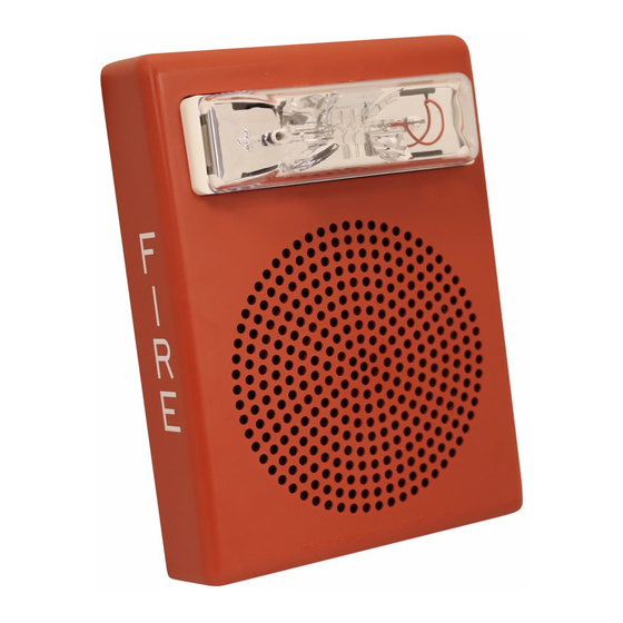
The E50 Multi-Candela Speaker Strobes are UL Listed under Standard 1971 for Signaling Devices for the Hearing Impaired and UL Standard 1480 for Speaker
Appliances. The E50A Multi-Candela Speaker Strobe with amber lens is not UL approved. They are designed for multiple power requirements with high dBA output
at each power tap. All models offer a choice of field selectable taps, 1/8W to 2W, for either 25.0VRMS or 70.0VRMS audio systems. The design incorporates a high
efficiency speaker for maximum output at minimum power across a frequency range of 400Hz to 4000Hz, and features a sealed back construction for extra protection
and improved audibility. The Speaker Strobes can provide non-synchronized strobe operation when connected directly to a Fire Alarm Control Panel (FACP), or
provide synchronized strobe operation when used in conjunction with a Sync Module (SM), Dual Sync Module (DSM), or Wheelock's Power Supplies, PS-12/24-8MP
and PS-12/24-8CP. The E50-24MCW provides four selectable candela settings (15,30,75, & 110cd), and the E50-24MCWH provides two selectable settings (135 &
185cd). All models are UL Listed for indoor use only and wall mounting only with the backboxes specified in these instructions (see Mounting Options).
NOTE: All CAUTIONS and WARNINGS are identified by the symbol
CAUTION: The speaker strobe appliance is a fire alarm device. Do not paint
WARNING:
PLEASE READ THESE INSTRUCTIONS CAREFULLY.
INSTRUCTIONS, CAUTIONS AND WARNINGS COULD RESULT IN IMPROPER APPLICATION, INSTALLATION AND/OR OPERATION OF
THESE PRODUCTS IN AN EMERGENCY SITUATION, WHICH COULD RESULT IN PROPERTY DAMAGE AND SERIOUS INJURY OR DEATH TO
YOU AND/OR OTHERS.
SPECIFICATIONS:
Model
Voltage
(VRMS)
E50-24MCW
25/70
E50-24MCWH
25/70
NOTES:
1.
Strobes will produce 1 flash per second over the "Regulated Voltage" range.
2.
All models are UL Listed for indoor use with a temperature range of +32ºF to +120ºF (0ºC to +49ºC) and maximum humidity of 85% RH.
3.
dBA is rated per UL Standard 1480 for Speaker Appliances. Frequency range of speakers is 400-4000Hz.
4.
For UL applications these appliances were tested to the operating voltage limits of 16-33 volts using Filtered (DC) or unfiltered Full-Wave-Rectified (FWR).
Do not apply 80% and 110% of these voltage values for system operation.
5.
Check the minimum and maximum output of the power supply and standby battery and subtract the voltage drop from the circuit wiring resistance to
determine the applied voltage to the strobes.
6.
Strobes with clear meet the required light distribution patterns defined in UL1971.
7.
Candela ratings are for clear lens. Strobes with amber lens have 75% of the light output of clear lens.
DC
FWR
NOTE: Candela setting will determine the current draw of the product.
NOTE: The maximum wire impendence between strobes shall not exceed 35 OHMS. The maximum number of strobes on a single notification appliance circuit shall
not exceed 47.
CAUTION: Speaker Strobes are not designed to be used on coded systems in which the applied voltage is cycled on and off.
NOTE: Make sure that the total RMS current required by all appliances that are connected to the system's primary and secondary power sources, NAC Circuits, SM,
DSM, SYNC Modules or Wheelock Power Supplies do not exceed the power sources' rated capacity or the current ratings of any fuses on the circuits to which these
appliances are wired.
WARNING: OVERLOADING POWER SOURCES OR EXCEEDING FUSE RATINGS COULD RESULT IN LOSS OF POWER AND FAILURE TO
ALERT OCCUPANTS DURING AN EMERGENCY.
Copyright 2007 Cooper Wheelock. All rights reserved
Thank you for using our products.
INSTALLATION INSTRUCTIONS
E50 MULTI-CANDELA SPEAKER STROBES
Table 1: UL Listed Models and Ratings
Speaker
dBA at 10 Feet
(Rated Watts)
1/8
1/4
1/2
77.0
79.5
82.5
77.0
79.5
82.5
Table 2: UL Current Rating for Strobe Only
Maximum RMS Current (AMPS)
UL
Voltage
15cd
16-33VDC
0.060
16-33VRMS
0.102
. All warnings are printed in bold capital letters.
FAILURE TO COMPLY WITH ANY OF THE FOLLOWING
Regulated
Voltage
1
2
(VDC/VRMS)
85.0
88.0
24
85.0
88.0
24
24MCW
30cd
75cd
0.092
0.165
0.155
0.253
Strobe
Voltage
Range
(VDC/VRMS)
16-33.0
15/30/75/110
16-33.0
24MCWH
110cd
135cd
185cd
0.220
0.300
0.420
0.347
0.455
0.645
Candela
Mounting
(cd)
Options
A,B
135/185
A,B
P84579 H
1
Sheet
of 6
Advertisement
Table of Contents

Subscribe to Our Youtube Channel
Related Manuals for Wheelock Cooper E50-24MCW


Summary of Contents for Wheelock Cooper E50-24MCW
- Page 1 NOTE: Make sure that the total RMS current required by all appliances that are connected to the system’s primary and secondary power sources, NAC Circuits, SM, DSM, SYNC Modules or Wheelock Power Supplies do not exceed the power sources’ rated capacity or the current ratings of any fuses on the circuits to which these appliances are wired.
- Page 2 When calculating the total currents, use Table 2 to determine the highest value of “RMS Current” for an individual strobe (across the expected operating voltage range of the strobe), then multiply these values by the total number of strobes; be sure to add the currents for any other appliances, including audible signaling appliances, powered by the same source and include any required safety factors.
- Page 3 (OPTIONAL) the appliances. * Refer to Sync Module instruction sheets SM (P83123), DSM (P83177) or Wheelock’s Power Supplies for additional information. GROUNDING: Connect ground wire to backbox. Install signaling appliance to backbox using mounting screws provided. NOTE: Check electrical ratings specified in tables 1 and 2 (as appropriate) to ensure proper electrical input. Be sure that speaker wiring is connected to speaker terminals only and strobe wiring is connected to strobe terminals only.
- Page 4 Although the limits shown for each mounting option comply with the National Electrical Code (NEC), Cooper Wheelock recommends use of the largest backbox option shown and the use of approved stranded field wires, whenever possible, to provide additional wiring room for easy installation and minimum stress on the product from wiring.
- Page 5 NOTE: Surface backbox (E50SSB) in Figure B, is compatible with wiremold and conduit. Mounting holes are for single-gang, double-gang, and #10 wood screws for stud mounting. If metal conduit is installed onto top and bottom conduit entrances, then an insulated grounding wire (18 AWG, supplied) must be connected between the top and bottom plate by using thread cutting screws (supplied) to provide electrical continuity per UL 50.
- Page 6 Cooper Wheelock, Inc.'s liability on any claim of any kind shall cease immediately upon the installation in the product of any part not furnished by Cooper Wheelock, Inc. In no event shall Cooper Wheelock, Inc. be liable for any claim of any kind unless it is proven that our product was a direct cause of such claim.
Need help?
Do you have a question about the Cooper E50-24MCW and is the answer not in the manual?
Questions and answers