Table of Contents
Advertisement
Advertisement
Table of Contents

Related Manuals for Electrolux Wascator W100


Summary of Contents for Electrolux Wascator W100
-
Page 1: Service Manual
SERVICE MANUAL W75 – W100 – W160 – W230 471 1553-51... - Page 3 NOTICE TO SERVICE PERSONNEL INSTALLATION Improper installation of Wascomat laundry and wet cleaning equipment can result in personal injury and severe damage to the machine. REFER INSTALLATION TO QUALIFIED PERSONNEL! RISK OF ELECTRIC SHOCK The equipment utilizes high Voltages. Disconnect electric power before servicing. The use of proper service tools and techniques, and the use of proper repair procedures, is essential to the safety of service personnel and equipment users.
-
Page 4: Table Of Contents
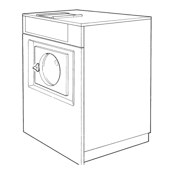
Machine description – Safety regulations Data Description of principle components Summary Programmes Periodic maintenance Service- instruc- Function sequences – Fault finding tions Automatic unit Timer Level control Thermostat Included Door and safety locking device units and Motor components Inlet valve, water Drain valve Heating Coin meter... - Page 6 Service 9112 Manual 1. Machine description Type Edition Page Fig. The 70 100, 160 and 230 litre washing machines described in this manual are normal spin machines and differ only in size and washing capacity. The machines are intended for installation in apartment houses, hotels, laundries, industries, hospitals, smaller institutions and other regular users who require machines with high reliability, large washing capacity and easy maintenance.
- Page 7 Service 9112 1. Machine description Manual Type Edition Page Safety Regulations • The machine is designed for water washing only. • The machine must not be used by children. • Installation and service work may only be carried out by qualified personnel. •...
- Page 8 Service 9112 Manual 2. Data Type Edition Page W 75 W 100 W 160 W230 Dry weight capacity at filling factor 1:13 5.4 kg 7.7 kg 12.3 kg 17.7 kg at filling factor 1:10 7 kg 10 kg 16 kg 23 kg Drum volume 70 lit...
- Page 9 Service 9112 Manual 2. Data Type Edition Page 70 LITERS Heating Voltage Total Fuse Cable cross- alternative alternative section mm No heating 100 V 1 AC 50 Hz 3 x 4 100 V 1 AC 60 Hz 3 x 4 Steam heating 120 V 1 AC 60 Hz 3 x 2,5...
- Page 10 Service 9112 Manual 2. Data Type Edition Page 100 LITERS Heating Voltage Total Fuse Cable cross- alternative alternative section mm No heating 220 V 3 AC 50 Hz 4 x 1,5 415-440 V 3 AC 60 Hz 4 x 1,5 Steam heating 380-440 V 3N AC 50 Hz 1,6 5 x 1,5...
-
Page 12: Description Of Principle Components
Service 9112 9020 3. Description of principle components Manual Type Edition Page The inner drum drive shaft is mounted in the outer drum with two ball Fig. bearings at the back plate. Two neoprene gaskets make the shaft leak resistant. The motor is mounted on a rubber-cushioned shaft under the drum. -
Page 13: Programmes
Service 9002 Manual 4. Programmes Edition Page Type Identification of wash programs The wash programs are identified by a combined letter and number symbol. Identification occurs as described in the example below. User catagory P = Standard Water connection H = Hygienic and hospital. = cold water These programs follow national = cold and hot water... -
Page 14: Program Description
Service 9002 Manual 4. Programmes Type Edition Page Program description The wash programs identified by the symbol P11C are described on the following pages. They are the programs designed for a regular user using a heated machine with mechanical timer and intended for cold water connection only. - Page 15 Service 10 9002 Manual 4. Programmes Type Edition Page Program P11C ACTION DETERGENT LEVEL TEMP WATER INLET TIME ACTION DETERGENT LEVEL TEMP WATER INLET TIME ACTION DETERGENT LEVEL TEMP WATER INLET TIME ACTION DETERGENT LEVEL TEMP WATER INLET TIME ACTION DETERGENT LEVEL TEMP...
- Page 16 Service 10 9002 Manual 4. Programmes Type Edition Page Program P11C with prewash ACTION DETERGENT LEVEL TEMP WATER INLET TIME ACTION DETERGENT LEVEL TEMP WATER INLET TIME ACTION DETERGENT LEVEL TEMP WATER INLET TIME ACTION DETERGENT LEVEL TEMP WATER INLET TIME ACTION DETERGENT...
- Page 17 Service 9002 Manual 4. Programmes Edition Page Type Identification of wash programs The wash programs are identified by a combined letter and number symbol. Identification occurs as described in the example below. User catagory Water connection P = Standard = cold water H = Hygienic and hospital.
- Page 18 Service 9002 4. Programmes Manual Type Edition Page Program description The wash programs identified by the sybol P11C are described on the following pages. They are the programs for a regular user in Sweden using a heated machine with mechanical timer and intended for cold water connection only.
- Page 19 Service 11 9002 Manual 4. Programmes Type Edition Page Program PE11C PROGIND ACTION DETERGENT LEVEL TEMP WATER INLET TIME PROGIND ACTION DETERGENT LEVEL TEMP WATER INLET TIME PROGIND ACTION DETERGENT LEVEL TEMP WATER INLET TIME PROGIND ACTION DETERGENT LEVEL TEMP WATER INLET TIME...
- Page 20 Service 11 9002 Manual 4. Programmes Type Edition Page Program PE11C with "HEAVILY SOILED" PROGIND ACTION DETERGENT LEVEL TEMP WATER INLET TIME PROGIND ACTION DETERGENT LEVEL TEMP WATER INLET TIME PROGIND ACTION DETERGENT LEVEL TEMP WATER INLET TIME PROGIND ACTION DETERGENT LEVEL TEMP...
- Page 21 Service 11 9002 Manual 4. Programmes Type Edition Page Program PE11C with "NO SPIN" PROGIND ACTION DETERGENT LEVEL TEMP WATER INLET TIME PROGIND ACTION DETERGENT LEVEL TEMP WATER INLET TIME PROGIND ACTION DETERGENT LEVEL TEMP WATER INLET TIME PROGIND ACTION DETERGENT LEVEL TEMP...
- Page 22 Service 11 9002 Manual 4. Programmes Type Edition Page Program PE11C with "HEAVILY SOILED" and " NO SPIN" PROGIND ACTION DETERGENT LEVEL TEMP WATER INLET TIME PROGIND ACTION DETERGENT LEVEL TEMP WATER INLET TIME PROGIND ACTION DETERGENT LEVEL TEMP WATER INLET TIME PROGIND...
- Page 23 Service 9002 Manual 4. Programmes Type Edition Page Identification of wash programs The wash programs are identified by a combined letter and number symbol. Identification occurs as described in the example below. User catagory Water connection Standard = cold water Hygienic and hospital.
- Page 24 Service 12 9002 Manual 4. Programmes Type Edition Page Program P01CH ACTION DETERGENT LEVEL TEMP WATER INLET TIME ACTION DETERGENT LEVEL TEMP WATER INLET TIME ACTION DETERGENT LEVEL TEMP WATER INLET TIME ACTION DETERGENT LEVEL TEMP WATER INLET TIME ACTION DETERGENT LEVEL TEMP...
- Page 25 Service 12 9002 Manual 4. Programmes Type Edition Page Program P01CH with "HEAVY SOILED" ACTION DETERGENT LEVEL TEMP WATER INLET TIME ACTION DETERGENT LEVEL TEMP WATER INLET TIME ACTION DETERGENT LEVEL TEMP WATER INLET TIME ACTION DETERGENT LEVEL TEMP WATER INLET TIME ACTION...
- Page 26 Service 9002 Manual 4. Programmes Type Edition Page Identification of wash programs The wash programs are identified by a combined letter and number symbol. Identification occurs as described in the example below. User catagory Water connection Standard = cold water Hygienic and hospital.
- Page 27 Service 13 9002 Manual 4. Programmes Type Edition Page Program PE01CH PROGIND ACTION DETERGENT LEVEL TEMP WATER INLET TIME PROGIND ACTION DETERGENT LEVEL TEMP WATER INLET TIME PROGIND ACTION DETERGENT LEVEL TEMP WATER INLET TIME PROGIND ACTION DETERGENT LEVEL TEMP WATER INLET TIME...
- Page 28 Service 13 9002 Manual 4. Programmes Type Edition Page Program PE01CH with "HEAVY SOILED" PROGIND ACTION DETERGENT LEVEL TEMP WATER INLET TIME PROGIND ACTION DETERGENT LEVEL TEMP WATER INLET TIME PROGIND ACTION DETERGENT LEVEL TEMP WATER INLET TIME PROGIND ACTION DETERGENT LEVEL TEMP...
- Page 29 Service 13 9002 Manual 4. Programmes Type Edition Page Program PE01CH with "NO EXTRACTION" PROGIND ACTION DETERGENT LEVEL TEMP WATER INLET TIME PROGIND ACTION DETERGENT LEVEL TEMP WATER INLET TIME PROGIND ACTION DETERGENT LEVEL TEMP WATER INLET TIME PROGIND ACTION DETERGENT LEVEL TEMP...
- Page 30 Service 13 9002 Manual 4. Programmes Type Edition Page Program PE01CH with "HEAVY SOILED" and "NO EXTRACTION" PROGIND ACTION DETERGENT LEVEL TEMP WATER INLET TIME PROGIND ACTION DETERGENT LEVEL TEMP WATER INLET TIME PROGIND ACTION DETERGENT LEVEL TEMP WATER INLET TIME PROGIND ACTION...
- Page 31 Service 9002 Manual 4. Programmes Type Edition Page Identification of wash programs The wash programs are identified by a combined letter and number symbol. Identification occurs as described in the example below. User catagory Water connection Standard = cold water Hygienic and hospital.
- Page 32 Service 14 9002 Manual 4. Programmes Type Edition Page Program P01CH with pre wash ACTION DETERGENT LEVEL TEMP WATER INLET TIME ACTION DETERGENT LEVEL TEMP WATER INLET TIME ACTION DETERGENT LEVEL TEMP WATER INLET TIME ACTION DETERGENT LEVEL TEMP WATER INLET TIME ACTION...
- Page 33 Service 14 9002 Manual 4. Programmes Type Edition Page Program P01CH with "HEAVY SOIL" ACTION DETERGENT LEVEL TEMP WATER INLET TIME ACTION DETERGENT LEVEL TEMP WATER INLET TIME ACTION DETERGENT LEVEL TEMP WATER INLET TIME ACTION DETERGENT LEVEL TEMP WATER INLET TIME ACTION...
- Page 34 Service 9002 Manual 4. Programmes Type Edition Page Identification of wash programs The wash programs are identified by a combined letter and number symbol. Identification occurs as described in the example below. User catagory Water connection Standard = cold water Hygienic and hospital.
- Page 35 Service 15 9002 Manual 4. Programmes Type Edition Page Program P02CH ACTION DETERGENT LEVEL TEMP WATER INLET TIME ACTION DETERGENT LEVEL TEMP WATER INLET TIME ACTION DETERGENT LEVEL TEMP WATER INLET TIME ACTION DETERGENT LEVEL TEMP WATER INLET TIME ACTION DETERGENT LEVEL TEMP...
- Page 36 Service 9002 Manual 4. Programmes Type Edition Page Identification of wash programs The wash programs are identified by a combined letter and number symbol. Identification occurs as described in the example below. User catagory Water connection Standard = cold water Hygienic and hospital.
- Page 37 Service 16 9002 Manual 4. Programmes Type Edition Page Program P03CH ACTION DETERGENT LEVEL TEMP WATER INLET TIME ACTION DETERGENT LEVEL TEMP WATER INLET TIME ACTION DETERGENT LEVEL TEMP WATER INLET TIME ACTION DETERGENT LEVEL TEMP WATER INLET TIME ACTION DETERGENT LEVEL TEMP...
- Page 38 Service 9002 4. Programmes Manual Type Edition Page Identification of wash programs The wash programs are identified by a combined letter and number symbol. Identification occurs as described in the example below. User catagory Water connection Standard = cold water Hygienic and hospital.
- Page 39 Service 17 9002 Manual 4. Programmes Type Edition Page Program HE02CH PROGIND ACTION DETERGENT LEVEL TEMP WATER INLET TIME PROGIND ACTION DETERGENT LEVEL TEMP WATER INLET TIME PROGIND ACTION DETERGENT LEVEL TEMP WATER INLET TIME PROGIND ACTION DETERGENT LEVEL TEMP WATER INLET TIME...
- Page 40 Service 17 9002 Manual 4. Programmes Type Edition Page Program HE02CH with "SLUICE" PROGIND ACTION DETERGENT LEVEL TEMP WATER INLET TIME PROGIND ACTION DETERGENT LEVEL TEMP WATER INLET TIME PROGIND ACTION DETERGENT LEVEL TEMP WATER INLET TIME PROGIND ACTION DETERGENT LEVEL TEMP WATER...
- Page 41 Service 17 9002 Manual 4. Programmes Type Edition Page Program HE02CH with "PRE WASH" PROGIND ACTION DETERGENT LEVEL TEMP WATER INLET TIME PROGIND ACTION DETERGENT LEVEL TEMP WATER INLET TIME PROGIND ACTION DETERGENT LEVEL TEMP WATER INLET TIME PROGIND ACTION DETERGENT LEVEL TEMP...
- Page 42 Service 17 9002 Manual 4. Programmes Type Edition Page Program HE02CH with "SLUICE" and "PRE WASH" PROGIND ACTION DETERGENT LEVEL TEMP WATER INLET TIME PROGIND ACTION DETERGENT LEVEL TEMP WATER INLET TIME PROGIND ACTION DETERGENT LEVEL TEMP WATER INLET TIME PROGIND ACTION DETERGENT...
-
Page 44: Periodic Maintenance
Service 9002 Manual 11. Periodic Maintenance Type Page Edition For proper and safe machine operation, the maintenance procedures described below should be followed. Frequency of maintenance should be based on the machine's degree of use. Daily • Check door and safety lock: - Open the door and try to start machine. - Page 46 Service 9003 Manual 12. Function Sequences Type Page Edition (1) Control fuse X86:1 Program selector (2) Program selector, row 1 Safety lock Parent card X170 (3) Door switch A and B : power supply, see other function diagrams Timer (4) Timer, row 3 a: door solenoid open b: door solenoid close (5) Timer, row 8b...
-
Page 47: Rapid Advance
Service 9003 Manual 12. Function Sequences Type Edition Page Start When a program is completed, the machine stops at program stage 52 and the door can be opened. The door must be closed for the machine to start. It is only when the door is closed that point B receives voltage (see section on "Safety lock and power supply"). - Page 48 Service 9003 Manual 12. Function Sequences Type Page Edition Parent card = Power supply, see function diagram "Safety lock and power supply" X79:2 Coin meter coin (1) Coin meter meter Machines without coin meter have a bridge between X79:1-2 X79:1 X173 Push button card (2) Control switch START...
- Page 49 Service 9003 Manual 12. Function Sequences Type Edition Page Rapid advance and program selection Depending on which program is selected and if the HEAVILY SOILED button is pressed, the timer is rapid advanced past different program phases. In chapter 4, (Program description, type 10), is a description of how the various programs differ from one another.
- Page 50 Service 9003 12. Function Sequences Manual Type Edition Page Parent card Timer = Power supply, see function diagram ''Safety lock and power supply''. A:17 X83:2 X73:5 X183:9 Program selector (1) Program selector, row 13 (2) Program selector, row 14 (3) Program selector, row 16 X73:7 X173...
- Page 51 Service 9003 Manual 12. Function Sequences Type Edition Page Motor control For the motor to operate, it is necessary for row 5a (2) or row 7a (1) to be closed, or for the level sensor to be shut off (water level is reached) so that point E receives voltage.
- Page 52 Service 9003 12. Function Sequences Manual Type Edition Page E = Power supply. Points A and B, see function diagram ''Safety Parent card lock and power supply''. Point E, see function diagram ''Water filling''. Timer (1) Timer, row 7a TM direct (2) Timer, row 5a Tm direct/Level 0 (3) Timer, row 11a...
- Page 53 Service 9003 Manual 12. Function Sequences Type Edition Page Water filling This section describes a machine which only has a cold water connection. The diagrams of other variants (• cold and hot water • cold, hot and cold-hard water • cold and cold-hard water) are included in the machine circuit diagram.
- Page 54 Service 9003 Manual 12. Function Sequences Type Edition Page = Power supply, see function Parent card diagram ''Safety lock and power supply''. A:17 Timer (1) Timer, row 14a Level 1 or 2 (2) Timer, row 10a Level 2 X183 Program (3) Program selector selector row 3...
- Page 55 Service 9003 Manual 12. Function Sequences Type Edition Page Heating Contactor K21 (11) controls the heating elements on electrically heated machines. Steam heated machines have steam valve Y5 (11). Heating cannot take place until the drum is filled with water so that the level control shuts off (see function diagram ”Water filling”).
- Page 56 Service 9003 Manual 12. Function Sequences Type Edition Page Timer E = Power supply from level sensor, see function diagram ''Water filling''. (1) Programmer, row 5b Temp., main wash X83:6 X183:5 Programselector (2) Program selector row 9 (3) Program selector row 10 B = Power supply point, see (4) Program selector...
- Page 57 Service 9003 Manual 12. Function Sequences Type Edition Page Cool-down, Normal program Cool-down for Normal programs (60 C and 95 C) consists of water filling the drum until its temperature drops to 56 C, upon which the main wash water drains.
- Page 58 Service 9003 Manual 12. Function Sequences Type Edition Page Parent = Power supply, see function card diagram ''Safety lock and power supply''. Program X83:2 X183:9 selector Timer (1) Timer, row 14b Fill directly (2) Timer row 6a Valve TMPF 1 (3) Timer row 7a TM directly (4) Timer row 1a...
- Page 59 Service 9003 Manual 12. Function Sequences Type Edition Page Cool-down, Permanent press program For cool-down during Permanent press programs (60 C and 95 C), cold water fills the machine until water temperature falls to 56 C. The main wash water then drains. Water fills in pulses for Permanent press programs, while for Normal programs, it fills continually.
- Page 60 Service 9003 Manual 12. Function Sequences Type Edition Page Parent card B = Power supply, see function diagram ''Safety lock and power supply'. A:17 Timer (1) Timer, row 14a' Level 1 or 2 X83:3 X183:8 Program (2) Program selector selector row 3 Parent card X78:1...
- Page 61 Service 9003 Manual 12. Function sequences Type Edition Page Drain The drain valve closes when the control valve Y1 (2) is activated (cold water supply must be open). The valve will not close until the door is locked (this is when point C receives voltage, see section ”Safety lock and power supply”).
- Page 62 Service 9003 Manual 12. Function Sequences Page Type Edition Parent card = Power supply point, see function diagram ”Safety lock and power supply”. A:17 Timer (1) Timer, row 16 Drain valve X84:2 (2) Drain valve X84:1 Timer Parent card = Power supply point 0 V, see function diagram ”Safety lock and power supply”.
- Page 63 Service 9003 Manual 12. Function sequences Type Edition Page Timer advance The timer motor advances in the following way: From timer rows Rows 5a (3) and 7a (1) are closed during all drain and spin cycles. They are also closed during the first part of wash and rinse cycles when water is filling. From level control When water fills to the correct level, the level control’s contact changes over and point E in the diagram receives voltage (see section on ”Water filling”).
- Page 64 Service 9003 Manual 12. Function Sequences Page Type Edition E = Power supply. Points A and B, see function diagram ”Safety lock and power supply”. Point E, see function diagram ”Water filling”. (1) Timer, row 7a TM direct (2) Relay, timer rapid advance (3) Timer, row 5a TM direct/Level 0 (4) Timer motor...
-
Page 65: Trouble Shooting
Service 9002 Manual 12. Operational sequences Edition Type Page Trouble shooting Fault indication The microprocessor-controlled machines have an Fig... automatic trouble shooting program which continuously monitors the main functions. If a fault Fig. - Page 66 Service 9002 12. Operational sequences Manual Type Edition Page Service program setting • Remove the top panel Service switch to left = service position • Set the service switch to the service position (the Fig. to right = normal position switch is located on the programmer circuit board behind the control panel display window).
- Page 67 Service 9002 Manual 12. Fault Tracing Edition Type Page Function checks Service switch It is possible to test the machine's various functions to left = service position by inputting a numerical code using the key set. to right = normal position The function chosen can then be turned on and off using the start button.
- Page 68 Service 9005 Manual 12. Function Sequences Edition Page Type General This chapter describes a machine with the wash program P02CH. The machine has an electromechanical programmer, hot and cold water connection, without heating and wash programs for laundrettes, coin-ops etc. To facilitate fault-tracing in the machine electronics, the circuit diagram is divided into functional sequences.
- Page 69 Service 9005 12. Function Sequences Manual Type Edition Page Power supply and start, machines without coin meter Some control circuits do not receive voltage until the door and lock switch S3 (3) are closed (point B ). Others receive voltage even when the door is open (point A ).
- Page 70 Service 9005 Manual 12. Function Sequences Edition Page Type (1) Fuse X80:1 Parent card X73:2 X173:7 Power Switch card (2) Switch On - Off X173:8 X73:1 Safety lock Parent card X170 (3) Switch Door X74:4 X73:8 X74:2 X173:1 Power Switch card (4) Switch Start + K51 X174...
- Page 71 Service 9005 12. Function Sequences Manual Type Edition Page Power supply and start, machine with coin meter Some control circuits do not receive voltage until the door and lock switch S3 (2) are closed (point B ). Others receive voltage even when the door is open (point A ).
- Page 72 Service 9005 Manual 12. Function Sequences Edition Page Type (1) Fuse X80:1 Parent card X73:2 X73:1 Safety lock X170 (2) Door Switch X74:2 X74:4 X75:5 Timer (3) Timer row 10 a Start X174 (4) Switch S2 emergency stop P-card X75:3 (5) Coin meter X174 B21 = Impulse Generator Start...
- Page 73 Service 9005 Manual 12. Function Sequence Type Edition Page Power supply and start, machine with coin meter and rapid advance (only France) Some control circuits do not receive voltage until the door and lock switch S3 (2) are closed (point B ). Others receive voltage even when the door is open (point A ).
- Page 74 Service 9005 12. Function Sequence Manual Type Edition Page (1) Fuse X80:1 Parent Card X73:2 X73:1 Safety Lock X170 (2) Switch Door X74:4 X75:5 X74:2 Timer (3) Timer row 10 a: Start b: Door lock X174 P-card (4) Switcher S2 X75:3 X71:1 Emergency stop...
-
Page 75: Safety Lock
Service 9005 Manual 12. Function Sequence Type Edition Page Safety Lock The machine can not be started until the door is closed. When the start button on the machine is pressed, or the correct number of coins are inserted into the coin meter, the timer advances to stage 1. Row 1b (1) then closes and the solenoid which locks the door (4) receives voltage. - Page 76 Service 9005 12. Function Sequence Manual Type Edition Page Parent Card A and B = Power supply, see function diagram ''Power supply and start''. Timer (1) Timer row 1 a: Door solenoid open b: Door solenoid close (2) Timer row 10 b Doorlock Parent Card X170...
- Page 77 Service 9005 Manual 12. Function Sequences Type Edition Page Program rapid advance and selection The timer can be used for many different types of program. It is therefore equipped with a number of functions which are not used in program P02. The programmer advances rapidly past different program stages when the built-in coil for rapid advance (11) is activated.
- Page 78 Service 9005 Manual 12. Function Sequences Type Edition Page Parent Card E = Power Supply, see functions diagram ''power supply and start'' C:11 Program Selector (1) Program selector row 9 (2) Shackle L shackle closed : machine without heating shackle cut-off: machine with heating (3) Timer row 44 Rapid adv.
- Page 79 Service 9005 Manual 12. Function Sequences Type Edition Page Motor control Normal Action (12 second rotation - 3 second pause) Row 8 (1) in the program selector is closed during programs ”Warm”, ”Hot” and ”Permanent Press” when the motor is running at normal action. From row 8 the voltage is supplied via row 14b (5) to row 24b (7).
- Page 80 Service 9005 Manual 12. Function Sequences Type Edition Page B = Power supply, see functions Parent Card diagram, ''power supply and start'' C:12 C:10 Prog. selector (1) Program selector row 8 (2) Program selector row 10 X83:5 X182:8 X182:9 X83:6 X82:2 X82:1 (3) Timer row 22 b...
- Page 81 Service 9005 14 Manual 12. Function Sequences Type Edition Page Water filling This section describes a machine which has a hot and cold water connection. Program P02 does not use Pre-rinse (stages 1-3) which means that the timer rapid advances past this section, see function section "Rapid Advance, Program Selection".
- Page 82 Service 9005 15 Manual 12. Function Sequences Edition Page Type B = Power supply, see function diagram Parent card "Power supply and start" (1) Timer row 3 Timer a : N2 prerinse, rinse 1-4 b : N1 prewash, mainwash (2) Timer row 5a N2 prewash Parent (3) Shackle N...
- Page 83 Service 9005 Manual 12. Function Sequences Type Edition Page Drain The drain valve closes when the control valve Y1 (2) is activated (if the cold water tap is open). The valve will not close until the door is locked (this is when point B receives voltage, see section "Power supply and Start").
- Page 84 Service 9005 17 Manual 12. Function Sequences Edition Page Type Parent card = Power supply, see function diagram "Power supply and start". Timer (1) Timer row 16a Drain valve X84:2 (2) Valve, drain X84:1 Timer Parent card = Power supply, see function diagram "Power supply and start"...
- Page 85 Service 9005 Manual 12. Function Sequences Type Edition Page Programmer advance The timer motor advances in the following way: From timer rows Rows 9a (1) and 11a (3) are closed during all drain and spin cycles. They are also closed during the first of the wash and rinse cycles when water is filling.
- Page 86 Service 9005 19 Manual 12. Function Sequences Edition Page Type F = Power supply. Points A and B, see function diagram "Power supply and Start". Point E, see function diagram "Water filling". (1) Timer row 9a M21 direct X83:5 (2) Relay K51, Timer rapid advance X83:6 (3) Timer row 11a M21 direct/level 0...
- Page 88 Service 9010 1 Manual 12. Function Sequences Edition Page Type General This chapter describes a mahcine with the wash program P03CH. The machine has an electromechanical programmer, hot and cold water connection, without heating and wash programs for laundrettes, coin-ops etc.
- Page 89 Service 9010 Manual 12. Function Sequences Type Edition Page Power supply and start, machines without coin meter Some control circuits do not receive voltage until the door and lock switch S3 (3) are closed (point B ). Others receive voltage even when the door is open (point A ).
- Page 90 Service 9010 Manual 12. Function Sequences Edition Page Type (1) F1 Fuse (2) S1 Switch On – Off (3) S3 Switch door B : Power supply to other functions (4) Timer row 4 a Rapid advance (5) Timer row 11 a Start (6) Timer row 15 a Rapid advance...
- Page 91 Service 9010 Manual 12. Function Sequences Type Edition Page Power supply and start, machine with coin meter Some control circuits do not receive voltage until the door and lock switch S3 (3) are closed (point B ). Others receive voltage even when the door is open (point A ).
- Page 92 Service 9010 Manual 12. Function Sequences Edition Page Type (1) Fuse (2) Switch On – Off (3) Switch door B : Power supply to other functions (4) Timer row 4 a Rapid advance (5) Timer row 11 a Start (6) Timer row 15 a Rapid advance (7) Coin meter (8) Coil for timer advance...
- Page 93 Service 9010 Manual 12. Function Sequences Type Edition Page Safety Lock The machine can not be started until the door is closed (point ( B ) in the diagram does not receive voltage until the door is closed, see sequence diagram "Power supply and start").
- Page 94 Service 9010 Manual 12. Function Sequences Edition Page Type B : Power supply, see function diagram "Power supply and start" (1) Timer row 9 b Door solenoid – close (2) Timer row 15 b Door solenoid – open (3) Timer row 11 b Door lock (4) Door solenoid close (5) Door solenoid open...
- Page 95 Service 9010 Manual 12. Function Sequences Type Edition Page Rapid advance, program selection Program Permanent Press When program Permanent Press is used, row 3 (10) and 4 (9) of the program selector are closed which means that rows 3a (3) rapid advances the timer in step 43-45 and row 1b (2) in step 17-19, which means shorter final extraction and no cool down.
- Page 96 Service 9010 Manual 12. Function Sequences Edition Page Type F = Power supply, see functions diagram "Power supply and start", F see functions diagram "Water filling" (1) Timer row 15 a Rapid advance (2) Timer row 1 b Rapid adv. Cool down (3) Timer row 3 a Rapid adv.
- Page 97 Service 9010 10 Manual 12. Function Sequences Type Edition Page Motor control Normal Action (12 second rotation - 3 second pause) Row 3b (1) is closed when the motor is running with normal action. From row 3b the voltage is supplied to row 24b (2). This row is located in the timer's built-in reserver, where each stage lasts 3 seconds.
- Page 98 Service 9010 Manual 12. Function Sequences Edition Page Type = Power supply, see functions diagram "Power supply and start" (1) Timer row 3 b Wash action (2) Timer row 24 b Normal action F = Power supply, see function diagram "Water filling"...
-
Page 99: Main Wash
Service 9010 Manual 12. Function Sequences Type Edition Page Water filling Prewash During the prewash cycle row 13a (1) is closed. Row 14a (6) is closed which means that cold water fills detergent compartment 1 with water valve Y11 (9). Row 1 (5) in the program selectros is closed in program Warm, Hot and Permanent Press. - Page 100 Service 9010 Manual 12. Function Sequences Edition Page Type B = Power supply, see function Timer diagram ''Power Supply and Start'' (1) Timer row 13 a: Level 1 b: Level 2 (2) Shackle X77:5-6 shackle closed: only high water level shackle cut-off: low and high water level X179 Level...
- Page 101 Service 9010 Manual 12. Function Sequences Type Edition Page Drain The drain valve closes when the control valve Y1 (2) is activated (if the cold water tap is open). The valve will not close until the door is locked (this is when point C receives voltage, see section ''Power supply and Start'').
- Page 102 Service 9010 Manual 12. Function Sequences Edition Page Type Timer = Power supply, see function diagram ''Power Supply and Start.'' (1) Timer row 6b Drain valve X71:1 (2) Y1 Drain valve X71:2 = Power supply, see function diagram ''Power Supply and Start'' Timer 1578...
- Page 103 Service 9010 Manual 12. Function Sequences Type Edition Page Programmer advance The timer motor advances in the following way: From timer Rows 1a (1) is closed during all drain and spin cycles. They are also closed during the first part of the wash and rinse cycles when water is filling. From level sensor When water fills to the correct level, the level sensor's contact changes over and point E in the diagram receives voltage (see section on ''Water...
- Page 104 Service 9010 Manual 12. Function Sequences Edition Page Type Timer E = Power supply. Point A, see function diagram ''Power Supply and Start''. Point B, see function diagram ''Water filling''. (1) Timer row 1a Timermotor direct (2) Relay K51, Timer rapid advance (3) M21 Timer motor M21 D = Power supply, see function diagram ''Power Supply and Start''.
-
Page 106: Automatic Unit
Service 9002 Manual 21. Automatic Unit Type Edition Page Components Program selector for wash program. Fig. The selector must be set to a program position in order for the machine to start - the selector functions as a switch. Timer - controls the program sequences according to program schedule. - Page 108 Service 9002 Manual 21. Automatic Unit Type Edition Page Components Fig. Electronic micro-processor controlled timer – controls the respective program sequences according to program schedule. Relay, wash speed Relay, wash speed Relay, spin speed K21 Relay, heating Panel display with built-in push buttons Level switch —...
- Page 110 Service 9002 Manual 23. Timer Type Edition Page Description Fig. The timer controls the machine’s various functions, such as water filling, draining and heating. The machine has no independent reverser (to control reversed motor operation) this function being built in to the programmer. The timer consists of a program selector cylinder with fixed cams which operate closing and opening contacts.
- Page 111 Service 9002 Manual 23. Timer Type Edition Page Repair instructions A faulty timer must be replaced. Removal Fig. 1. Remove the program selector knob using a 2 mm hex key. 2. Unplug all contacts and connections to the timer. Note how these were mounted.
- Page 112 Service 9110 Manual 23. Timer Type Edition Page Description Fig. The timer is electronic and consists of one circuit board. One half of the circuit board contains microprocessors, program memory, temperature control, power supply circuits, etc. The other half contains relays and interface suppression circuits.
- Page 113 Service 9002 23. Timer Manual Type Edition Page Repair instructions In the event of a function error, check the following: • Check that the fuse on the back side of the machine beside the power connections strip is whole. • Check that the voltage supplies to the electronic circuit card are OK. Measure the voltage supply on board connector X83 between the following inputs: - X83:1 - 3 approx.
-
Page 114: Level Control
Service 9002 Manual 26. Level Control Type Edition Page Description Fig. The level switch is a pressure sensor controlling two different drum water levels by sensing air pressure in a hose connected to the drum’s bottom. When the water rises in the drum and hose, the air in the hose compresses and, at two preset pressure levels Fig. -
Page 115: Level Control
Service 9112 26. Level Control Manual Type Edition Page High level (160 litres) High level (230 litres) Break level Break level Make level Make level Low level (160 litres) Low level (230 litres) Break level Break level Make level Make level Machine does not fill with water •... -
Page 116: Thermostat
Service 9002 Manual 27. Thermostat Type Edition Page Data X172 Range off-on approx. 4 C Max. temperature for sensor 150 C Sensor medium Liquid Description Fig. The thermostat monitors the temperature while the machine carries out a program. The heating element contactor is controlled using open and closed contacts. -
Page 118: Door And Safety Locking Device
Service 9002 Manual 29. Door and Safety Locking Device Type Edition Page Door Anchor plate Door seal Door glass Fig. The door is mounted on a special anchor plate which sits on the machine’s outer drum. The door glass is fitted in the door with only a door seal which also is tightly fit directly against the outer drum when the door is closed. -
Page 119: Door And Safety Locking Device
Service 9002 29. Door and Safety Locking Device Manual Type Edition Page Function N.B! When the door is closed, the microswitch trips and The safety lock is an important indicates to the timer that the door is closed. safety component and may not be repaired. -
Page 120: Motor
Service 9002 Manual 30. Motor Type Edition Page Motor runs slowly The motor is probably only running on two phases (applies to three phase machines). • Check that the voltage supply to the motor is correct. • Remove the quick connector and check for open motor windings or a short circuit. -
Page 122: Inlet Valve, Water
Service 8911 Manual 34. Inlet Valve, Water Type Edition Page Data Capacity at 300 kPa 300 litres/min Operating limits 40-1000 kPa Coil Armature Description The valve is electromagnetically operated and has a rubber diaphragm as its opening and closing element. The valve utilises the water pressure when opening and closing. - Page 123 Service 8911 Manual 34. Inlet Valve, Water Type Edition Page Repair instruction Valve operation gradually gets worse Needle Hot water with high lime content cause scale deposits in the balancing nozzle of the valve. Clean the nozzle as follows: • Shut off the water. •...
- Page 124 Service 9002 34. Water inlet valve Manual Type Edition Page Data Max. capacity fully open outlet 160 l/min. inlet 20 l/min. Coil Working range, water pressure 0,5-10 bar Number of outlets 1, 2, 3 or 4 Description The valve is electromagnetically operated and has Fig.
- Page 125 Service 9109 Manual 34. Water inlet valve Type Edition Page Repair instructions Lime deposits can block the valve diaphragm hole and prevent the valve from functioning properly. It is therefore a good idea to take apart and clean the valve regularly depending on operation conditions and the degree of polutants and lime content present in the water.
-
Page 126: Drain Valve
Service 9002 Manual 38. Drain valve Type Edition Page Description Fig. The drain valve utilises the water pressure in the cold water inlet to close the valve. A hose (1) connects the water inlet and the control valve (2). When the control valve is activated, it opens and allows water to pass through the supply main (3) which is connected to the drain valve. -
Page 128: Heating
Service 9002 Manual 40. Heating Edition Type Page Description Fig. The three machine elements are located at the bottom of the outer drum and are accessible from the front of the machine. They are switched on by a Fig. heating contactor (K2) which is controlled by the timer, level sensor and thermostat. -
Page 130: Coin Meter
Service 8509 Manual 41. Coin meter Edition Type Page Description The coin meter, which is of the Greenwald type, Fig. consists of: • Coin slot, single or double – for one or several insertions. • Cassette • Coin box with lock •... - Page 131 Service 8509 41. Coin meter Manual Type Edition Page Alternative 2: Timed coin meter (Available only on the Swedish market) When the coin slot with coin or token is pushed in, the slot actuates a catch which advances a wheel. This actuates a microswitch which provides power (phase) to the automatic unit of the machine.
-
Page 132: Frame
Service 9002 Manual 43. Frame Edition Page Type Description The frame is constructed of flanged plates for Fig. stability and torsional rigidity. The drum is mounted directly on the frame without shock-absorbing mechanisms. For this reason, the frame should be stably installed on a underlying foundation (see installation instructions). - Page 134 Electrolux-Wascator AB, SE-341 80 Ljungby, Sweden Phone +46(0)372-661 00, Telex 52116, Telefax +46(0)372-133 90...