
Related Manuals for Sears 721.66339


Summary of Contents for Sears 721.66339
-
Page 1: Microwave Oven
MODEL 721.66339 DIVISION 20 BASIC FIELD MANUAL MICROWAVE OVEN MODEL 721.66339800 February, 2008... -
Page 2: Warning To Service Technicians
CAUTION WARNING TO SERVICE TECHNICIANS PRECAUTIONS TO BE OBSERVED BEFORE AND DURING SERVICING TO AVOID POSSIBLE EXPOSURE TO EXCESSIVE MICROWAVE ENERGY a. Do not operate or allow the oven to be operated with the door open. b. Make the following safety checks on all ovens to be serviced before activating the magnetron or other microwave source, and make repairs as necessary;... -
Page 3: Table Of Contents
FOREWORD Read this Manual carefully. Failure to adhere to or observe the information in this Manual may result in exposing yourself to the Microwave Energy normally contained within the oven cavity. MODEL 721.66339 MECHANICAL SERVICE INFORMATION TABLE OF CONTENTS 1. Adjustment Procedures - - - - - - - - - - - - - - - - - - - - - - - - - - - - - - - - - - - - - - - - - - - - - - - - - - - - - - - - - - - - - - - - - - - - - - - - - - - - - - - - - - - - - - - - - - - - - - - - - - - - - - - - - - - - - - - - - - - - - - - - - - - - - - - - - - - - - - 3 2. -
Page 4: Adjustment Procedures
1. ADJUSTMENT PROCEDURES ADJUST THE LATCH AND SWITCH CLOSING To avoid possible exposure to microwave energy (3) Loosen the two screws holding the plastic latch board as leakage, adjust the door latches and interlock switches, shown. using the following procedure. (4) With the oven door closed tightly, move the latch board ONLY AUTHORIZED SERVICE PERSONNEL upward toward the top of the oven and/or away from the... - Page 5 LATCH BOARD SECONDARY DOOR LATCH INTERLOCK SWITCH MONITOR INTERLOCK SWITCH PRIMARY INTERLOCK DOOR LATCH SWITCH Figure 1-a LATCH 0-1/64" LATCH BOARD 0-1/64" Figure 1-b...
-
Page 6: Precautions On Installation
2. PRECAUTIONS ON INSTALLATION 4. TRIAL OPERATION (Figure 2) After installation, the following sequences and results A. Plug the power supply cord into a 120 V AC, 60 Hz, should be checked carefully. single-phase power source with a capacity of at least 20 A. -
Page 7: Specifications
SPECIFICATIONS Rated Power Consumption ..........1650W maximum Output ................1200W maximum (*IEC 60705 Rating standard) ..............Adjustable 100W through 1200W, 11 steps Frequency ..............2,450 MHz ± 50 MHz Power Supply ...............120V ±12V AC, 60Hz Rated Current...............13.8 Amp. Magnetron Cooling............Forced Air Cooling Microwave Stirring............Turntable Rectification..............Rectification Voltage Doubler Half-Wave Door Sealing ..............Choke System Safety Devices .............Thermostat:... -
Page 8: Overall Circuit Diagram
6. OVERALL CIRCUIT DIAGRAM A. SCHEMATIC DIAGRAM... - Page 9 B. MATRIX CIRCUIT FOR TOUCH KEY BOARD Figure 4...
-
Page 10: Operating Procedures
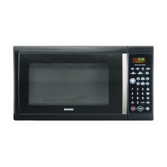
7. OPERATING PROCEDURES A. OVEN CONTROL PANEL 1. DISPLAY. The display includes a clock and indicators that tell you time of day, cooking time settings, and cooking functions selected. 2. QUICK TOUCH SENSOR. This pad allows you to cook most of your favorite foods without having to select cooking times and power levels. - Page 11 B. EASY USE TABLE (6) TIMED COOKING 1. Touch STOP/CLEAR. 2. Touch COOK TIME. (1) KITCHEN TIMER 3. Touch number for cooking time. 1. Touch STOP/CLEAR. 4. Touch POWER. 2. Touch KITCHEN TIMER. 5. Touch number for cooking power level. 3.
-
Page 12: Procedure For Measuring Microwave Energy Leakage
8. PROCEDURE FOR MEASURING MICROWAVE ENERGY LEAKAGE B. MEASURING MICROWAVE ENERGY LEAKAGE A. CAUTIONS (1) Pour 275 15cc of 20 5°C water in a beaker which is (1) Be sure to check a microwave emission prior to servicing ± ± graduated to 600 cc, and place the beaker in the center the oven if the oven is operative prior to servicing. - Page 13 D. MEASUREMENT WITH A FULLY ASSEMBLED OVEN G. POWER OUTPUT MEASUREMENT (1) Fill the test beaker with 59 ˚F(15 ˚C) ~ 75 ˚F(24 ˚C) 1 liter tap (1) After all components, including the outer panels, are water. fully assembled, measure for microwave energy (2) Stir the water in the beaker with thermometer ( ˚F or ˚C) and leakage around the door viewing window, the exhaust measure temperature as T1.
-
Page 14: Disassembly Instructions
9. DISASSEMBLY INSTRUCTIONS (6) Pull down and remove the circuit board from the control IMPORTANT NOTES: panel. (7) Remove the F.P.C connector from the terminal socket. UNIT MUST BE DISCONNECTED FROM ELECTRICAL OUTLET WHEN MAKING REPAIRS, RE-PLACEMENTS, ADJUSTMENTS AND CONTINUITY CHECKS. WAIT AT Remove screw LEAST ONE MINUTE, UNTIL THE HIGH VOLTAGE CAPACITOR IN THE HIGH VOLTAGE POWER... - Page 15 C. DOOR ASSEMBLY / REMOVAL Remove choke cover (1) Open the door. (2) Remove the choke cover very carefully with a flat-blade screwdriver. CAUTION : Be careful not to damage door seal plate by screwdriver. (3) Lift up and push the door. NOTE: 1.
- Page 16 D. MAGNETRON REMOVAL E. REMOVING THE TURNTABLE MOTOR 1) Remove the turntable and rotating ring. (1) Disconnect the wire lead from the magnetron. 2) Lay the unit down on its back. (2) Carefully remove the mounting screws holding the 3) Remove the turntable motor cover. magnetron and the waveguide.
- Page 17 F. HIGH VOLTAGE TRANSFORMER REMOVAL I. REMOVING SENSOR 1) Discharge the high voltage capacitor. 1) Disconnect the leadwire from PCB Assembly. 2) Disconnect the leadwire from magnetron, high voltage 2) Remove a screw securing the sensor duct. transformer, and capacitor. 3) Remove the screw holding the high voltage transformer to the baseplate.
- Page 18 J. INTERLOCK SYSTEM 1) INTERLOCK MECHANISM The door lock mechanism is a device which has been specially designed to eliminate microwave activity when the door is opened during cooking and thus to prevent the danger resulting from the microwave leakage. 2) MOUNTING OF THE PRIMARY/MONITOR/ SECONDARY SWITCHES TO THE LATCH BOARD 3) INSTALLATION AND ADJUSTMENT OF THE LATCH...
-
Page 19: Interlock Continuity Test
10. INTERLOCK CONTINUITY TEST WARNING : FOR CONTINUED PROTECTION AGAINST EXCESSIVE RADIATION EMISSION, REPLACE ONLY WITH IDENTICAL REPLACEMENT PARTS. TYPE NO. SZM-V 16-FA-63 OR VP-533A-OF OR V-5230Q FOR PRIMARY SWITCH TYPE NO. SZM-V 16-FA-62, VP-532A-OF OR V-5220Q FOR MONITOR SWITCH TYPE NO. -
Page 20: Test And Checkout Procedures, And Troubleshooting
11. TEST AND CHECKOUT PROCEDURES, AND TROUBLESHOOTING CAUTIONS 1. DISCONNECT THE POWER SUPPLY CORD FROM THE OUTLET WHENEVER REMOVING THE OUTER CASE FROM THE UNIT. PROCEED WITH THE TEST ONLY AFTER DISCHARGING THE HIGH VOLTAGE CAPACITOR AND REMOVING THE WIRE LEADS FROM THE PRIMARY WINDING OF THE HIGH VOLTAGE TRANSFORMER. - Page 21 COMPONENTS TEST PROCEDURE RESULTS Antenna Gasket Chassis Filament NOTE: When testing the magnetron, be sure to install the magnetron gasket in the correct position and be sure that the gasket is in good condition. HIGH VOLTAGE Measure the resistance. Normal: Momentarily indicates CAPACITOR (Ohm-meter scale: Rx1000) several ohms, and...
-
Page 22: Test Procedure
COMPONENTS TEST PROCEDURE RESULTS RELAY 2 Check for continuity of relay 2 with an ohm- POWER meter. LEVEL (Remove wire leads from relay 2 and operate the unit.) 4 sec 18 sec 6 sec 16 sec 8 sec 14 sec 10 sec 12 sec 12 sec... -
Page 23: Checkout Procedures
B. CHECKOUT PROCEDURES (1) CHECKOUT PROCEDURES FOR FUSE BLOWING CAUTION: REPLACE BLOWN FUSE WITH 20 AMPERE FUSE. PROBLEMS CAUSES Fuse blows immediately after Improper operation of the primary interlock, the door is closed. secondary interlock switches and/or the interlock monitor switch. Fuse blows immediately after the door is opened. - Page 24 (2) CHECKOUT PROCEDURES FOR RELAY - PROBLEM (A) - FAN motor and oven lamp turn on without touching START key when the door is closed. Remove the mate connector of I/O GOOD CON from the circuit board does the unit still operate? Replace the circuit board - PROBLEM (B) -...
- Page 25 (3) CHECKOUT PROCEDURES FOR CIRCUIT BOARD The following symptoms indicate a defective circuit board. (1) The start function fails to operate but the high (4) Some segments of one or more digits do not light up, or voltage Systems, the interlock switches, the door they continue to light up, or segments light when they sensing and the relay check good.
-
Page 26: Troubleshooting
C. TROUBLE SHOOTING WHEN YOU GET A COMPLAINT FROM YOUR CUSTOMER, EVALUATE THE COMPLAINT CAREFULLY. IF THE FOLLOWING SYMPTOMS APPLY, PLEASE INSTRUCT THE CUSTOMER IN THE PROPER USE OF THE MICROWAVE OVEN. THIS CAN ELIMINATE AN UNNECESSARY SERVICE CALL. CAUTIONS 1. - Page 27 (TROUBLE 1) The following visual conditions indicate a probable defective control circuit. 1. Incomplete segments. • Segment missing. • Partial segment missing. • Digit flickering (NOTE: Slight flickering is normal.) 2. Colon does not turn on or blink. 3. A distinct change in the brightness of one or more numbers in display. 4.
- Page 28 (TROUBLE 2) Oven does not operate at all, Display window does not display any figures, and no input is accepted. CONDITION CHECK RESULT CAUSE REMEDY Malfunction of the Replace fuse, Check continuity 1. Fuse blows. Continuity. monitor switch. primary, monitor of monitor switches, and switch (with...
- Page 29 (TROUBLE 3) Display shows all figures set, but oven does not start cooking while desired program times are set and START pad is touched. CONDITION CHECK RESULT CAUSE REMEDY Defective Replace Check continuity 1. Setting time No continuity. secondary switch. secondary switch.
- Page 30 (TROUBLE 5) No microwave oscillation even though oven lamp and fan motor run. (Display operates properly) CONDITION CHECK RESULT CAUSE REMEDY No microwave Defective PCB Replace PCB Disconnect the No continuity. oscillation. assembly. assembly. wire leads from relay 2 and check continuity Continuity.
-
Page 31: Exploded View
#EV# EXPLODED VIEW INTRODUCTION SENSOR OUTER CASE INTERIOR DOOR BASE PLATE LATCH BOARD CONTROL PANEL -30-... -
Page 32: Door Parts
#EV# DOOR PARTS 1013 1005 1004 1002 1000 1003 1001 1006 1007 -31-... -
Page 33: Controller Parts
#EV# CONTROLLER PARTS 2004 2381 2002 2006 W106 2000 -32-... -
Page 34: Oven Cavity Parts
#EV# OVEN CAVITY PARTS W103 3001 3003 3034 W107 3002 3009 3008 W105 -33-... -
Page 35: Latch Board Parts
#EV# LATCH BOARD PARTS W102 4001 4002 4000 4003 4002 4004 -34-... -
Page 36: Interior Parts
#EV# INTERIOR PARTS W101 5014 5010 5001 5016 5041 3006 5012 W109 5003 W208 5007 W110 W109 W101 5000 3007 W101 5002 5015 5009 W208 W109 9000 W101 5006 5018 -35-... -
Page 37: Base Plate Parts
#EV# BASE PLATE PARTS 5008 6000 6001 6007 W101 W108 -36-... - Page 38 #EV# SENSOR PARTS W136 W108 5011 5004 -37-...
- Page 39 P/NO: MFL30502909 Printed in Korea...
Need help?
Do you have a question about the 721.66339 and is the answer not in the manual?
Questions and answers