Table of Contents
Advertisement
Available languages
Available languages
Advertisement
Table of Contents

Subscribe to Our Youtube Channel
Related Manuals for AFG 3.1AT


Summary of Contents for AFG 3.1AT
- Page 1 3.1AT 5.1AT Read the TREADMILL GUIDE before using this OWNER'S MANUAL. Lire le GUIDE DU TAPIS ROULANT avant de se servir du present MANUEL DU PROPRII_TAIRE. Lea la GUJA DE LA CAMINADORA antes de usar este MANUAL DEL PROPIETARIO.
- Page 2 ENGLISH FRANQAIS ESPANOL...
- Page 4 DANGER TO REDUCE THE RISK OF ELECTRICAL SHOCK: Always unplug the treadmill from the electrical outlet immediately after using, before cleaning, performing maintenance and putting on or taking off parts. WARNING TO REDUCE THE RISK OF BURNS, FIRE, ELECTRICAL SHOCK OR INJURY TO PERSONS: •...
- Page 5 WARNING TO REDUCE THE RISK OF BURNS, FIRE, ELECTRICAL SHOCK OR INJURY TO PERSONS: • At NO time should pets or children under the age of 13 be closer to the treadmill than 10 feet. • At NO time should children under the age of 13 use the treadmill.
- Page 6 GROUNDING INSTRUCTIONS This product must be grounded. If a treadmill should malfunction or break down, grounding provides a path of least resistance for electrical current to reduce the risk of electrical shock. This product is equipped with a cord having an equipment-grounding conductor and a grounding plug.
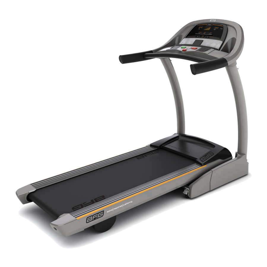
- Page 8 READING RACK/AUDIO CORD CONSOLE CONTROLS DISPLAY WINDOWS SPEAKERS USB PORT AND AUDIO IN JACK CONSOLE WATER BOTTLE HOLDER SAFETY KEY PLACEMENT GRIP PULSE HANDRAILS ON/OFF SWITCH HANDLEBARS CONSOLE MAST CIRCUIT BREAKER POWER CORD MOTOR COVER FOOT LOCK LATCH (UNDERNEATH DECK) MAIN FRAME BOOT (5.1AT shown) CAUTION AVERTISSEMENT...
-
Page 9: Parts Included
PRE ASSEMBLY TOOLS INCLUDED: 8 mm T-Wrench 5 mm T-Wrench UNPACKING 5 mm L-Wrench Place the treadmill carton on a level flat surface. It is recommended that you place a Screwdriver protective covering on your floor. Take CAUTION when handling and transporting this unit. - Page 10 2 mm8 Qty:20SCREW(L)mm2 Qty: 6 Qty: 6 Qty: 6 * This step is for 5.1AT models only. For 3.1AT models, proceed to page 12. SCREWS Cut the yellow banding straps and lift the running deck upward to remove all contents...
- Page 11 5.1AT ASSEMBLY STEP 1 CONTINUED Pull LEAD WIRE through RIGHT CONSOLE MAST. After pulling the LEAD WIRE through the mast, the top of the CONSOLE CABLE should be located at RIGHT CONSOLE MAST the top of the mast. Detach and discard LEAD WIRE. NOTE: DO n0t pinch console cable when placing the mast onto the main frame bracket.
- Page 12 3°1AT ASSEMBLY STEP 1 * This step is for 3.1AT models only. HARDWARE FOR STEP 1 : Cut the yellow banding straps and lift the running SPRING WASHER ARC WASHER (C) deck upward to remove all contents from underneath 20 mm 8.2 mm...
-
Page 13: Assembly Step
ASSEMBLY STEP 2 Open HARDWARE FOR STEP 2. HARDWARE FOR STEP 2 : With the CONSOLE upside down, attach the BOLT (E) SPRING WASHER FLAT WASHER (F) CONSOLE MAST CAPS to the CONSOLE 20 mm 8,2 mm 8,2 mm Qty: Qty: Qty: using 6 BOLTS (E), 6 SPRING... - Page 14 ASSEMBLY STEP 3 HARDWARE Open HARDWARE FOR STEP 3. FOR STEP 3 : Connect the CONSOLE CABLES, carefully BOLT (G) ARC WASHER SPRING WASHER tucking wires in masts to avoid damage. It may 20 rnrn 8.2 mm 8,2 rnrn Qty: 6 Qty: 6 Qty: 6 be helpful to have a second person for this step.
- Page 15 3°1AT ASSEMBLY STEP 4 * This step is for 3.1 AT models only. HARDWARE FOR STEP 4 : Open HARDWARE FOR STEP 4. SCREW Slide MAIN FRAME BOOT clown over MAIN FRAME 20 mm Qty: 4 BRACKET. Attach MAIN FRAME BOOTS using 4 SCREWS (L). MAIN FRAME BOOT SCREWS (L)
- Page 16 ASSEMBLY STEP 5 Open HARDWARE FOR STEP 5. HARDWARE FOR STEP 5 : Connect the CONSOLE CABLES, discard the twist tie and slide the CONSOLE CABLES into the SPRING WASHER ARC WASHER BOLT (H) 12 mm 6.2 mm 6.2 mm CENTER BAR.
- Page 17 ASSEMBLY STEP 8 Open HARDWARE FOR STEP 6. HARDWARE FOR STEP 6 : Attach CONSOLE CABLES from HANDLEBARS BOLT (K) SPRING WASHER (B) FLAT WASHER (F) to CONSOLE CABLES from CONSOLE. Gently 15 mm 8.2 mm 8.2 mm tuck excess cable into CONSOLE before sliding the Qty: 6 Qty: 6 Qty:...
-
Page 21: Operation
CONSOLE OPERATION Note: There is a thin protective sheet of clear plastic on the overlay of the console that should be QUICK ADJUST KEYPAD removed before use. LED DISPLAY WINDOWS: time, incline, distance, speed, date and clock. ALPHANUMERIC DISPLAY WINDOW: calories, heart rate, pace (5.1ATonly) PROFILE"... -
Page 22: Program Profiles
18:W l:1 ..': 2./33 I8:LID 2.8 3 ..:: OOOO00 OO0000 • time oooooooo • distance • time oooooooo • distance OO0000000O OOOOOOOOOO speed speed _ncHne oooooooooooo _ncHne oooooooooooo OOOOOOOOOOOOOO O00000000OOOO0 15 1 calories heart rate 9.0 3 • clock date DISPLAY Wl NDOWS •... -
Page 23: Getting Started
GETTI NG STARTED DATE AND CLOCK SETUP Check to make sure no objects are placed on the belt that 1) Enter Setup mode: Press and hold the 1 will hinder the movement of the treadmill. and 2 buttons for 3 seconds. Plug in the power cord and turn the treadmill UseAv on the PROGRAMMING... -
Page 24: Program Information
PROGRAM INFORMATION NOTE: If speed or incline changed during your workout, remaining segments will be affected accordingly. 1) MANUAL: Adjust your speed and incline manually during your workout. Cool Down Segments Warm-Up SPEED INTERVALS: Walk or run a series of Time 4:00 M_N 90SEC... - Page 25 4) STAMINA BUILDER: Promotes weight loss by increasing and decreasing the incline, while keeping you in your fat burning zone. Segments are repeated until selected time is reached. Segment Warm coo] Down Level1 Seconds 4:00M,N 35:00 nc ne 3.0 I Segment Warm coo]...
- Page 26 PROGRAM INFORMATION 112131415161718 Cool Down Warm Up Se,qment 4 :OOM_N 4:00 M_N Time Eachseqmentis30seconds Incline WEIGHT LOSS: Promotes weight Level 1 .O Speed loss by increasing and decreasing Incline Level 2 the speed and incline, while keeping Speed 1 .O Incline you in your fat burning zone.
- Page 27 FOOT HILLS: Simulates a hill 11213141516171819110111112113114115 Cool Down Segment Warm 4:00 u_N Time 4:00 Each segment is 30 seconds ascent and descent. This program 1.0 3.0 1.0 3.0 2.0 3.0 2.0 4.0 2.0 3.0 2.0 3.0 1.0 1.0 1.0 1.0 0.0 1.0 0.0 Level helps tone muscle and improve 1.0 3.0 2.0 3.0 2.0 3.0 3.0 4.0 3.0 3.0 2.0 3.0 2.0 3.0 1.0...
-
Page 28: Heart Rate Trai Ni Ng
PROGRAM INFORMATION HEART RATE TRAI NI NG VERY HARD 171 - 190 BPM The first step in knowing the right intensity for your Fit persons and for athletic training 90 - 100% training is to find out your maximum heart rate (max HARD 2- 10 MJN 152-171... - Page 29 HR INTERVALS (5,1AT ONLY): Automatically adjusts peak and valley incline levels within your desired heart rate. Perfect for providing an intense workout with recovery bursts. Time-based goal. 1) Set WORK interval time using ,6, v on the PROGRAMMING BUTTON or the KEYPAD and press ENTER.
- Page 30 Because your new treadmill is equipped with AFG's exclusive PROFILE Performance Tracker, you've taken an important step towards achieving your fitness goals.
- Page 31 WEEKLY TOTAL: View your accumulated data from the last Sunday to the present day. NOTE: This data is based on week to date NOT the previous seven days. For instance, if you have not used the machine since Sunday, console will read zeros.
- Page 32 USING YOUR CD / MP3 PLAYER 1) Connect the included AUDIO ADAPTOR CABLE to the AUDIO IN JACK on the top right of the console and the headphone jack on your CD / M P3 player. Use your CD / MP3 player buttons to adjust song settings.
-
Page 34: Exclusions And Limitations
EXCLUSIONS AND LIMITATIONS WEIGHT CAPACITY Who IS covered: 3.1AT = 325 Ibs (147 kilograms) • The original owner and is not transferable. 5.1AT = 350 Ibs (159 kilograms) What IS covered: FRAME = LIFETIME • Repair or replacement of a defective... - Page 35 SERVICE/RETURNS ormaintenance oftheequipment. The manufacturer does In-home service is available within 150 miles of the nearest notprovide monetary orother compensation forany such authorized Service Provider (Mileage beyond 150 miles repairs orreplacement parts costs, including butnotlimited from an authorized service center is the responsibility togym membership fees, work time lost, d iagnostic visits,...
- Page 36 AN3x2 _852x8 _P22 C_x2 ZC4x6 H37x2 Z02x6 Z03x6 P23. M14! B7_2 880x2 K18_ _ K28x2 B53x2...
- Page 37 REF # DESCRIPTION Nut;NLK;M8X1.25P;;BZN;; Drive Motor Set;SEMI-ASSY;DOWN;TM426-1 Washer;FLT; 8.3X 16.0X1.3T;;BZN; Side Rail Set;SA;L;TM426-1 US;-;-; Screw;HH;3/8-16UNCX50L-14L;;HE;G8.8;;;P- Side Rail Set;SA;R;TM426-1 US;-;-; Nut;NLK;3/8'-I 6UNC;;BAN;; HR Grip Set;F;TM427-1 US;HB; Washer;ELT; 10.5X 20.0X2.0T;;BZN; Handlebar Set;E;TM427-1 US;HB; Screw;HH;3/8-16UNCX60L-18L ;;H E;;;;P-T Console Set;SA;-;TM426-1 US;-;-; Screw;B H;M4X0.7PX 10L;;PH;;BAN;; Elevation Rack Set;;;;;PAINTING;DM328;;;...
- Page 38 ZOSX6 Z()2X6 /P24 B79X2 r_;6x2...
- Page 39 REF # DESCRIPTION Screw;HH;3/8-16UNCX50L-14L;;HE;G8.8;;;P- Motor Set;U;TM427-1 US;MT; Nut;NLK;3/8'-I 6UNC;;BAN;; Console Set;U;TM427-1 US;CS; Washer;ELT; 10.5X 20.0X2.0T;;BZN; Arm Rest Set;F;TM427-1 US;HB; Screw;HH;3/8-16UNCX60L-18L ;;H E;;;;P-T HR Grip Set;F;TM427-1 US;HB; Screw;BH;M4X0.7PX 10L;;PH;;BAN;; Side Rail SetL;R;TM427 Nut;HX;M6X1.0P;SS41 ;BZN;; Side Rail Set;L;TM427 Bolt; BH; M4X12 Elevation Rack Set;;;;;PAINTING;DM328;;; Washer;SPL;...
- Page 42 DANGER POUR RI:!:DUIRE LE RISQUE DE DI=CHARGE I:!:LECTRIQUE : Toujours debrancher le tapis roulant de la prise de courant immediatement apres I'avoir utilise, avant de le nettoyer et de proceder I'entretien, et avant d'y poser des pieces ou de les en deposer. AVERTISSEMENT POUR RF:DUIRE LE RISQUE...
- Page 43 AVERTISSEMENT POUR RF:DUIRE LE RISQUE DE BROLURES, D'INCENDIE, DE DF:CHARGE F:LECTRIQUE OU DE BLESSURE • Tenir les enfants de moins de 13 ans de m_me que les animaux familiers D.au moins 3 m (1 0 pi) du tapis roulant EN TOUT TEMPS. •...
-
Page 44: De Mise .& La Terre
INSTRUCTIONS DE MISE .& LA TERRE Cet appareil doit 6tre mis & la terre. En cas de dysfonctionnement ou de defaillance du tapis roulant, la mise & la terre assure un trajet de resistance moindre pour le courant electrique et reduit le risque de decharge electrique. - Page 46 SUPPORT DE LECTURE/RAINURE POUR -- FENETRES D'AFFICHAGE ET TOUCHES CORDON AUDIO DE COMMANDE DE LA CONSOLE HAUT-PARLEURS PORT USB ET PRISE D'ENTRI_E AUDIO CONSOLE PORTE-BIDON EMPLACEMENT DE LA CLE_ DE SE_CURITE_ POIGNE_ES DU CARDIO- FRE_OUENCEMI_TRE INTERRUPTEUR POIGNI_ES MARCHE-ARRET COUPE-CIRCUIT MONTANT DE CONSOLE CORDON COUVERCLE...
- Page 47 PREoASSEMBLAGE OUTILS INCLUS Cle a. manche en T, de 8 mm Cle & manche en T, de 5 mm DEBALLAGE Cle & manche en L, de 5 mm Poser I'emballage du tapis roulant sur une surface plane. II est conseille de placer une Tournevis toile de protection...
- Page 48 5°1AT ETAPE 1 DE L ASSEMBLAGE VISSERIE .& UTILISER LORS DE UC:TAPE 1 : RONDELLE RONDELLE 20 mm 20 mm ELASTIQU E (B) EN ARC 12 mm Quantit(_ 8,2 mm 8,2 mm Quantit(_ Quantit_ BOULON Quantit(_ Quantit_ * Cette etape ne concerne que le modele 5.1AT.
- Page 49 5°1AT ETAPE 1 DE L ASSEMBLAGE (SUITE) Passer le FIL DE GUIDAGE dans le MONTANT DE CONSOLE DROIT. Cela fait, le bout du CABLE DE LA CONSOLE doit se trouver en haut du montant. MONTANT DE CONSOLE DROIT Detacher le FIL DE GUlDAGE et le mettre au rebut.
- Page 50 3°1AT ETAPE 1 DE L ASSEMBLAGE * Cette etape ne concerne que le modele 3.1 AT. VISSERIE A UTILISER LORS DE I.'€:TAPE 1 : Couper les bandes de cerclage jaunes et relever la plate-forme. Retirer toutes les pieces qui se trouvent RONDELLE RONDELLE ELASTIQU E (B)
- Page 51 ETAPE 2 DE L ASSEMBLAGE Ouvrir le SACHET DE VISSERIE A UTILISER VISSERIE A UTILISER LORS DE L'I_TAPE 2 : LORS DE L'I_TAPE2. RONDELLE CONSOLE sens dessus-dessous, fixer les BOULON fFr-.\\ RONDELLE PLATE (F) CHAPEAUX DE MONTANT DE CONSOLE a.la 8,2 mm 20 mm I_LASTIQUE...
- Page 52 ETAPE 3 DE L ASSEMBLAGE Ouvrir le SACHET DE VISSERIE .& UTILISER VISSERIE .& UTILISER LORS DE L'C:TAPE 3 : LORS DE I.'I_TAPE 3. RONDELLE Connecter les CABLES DE LA CONSOLE, en les BOULON RONDELLE 20 mm I_LASTIQU E (B) EN ARC (C) tirant delicatement clans les montants...
- Page 53 3olAT _ ETAPE 4 DE L_ASSEMBLAGE * Cette etape ne concerne que le modele 3.1AT. VISSERIE A UTILISER LORS DE I.'€:TAPE 4 i Ouvrir le SACHET DE VlSSERIE A UTILISER LORS DE L'I_TAPE 4. VlS (L) 20 mm Faire glisser la GAINE DU BATI vers le bas sur le Quantit_ SUPPORT DU BATI.
- Page 54 ETAPE 5 DE UASSEMBLAGE Ouvrir le SACHET DE VISSERIE A UTILISER VISSERIE A UTILISER LORS DE I.,I_TAPE 5 : LORS DE L'I_TAPE 5. Connecter LES CABLES DE LA CONSOLE, jetez RONDELLE RONDELLE BOULON 12 mm I_LASTIQU E (I) EN ARC (J) I'attache et faites glisser LES CABLES DE LA Quantit_ 6_2 mm...
- Page 55 ETAPE G DE L ASSEMBLAGE Ouvrir le SACHET DE VISSERIE A UTILISER VISSERIE _. UTILISER LORS DE UETAPE 6 : LORS DE I.'I_TAPE 6. Brancher les CABLES qui relient la CONSOLE RONDELLE BOULON RONDELLE PLATE (F) aux POIGNI_ES. Introduire I'exces de c&ble avec 8_2 mm Quantit_...
- Page 59 FONCTIONNEMENT DE LA CONSOLE Remarque : Avant d'utiliser la console, il faut enlever la fine pellicule protectrice en plastique CLAVIERDE REGLAGE RAPIDE(K) la recouvre. FENI_TRES D'AFFICHAGE .& DEL : Affichent TOUCHES DE REGLAGE DE LA duree, I'inclinaison, la distance, la vitesse, la date VITESSE : Servent A regler la vitesse par petits et I'heure.
- Page 60 15: D ..': 2./33 I5:LID 2.8 3 ..:: COCO00 CO0000 • time oooooooo • distance • time oooooooo • distance OO0000000O OOOOOOOOOO speed speed incline oooooooooooo incline oooooooooooo OOOOOOOOOOOOOO O00000000OOOO0 15 1 calories heart rate 9.0 9 • clock date FENF:TRES D'AFFICHAGE CALORIES...
-
Page 61: Pour Commencer
REGLAGE DE LA DATE POUR COMMENCER ET DE L'HORLOGE 1) S'assurer que rien n'est sur le tapis roulant ou ne risque d'en entraver le mouvement. 1) Passage en mode de reglage : Appuyer sur les touches et 1 et 2 et les tenir pendant 2) Brancher le cordon d'alimentation... - Page 62 INFORMATIONS RELATIVES AUX PROGRAMMES NOTA : Si la vitesse ou I'inclinaison est modifiee au cours de la seance d'entrafnement, les autres segments seront modifies consequence. 1) MANUAL (MANUEL) : Reglage manuel de la vitesse et de I'inclinaison au cours de la seance Segments Echauffement Recup6ration...
- Page 63 4) STAMINA BUILDER (ACCROISSEMENT DE L'ENDURANCE) : Favorise la perte de poids en elevant et en reduisant I'inclinaison, tout en maintenant dans la zone oQ I'on brQle les graisses. Les segments se repetent jusqu'& ce que la duree choisie soit ecoul6e. Segment Echauffement Recuperation...
- Page 64 I N FORMATIONS RELATIVES 112131415161718 Echauffement Recuperation Se,qment AUX PROGRAMMES 4:00 M_.. 4 :OOM_N. Duree Chaquesegmentdure30secondes Inclinsison Niveau Vitesse 5) WEIGHT LOSS (PERTE DE POIDS) Inclinsison Niveau Favorise la perte de poids en elevant et Vitesse Inclinsison en reduisant la vitesse et I'inclinaison, Niveau Vitesse tout en maintenant...
- Page 65 11213141516171819110111112113114115 7) FOOT HILLS (CONTREFORTS) Seqment [_chauffement Recuperati0n 4:00 MIN. Duree 4:00 M_N. Chaque segment dure 30 secondes. Simule I'ascension d'une colline 1,0 3,0 1,0 3,0 2,0 3,0 2,0 4,0 2,0 3,0 2,0 3,0 1,0 1,0 1,0 1,0 0,0 1,0 0,0 Niveau et la descente.
- Page 66 INFORMATIONS RELATIVES AUX PROGRAMMES ENTRAJNEMENT BASF: SUR LA FRF:QUENCE CARDIAQUE La premiere etape pour trouver I'intensite appropriee de votre entrainement consiste & decouvrir votre frequence cardiaque maximale (FC maximale = 220 - votre TRES DURE Personnes en forme et entrainement 171 a 190 B/MIN 90%_100%...
- Page 67 HR INTERVALS (INTERVALLES DE TRAVAIL ET DE REPOS) (5.1AT UNIQUEMENT) : Ajuste automatiquement les niveaux d'inclinaison maximale et minimale au cours des intervalles de travail et de repos clans votre zone de frequence cardiaque cible. Parfait pour procurer un exercice intensif entrecoupe d'intervalles de repos. Objectif de duree. 1) Regler la duree des intervalles de TRAVAIL &...
- Page 68 I 'acquisition de ce nouveau tapis roulant 6quipe du systeme de suivi du conditionnement physique PROFILE exclusif & AFG est une etape importante vers la concretisation de vos objectifs d'entraTnement.
- Page 69 WEEKLY TOTAL (TOTAL HEBDOMADAIRE) : Visualisation des donnees cumulees depuis le dimanche prec6dent. REMARQUE : Ces donnees concement la semaine en cours et NON les sept jours prec6dents. Par exemple, si on n'a pas utilise la machine depuis le dimanche prec6dent, la console affiche des zeros.
- Page 70 UTILISATION D'UN LECTEUR DE CD/BALADEUR Connecter le CABLE D'ADAPTATEU R AUDIO fourni a. la PRISE D'ENTRI_E AUDIO a. la partie superieure du c6te gauche de la console a. la prise pour casque d'ecoute du lecteur de CD/baladeur MP3. Utiliser les boutons du lecteur de CD/baladeur MP3 pour regler les caracteristiques...
-
Page 72: Exclusions Et Limitations
COMPOSANTS €:LECTRONIQUES ET PIC:CES le gel ou d'autres catastrophes naturelles quelle qu'en 3.1AT = 3 ANS / 5.1AT = 5 ANS soit la nature, une reduction, fluctuation ou defaillance d'alimentation de quelque origine que ce soit, des... - Page 73 des privations dejouissance oud'utilisation, oud'autres Si la garantie du fabricant est expiree mais si I'appareil dommages immateriels dequelque nature que cesoit ben6ficie d'une prolongation de garantie, consulter enrelation avec I'achat, I'utilisation, lareparation contrat de prolongation de garantie pour les ressources I'entretien deI'equipement.
- Page 74 AN3x2 _852x8 _P22 C_x2 ZC4x6 H37x2 Z02x6 Z03x6 P23. M14! B7_2 880x2 K18_ _ K28x2 B53x2...
- Page 75 N°DEREF, Dr_$1GNATION Ecrou Ensemble de moteur d'entrainement Rondelle plate Ensemble de rail lat@al; gauche Vis b. t6te hexagonale Ecrou Ensemble de rail lateral; droit Ensemble de poignees du cardio-frequencemetre; avant Rondelle plate Ensemble de poignees d'exercice; avant Vis b. t6te hexagonale Ensemble de console...
- Page 76 ZOSX6 Z()2X6 /P24 B79X2 r_;6x2...
- Page 77 N°DEREF, Dr_SIGNATION Vis #. t6te hexagonale Ecrou Ensemble de moteur; superieur Ensemble de console Rondelle plate Ensemble d'accoudoir; avant Vis & t6te hexagonale Vis & t6te ronde Ensemble de poignees du cardio-fr6quencemetre; avant Ensemble de rail lateral droit Ecrou hexagonal Boulon &...
- Page 80 PELIGRO A FIN DE ELIMINAR EL RIESGO DE DESCARGAS ELF:CTRICAS: Siempre desconecte la caminadora del tomacorriente inmediatamente despues de usarla, antes de limpiarla, de darle mantenimiento, y de instalar o quitar piezas. ADVERTENCIA A FIN DE ELIMINAR EL RIESGO DE QUEMADURAS, INCENDIOS, DESCARGAS ELF:CTRICAS...
- Page 81 ADVERTENCIA A FIN DE ELIMINAR EL RIESGO DE QUEMADURAS, INCENDIOS, DESCARGAS ELF:CTRICAS O LESIONES A PERSONAS: • En NINGON momento deben acercarse a menos de 3 metros (1 0 pies) de la caminadora nifios menores 13 afios de edad o mascotas. •...
- Page 82 INSTRUCCIONES DE CONEXION A TIERRA Es necesario conectar a tierra este aparato. Si su caminadora Ilegara a tener alguna falla o si se Ilegara a descomponer, la conexi6n a tierra proporciona una ruta de menor resistencia a la corriente electrica para reducir el riesgo de que se produzca una descarga...
- Page 84 CONTROLES DE LA CONSOLA ESTANTE DE LECTURA/RANURA PARA Y VENTANILLAS DE INDICADORES EL CABLE DE AUDIO BOCINAS PUERTO USB Y ENCHUFE ENTRADA DE AUDIO PORTABOTELLAS CONSOLA LUGARPARALALLAVE EMPUNADURAS DESEGURIDAD SENSOR DEPULSO INTERRUPTOR BARRASDESUJEClON ENCENDIDO Y APAGADO POSTE DE LA CONSOLA CORTAClRCUITO CABLE DE CORRIENTE...
-
Page 85: Piezas Incluidas
PREENSAMBLAJE HERRAMIENTAS INCLUIDAS: Llave en T de 8 mm Llave en T de 5 mm DESEMPAQUE Llave en L de 5 mm Destornillador Coloque la caja en que viene la caminadora sobre una superficie plana y nivelada. recomendamos colocar una cubierta protectora sobre el piso bajo la maquina. - Page 86 Cantidad: Cantidad: ORNILLO Cantidad: Cantidad: * Este paso es solo para el modelo 5.1 AT. Para modelos 3.1AT, pase a la pa.gina 88. TORNILLOS Corte el enfajillado amarillo, levante la plataforma hacia arriba, y retire todo Io que haya debajo de la plataforma.
- Page 87 5olAT PASO 1 DE ENSAMBLAJE (CONTINUACION) Meta el ALAMBRE DE ALIMENTACION DEL CABLE por el POSTE DERECHO DE LA CONSOLA. Una vez que hayapasado todo el alambre de alimentacion POSTE DERECHO DE LA CONSOLA del cable a traves del poste, la punta superior del CABLE DE LA CONSOLA debe quedar en la parte superior del poste.
- Page 88 3olAT PASO 1 DE ENSAMBLAJE * Este paso es solo para el modelo 3.1AT. TORNILLERJA PARA EL PASO 1:1 Corte el enfajillado amarillo, levante la plataforma hacia arriba, y retire todo Io que haya debajo de la ARANDELA ARANDELA 20 mm...
- Page 89 PASO 2 DE ENSAMBLAJE Abra la BOLSA DE TORNILLERiA PARA EL PASO 2. TORNILLERJA PARA EL PASO Con la CONSOLA de cabeza, fije las TAPAS DE LOS POSTES DE LA CONSOLA a la CONSOLA ARANDELA TORNILLO f_\\ ARANDELA PLANA (F) con 6 TORNILLOS (E), 6 ARANDELAS Cantidad: 6 8.2 mm...
- Page 90 PASO 3 DE ENSAMBLAJE Abra la BOLSA DE TORNILLERIA PARA EL PASO 3. PARA EL PASO 3: TORNILLERJA Conecte los CABLES DE LA CONSOLA, metiendo ARANDELA ARANDELA con cuidado los cables dentro de los postes para TORNILLO E LASTICA (B) DE ARCO (C) 20 mm evitar que sufran dahos.
- Page 91 3olAT _ PASO 4 DE ENSAMBLAJE * Este paso es s61opara el modelo 3.1 AT. TORNILLERJA PARA EL PASO 4: Abra la BOLSA DE TORNILLERfA PARA EL PASO 4. TORNILLO Meta el GUARDAPOLVO DEL BASTIDOR 20 mm Cantidad: PRINCIPAL hacia abajo sobre la MI_NSULA DEL BASTIDOR PRINCIPAL.
- Page 92 PASO 5 DE ENSAMBLAJE Abra la BOLSA DE TORNILLERIA PARA EL PASO 5. TORNILLERJA PARA EL PASO 5: Conecte LOS CABLES DE LA CONSOLA, deseche ARANDELA TORNILLO (FF_\\ ARANDELA el lazo de torcedura y deslice LOS CABLES DE LA DE ARCO CONSOLA en LA BARRA CENTRAL.
- Page 93 PASO 6 DE ENSAMBLAJE Abra la BOLSA DE TORNILLERIA PARA EL PASO 6. TORNILLER|A PARA EL PASO 6: Conecte los CABLES DE LA CONSOLA provenientes de las BARRAS DE SUJECION ARANDELA TORNILLO (FF_\ ARANDELA PLANA (F) con los CABLES DE LA CONSOLA que vienen 15 mm Cantidad: 6...
- Page 97 FUNCIONAMIENTO DE LA CONSOLA Nota: La consola tiene una cubierta pla.stica delgada de proteccion que es necesario quitar antes de usar TECLADO DECAMBIORAPIDO (K) la consola. PANTALLAS CON DIODOS LUMINOSOS: TECLADO DE CAMBIO RAPIDO: Se usa Indican el tiempo, la inclinacion, la distancia, para Ilegar m,_s rapidamente a la velocidad...
- Page 98 15:ff 0 ..': B.03 I6:ff D 2.8 3 ..:: OOOO00 OO0000 • time oooooooo • distance • time oooooooo • distance OO0000000O OOOOOOOOOO speed speed incline oooooooooooo incline oooooooooooo OOOOOOOOOOOOOO O00000000OOOO0 15 1 calories heart rate 9.0 9 • clock date VENTANILLAS DE INDICADORES...
-
Page 99: Para Empezar
PARA EMPEZAR PARA PONER LA FECHA Y LA HORA 1) Verifique que no haya objetos en la banda que pudieran impedir el funcionamiento de la caminadora. 1) Para ingresar al modo de configuracion: 2) Conecte el cable de corriente y encienda la caminadora. - Page 100 INFORMACION DE LOS PROGRAMAS NOTA : Si usted modifica la velocidad o la inclinacion durante su sesion de ejercicio, los segmentos restantes se vera.n afectados segun corresponda. 1) MANUAL: Le permite ajustar la velocidad la inclinacion manualmente durante su sesion Segmentos Calentamiento Enfriamiento...
- Page 101 4) STAMINA BUILDER (DESARROLLO DE RESISTENCIA): Promueve el control de peso al aumentar y reducir la inclinacion, al tiempo que le mantiene dentro de su zona 6ptima para quemar grasa. Los segmentos se repiten hasta que se Ilega al tiempo seleccionado.
- Page 102 INFORMACION 112131415161718 Calentamiento Enfriamiento Seqmento 4:00 M_N LOS PROGRAMAS 4:00 M_N. Cadaseqmentodura3Osequndos Tiempo Inclinacion Nivel 1 1 .O Velocidad WEIGHT LOSS (CONTROL Inclinacion Nivel Velocidad PESO): Promueve el control de peso 1 .O Inclinacion al aumentar y reducir la velocidad y la Nivel Velocidad...
- Page 103 1 I 2 I 3 I 4 I 5 I 6 I 7 I 8 I 9 110111112113114115 Enfriamiento FOOT HILLS (COLINAS Seqmento Calentamiento Tiempo 4:00 M_N. Cada se,qmento dura 30 sequndos 4:00 M_N. LEVES): Simula subir y bajar Nivel 1 0.0 1.0 0.0 1.0 1.0 3.0 1.0 3.0 2.0 3.0 2.0 4.0 2.0 3.0 2.0 3.0 1.0 1.0 1.0 1.0 0.0 1.0 0.0 colinas...
- Page 104 INFORMACI()N DE LOS PROGRAMAS ACONDICIONAMIENTO BASADO EN EL RITMO CARD|ACO El primer paso para determinar la intensidad adecuada para su acondicionamiento es determinar su ritmo cardiaco maximo (220 - su edad). El metodo basado en la edad es una predicci6n estadistica MUY FUERTE 171 - 190 Personas en buena forma fisica...
- Page 105 HR INTERVALS (INTERVALOS DE RITMO CARDIACO) (SOLO EL MODELO 5.1AT): Ajusta en forma automa.tica niveles de inclinaci6n de cimas y valles dentro de su ritmo cardiaco deseado. Perfecto para producir una sesi6n de ejercicio intenso con breves momentos de recuperaci6n. Meta basada en tiempo.
- Page 106 Io hacen. Debido a que su nueva caminadora esta. equipada con el exclusivo seguidor de resultados PROFILE de AFG, usted ha tomado un paso importante en su proposito de alcanzar sus metas de salud fisica. El software PROFILE...
- Page 107 WEEKLY TOTAL (TOTAL SEMANAL): Yea sus datos acumulados desde el Wtimo domingo hasta el dia actual de la semana. NOTA: Estos datos se basan del principio de la semana actual hasta el dia actual, NO en los ultimos siete dias. Por ejemplo, usted no ha usado la ma.quina desde el domingo, la consola indica ceros.
- Page 108 PARA USAR SU REPRODUCTOR DE CD/MP3 1) Conecte el CABLE ADAPTADOR DE AUDIO que se incluye, al ENCHUFE DE ENTRADA DE AUDIO que esta. en el lado derecho superior de la consola y al enchufe para auriculares de su reproductor CD/MP3.
- Page 110 EXCLUSIONES Y LIMITACIONES CAPACIDAD DE PESO A quien protege esta garantia: 3.1AT = 147 kg (325 Ib) • AI propietario original y la garantia no es transferible. 5.1AT = 159 kg (350 Ib) QUI_ protege esta garantia: BASTIDOR = DE POR VIDA •...
- Page 111 ofrece c ompensaci6n monetaria nideotro tipopordichas SERVICIO Y DEVOLUCIONES reparaciones nicostos d ereemplazo depiezas, incluso pero • Hay servicio a domicilio solo a menos de 240 km del sinlimitarse acuotas demembresia engimnasios, tiempo proveedor de servicio autorizado ma.s cercano (a distancias perdido detrabajo o labores, servicio dediagn6stico, servicio mayores de 240 km de un proveedor...
- Page 112 AN3x2 _852x8 _P22 C_x2 ZC4x6 H37x2 Z02x6 Z03x6 P23. M14! B7_2 880x2 K18_ _ K28x2 B53x2...
- Page 113 N,° DE REE DESCRIPCI()N Tuerca Conjunto de motor de transmisi6n Arandela; plana Conjunto de riel lateral; izquierdo Tornillo; cabeza hexagonal Tuerca Conjunto de riel lateral; derecho Conjunto de empuEaduras sensor de pulso; delantero Arandela; plana Conjunto de barras de sujeci6n, delantero Tornillo;...
- Page 114 ZOSX6 Z()2X6 /P24 B79X2 r_;6x2...
- Page 115 N.° DE REE DESCRIPCI()N Tornillo; cabeza hexagonal Tuerca Conjunto de motor; superior Conjunto de consola Arandela; plana Con junto de descansabrazos; delantero Tornillo; cabeza hexagonal Conjunto empuEaduras sensor de pulso; delantero Tornillo; cabeza de bot6n Conjunto de riel lateral; derecho Tuerca;...
- Page 116 Internet. visiter notre site Web. 3.1AT 5.1AT Rev. 1.3 J :¢ 2011 Advanced Fitness Group Designed & Engineered in the U.S.A. ° Made in China I Conr_u et developpe aux Etats-Unis. ° Fabriqu6 en Chine I Disef_o y tecnologia de los EE.UU.
Need help?
Do you have a question about the 3.1AT and is the answer not in the manual?
Questions and answers
Why would my agf 3.1at treadmill motor get so hot you cant touch it? Thank you
The AFG 3.1AT treadmill motor may get excessively hot if the air opening is blocked or not kept clean. The manual states to never operate the treadmill with the air opening blocked and to keep it clean and free of lint, hair, and similar debris. Blocked air openings can restrict airflow, causing the motor to overheat.
This answer is automatically generated
My treadmill won’t start and is putting the code 5103 on the left side of the screen where usually the time is. The code 07 is on the right side of the screen where the distance usually appears. Is it possible to fix my treadmill or it means that it is done?