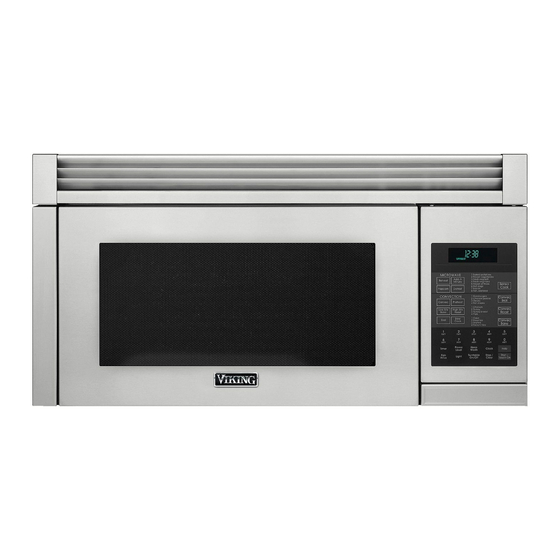
Viking RVMHC330 Installation Manual
Convection microwave hood
Hide thumbs
Also See for RVMHC330:
- Use & care manual (40 pages) ,
- Installation manual (29 pages) ,
- Manual (6 pages)
Table of Contents
Advertisement
Available languages
Available languages
Quick Links
Advertisement
Table of Contents

Related Manuals for Viking RVMHC330


Summary of Contents for Viking RVMHC330
-
Page 1: Installation Guide
Installation Guide Convection Microwave Hood... -
Page 2: Important-Please Read And Follow
IMPORTANT–Please Read and Follow! • Please read all instructions thoroughly before installing the Convection Microwave Hood. Two people are recommended to install this product. • If a new electrical outlet is required, its installation should be completed by a qualified electrician before the Convection Microwave Hood is installed. -
Page 3: Electrical Grounding Instructions
140 feet. electrical instructions, consult a qualified electrician or serviceperson. • Neither Viking Range, LLC nor the dealer can accept any liability for damage to the oven or personal injury resulting from failure to observe the correct electrical connection procedures. -
Page 4: Tools Recommended For Installation
Tapping Screw 4 x 12 mm Parts shown not to common scale. XOTS740P12000 Exhaust Damper Assembly FFTA-B004MRK0 Basic Specifications Microwave oven description VMoR205, cVMoR205, RdMoR206, RVMhc330 Overall Width 29-15/16" (76.0 cm) Overall Height from Bottom 16-11/32" (41.5 cm) Overall Depth from Rear 15-9/32"... -
Page 5: Ventilation System
Ventilation System (Preparing Oven for Installation) This Convection Microwave Hood is designed for adaptation to three types of hood ventilation systems. Hood Fan Unit Select the type required for your installation. REciRculating — non-vented, ductless. Follow installation procedure (A). Recirculating requires the use of the Charcoal Filter, which has been installed in the oven. - Page 6 Ventilation System (Preparing Oven for Installation) (C) Vertical Exhaust: Outside Ventilation Fan Cover Bracket • Remove and save 4 screws and fan cover bracket as shown in figure 5. Withdraw hood fan unit. See figure 6. (A) Rotate 90˚ HORIZONTAL EXHAUST: Replace the fan cover bracket. Make sure the fan blades are visible through the rear openings in the oven before proceeding.
-
Page 7: Oven Installation
Oven Installation THIS OVEN CANNOT BE PROPERLY INSTALLED WITHOUT notE: REFERRING TO THE MOUNTING INSTRUCTIONS Before insertion, be sure you leave a space more than FOUND ON WALL AND TOP CABINET TEMPLATES. the thickness of the wall between the Mounting Plate and the end of each of the Toggle Nuts (in the closed Mounting Plate position). - Page 8 Oven Installation MOUNTING OVEN TO THE WALL: Hang the oven on MOUNTING OVEN TO THE WALL: Using cutting line the lower edge of the mounting plate. Take care that the around the carton, cut into two pieces (A) and (B). power cord is able to clear the edge of the hole as the oven is rotated upward.
-
Page 9: Checklist For Installation
Cabinet Screws (C) and two Flat Washers (D), supplied • Keep the Operation Manual. in the INSTALLATION HARDWARE, to attach the unit to the top cabinet. Viking Range, LLC 111 Front Street Greenwood, Mississippi 38930 USA (662) 455-1200 For product information,... -
Page 10: Guide D'installation
Guide d’installation Micro-ondes à hotte et á convection... - Page 11 IMPORTANT–S'il vous plaît lisez et suivez! • Veuillez lire toutes les instructions complètement avant d’installer l’excédent Micro-ondes á Hotte et á Convection de gamme. Deux personnes sont recommandées pour installer ce produit. • Si une nouvelle sortie électrique est exigée, son installation devrait être accomplie par un électricien qualifié...
-
Page 12: Conditions Électriques
équivalente de quelques pièces typiques électricien ou un serviceperson qualifié. de canalisation. Employez les valeurs entre parenthèses • Ni Viking Range, LLC ni le revendeur ne peut accepter pour l’équivalent calculateur de résistance de circulation n’importe quelle responsabilité pour des dommages au d’air, qui devrait se monter à... -
Page 13: Outils Recommandés Pour L'installation
Vis de tapement 4 x 12 millimètres Pièces montrées pas à la balance commune. XOTS740P12000 Assemblée d’Amortisseur d’Échappement FFTA-B004MRK0 Fiche Technique Micro-ondes description VMoR205, cVMoR205, RdMoR206, RVMhc330 Dimensions extérieures: Largeur 76,0 cm (29-15/16 po) Dimensions extérieures: Hauteur 41,5 cm (16-11/32 po) Dimensions extérieures: Profondeur... -
Page 14: Système De Ventilation
Coude de 10 (10 pi.) Chapeau toit (24 pi.) Coude 25˚ (25 pi.) Coude 45˚ (5 pi.) Chapeau mur (40 pi.) Système de ventilation (préparant le four pour l’installation) Cette Micro-ondes á Hotte et á Convection est conçue Unité de pour l’adaptation à... - Page 15 Coude 90˚ (10 pi.) Coude 45˚ (5 pi.) Adaptateur (5 pi.) Pour les armoires de métal. Entoure le passage du cordon d'alimentation.Couper à la longeur voulue. Coude de 10 (10 pi.) Chapeau toit (24 pi.) Système de ventilation (préparant le four pour l’installation) Coude 25˚...
- Page 16 Installation de Four CE FOUR NE PEUT PAS ÊTRE CORRECTEMENT REMaRQuE: INSTALLÉ SANS SE RAPPORTER AUX INSTRUCTIONS Avant insertion, soyez sûr vous congé un espace plus DE SUPPORT TROUVÉES SUR DES CALIBRES DE que l’épaisseur du mur entre le plat de support et la fin CABINET DE MUR ET DE DESSUS.
- Page 17 Installation de Four FOUR DE SUPPORT AU MUR : Accrochez le four sur le FOUR DE SUPPORT AU MUR : En utilisant la ligne de bord inférieur du plat de support. Voir le schéma ~. découpage autour du carton, de la coupe dans deux Faites attention que le cordon de secteur puisse dégager morceaux de (A) et (B).
- Page 18 Cabinet (C) et deux rondelles plates (D), • Maintenez l’opération manuelle. fourni dans le MATÉRIEL d’INSTALLATION, pour attacher l’unité dans le coffret supérieur. Viking Range, LLC 111 Front Street Greenwood, Mississippi 38930 USA (662) 455-1200 Pour plus d’information sur le produit,...
-
Page 19: Instrucciones De Instalación
Instrucciones de Instalación Campana del Microondas por Convección... -
Page 20: Espacio De Montaje
Instrucciones de Instalación IMPORTANTE–Por favor lea y siga! • Lea detenidamente las instrucciones antes de instalar la campana del microondas por convección. Se recomiendan que la instalación de este producto sea realizada entre dos personas. • Si se requiere un tomacorriente eléctrico nuevo, su instalación debe ser realizada por un electricista calificado antes de instalar la campana del microondas por convección. -
Page 21: Requisitos Eléctricos
• Ni Viking Range, LLC ni el distribuidor pueden aceptar inferior a 140 pies (42.7 m). ninguna responsabilidad por los daños al horno o las lesiones personales causadas por no seguir los procedimientos de conexión eléctrica correctos. -
Page 22: Herramientas Recomendadas Para La Instalación
XOTS740P12000 Las partes mostradas no reflejan su tamaño real. Conjunto de amortiguación de escape FFTA-B004MRK0 Especificaciones Básicas horno Microondas descripción VMoR205, cVMoR205, RdMoR206, RVMhc330 Ancho total 29-15/16" (76.0 cm) Altura total desde la parte inferior 16-11/32" (41.5 cm) Profundidad total desde la parte posterior 15-9/32"... -
Page 23: Sistema De Ventilación
Tapa de Techo Codo Ancho de 10 (24 pies.) pulgadas (10 pies.) Sistema de Ventilación (Preparación del Horno para su Instalación) Tapa de Pared 90˚ Codo 45˚ Codo (5 pies.) (40 pies.) (25 pies.) Esta Campana del microondas por convección está diseñada para adaptarse a tres tipos de sistemas Unidad de ventilador de la... - Page 24 90˚ Codo 45˚ Codo (5 pies.) Adaptador (10 pies.) (5 pies.) Sistema de Ventilación Tapa de Techo (Preparación del Horno para su Instalación) Codo Ancho de 10 (24 pies.) pulgadas (10 pies.) Tapa de Pared 90˚ Codo 45˚ Codo (5 pies.) (40 pies.) (25 pies.) Soporte de la...
-
Page 25: Instalación Del Horno
Instalación del Horno nota: ESTE HORNO NO PUEDE INSTALARSE APROPIADAMENTE Antes de introducir los tornillos, asegúrese de dejar un SI NO SE CONSULTAN LAS INSTRUCCIONES DE MONTAJE espacio con un espesor mayor al de la pared entre la qUE SE ENCUENTRAN EN LAS PLANTILLAS DE PARED Y placa de montaje y el extremo de cada tuerca acodada DEL GABINETE SUPERIOR. - Page 26 Instalación del Horno MONTAjE DEL HORNO A LA PARED: Pase el cable de MONTAjE DEL HORNO A LA PARED: Utilizando la línea alimentación a través del orificio hecho en la parte inferior de corte alrededor de la caja de cartón, corte en dos del gabinete superior.
-
Page 27: Lista De Verificación Para Instalación
• Enchufe el cable de alimentación. planas (D), suministradas en la TORNILLERÍA DE • Guarde el Manual de Operación. INSTALACIÓN, para fijar la unidad al gabinete superior. Viking Range, LLC 111 Front Street Greenwood, Mississippi 38930 EE.UU (662) 455-1200 Para mayor información sobre productos,... - Page 28 Viking Range, LLC 111 Front Street Greenwood, Mississippi 38930 USA (662) 455-1200 For product information, call 1-888-845-4641 TINSLB033MRR0...